Pub. 988-0156-021 www.lowrance.
Copyright © 2004 Lowrance Electronics, Inc. All rights reserved. Lowrance® is a registered trademark of Lowrance Electronics, Inc. MapCreate is a trademark of Lowrance Electronics, Inc. Navionics is a registered trademark of Navionics, Inc. Points of Interest Data in this unit are by infoUSA, copyright 2001-2004, All Rights Reserved. infoUSA is a trademark of infoUSA, Inc. eXitSource Database, copyright 2001-2004 Zenrin Co. Ltd. Exit Authority and eXitSource are trademarks of Zenrin Co. Ltd.
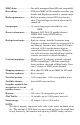
Table of Contents Sec. 1: Read Me First! ............................................................... 1 Capabilities and Specifications: GlobalMap 3300C ...................... 2 How Lowrance GPS Works .......................................................... 4 Introduction to GPS and WAAS................................................... 6 Free Training Aids Available ....................................................... 8 Unit Emulator ................................................................
Set Man Overboard (MOB) Waypoint........................................ 48 Navigate Back to MOB Waypoint .............................................. 48 Navigate to Cursor Position on Map.......................................... 49 Navigate to a Point of Interest................................................... 50 Creating and Saving a Trail....................................................... 50 Displaying a Saved Trail ............................................................
Selecting a Waypoint .............................................................. 72 Set a Waypoint by Average Position ...................................... 72 Set a Waypoint by Projecting a Position................................ 72 Sec. 5: System & GPS Setup Options................................... 73 Alarms ......................................................................................... 73 Check MMC Files and Storage Space ........................................
Track Smoothing......................................................................... 97 Trail Options ............................................................................... 98 Delete All Trails ...................................................................... 98 Update Trail Option................................................................ 98 Update Trail Criteria (Auto, Time, Distance).................... 98 Trail Update Rate (Time, Distance) ...................................
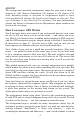
Section 1: Read Me First! How this manual can get you out on the road, fast! Welcome to the exciting world of digital GPS! We know you're anxious to begin navigating, but we have a favor to ask. Before you grab the GlobalMap 3300C and begin installing it, please give us a moment or two to explain how our manual can help you get the best performance from your compact, color display, mapping GPS receiver. First, we want to thank you for buying a Lowrance GPS unit.
After you've learned the basics (or if you already have some GPS experience), you may want to try out some of the GlobalMap 3300C's many advanced navigation features. That brings us to Section 4, Advanced GPS Operations. This section contains the rest of the unit's GPS command functions, organized in alphabetical order.
MMC slots:...........................One with waterproof door (SD card compatible). Recording:........................ GPS uses MMC & SD cards for recording trip details and displaying charts or custom maps. Back-up memory: .......... Built-in memory stores GPS data for decades. User settings are stored when unit is turned off. Languages:...................... 10; menu languages selectable by user. GPS Receiver/antenna:............
NOTICE! The storage and operation temperature range for your unit is from -4 degrees to +167 degrees Fahrenheit (-20 degrees to +75 degrees Celsius). Extended storage or operation in temperatures higher or lower than specified will damage the liquid crystal display in your unit. This type of damage is not covered by the warranty. For more information, contact the factory's Customer Service Department; phone numbers are listed on the last page.
MapCreate map. There is so much detail in our background map (and even more in MapCreate) that we'll describe their contents and differences in Section 3, Basic GPS Operations, on page 27. Another portion of the unit's onboard memory is devoted to recording GPS navigation information, which includes waypoints, event marker icons, trails and routes. This lets you look back the way you came. Think of this data storage like the hard drive memory in a computer or a tape in a cassette tape recorder.
The unit automatically reads Custom Map Files directly from the MMC or SD card. To use a custom map, all you need to do is slide an MMC containing a map into the unit. Introduction to GPS and WAAS Well, now you know the basics of how the unit does its work. You might be ready to jump ahead to Section 2, Installation & Accessories, on page 11, so you can mount your unit and plug in the power. Or you might want to see how our text formatting makes the manual tutorials easy to skim.
The system requires signal reception from three satellites in order to determine a position. This is called a 2D fix. It takes four satellites to determine both position and elevation (your height above sea level — also called altitude.) This is called a 3D fix. Remember, the unit must have a clear view of the satellites in order to receive their signals. Unlike radio or television signals, GPS works at very high frequencies.
Also remember that this unit will always show navigation information in the shortest line from your present position to a waypoint, regardless of terrain! It only calculates position, it can’t know what’s between you and your destination, for example. It’s up to you to safely navigate around obstacles, no matter how you’re using this product.
The emulator works exactly like your real GPS unit. Using the GPS Simulator feature, it allows you to run GPS routes and trails, even create real waypoints you can use in the field! And that's just some of the material available on our web site. To find out all we have available, go to WWW.LOWRANCE.COM and look around. For now, though, we'll get back to how to use this particular unit. And, first, how to use the manual.
2. Press ↓ to Trail 1|ENT|→ to NAVIGATE|ENT. 3. You are asked to wait while it converts the trail into a route. 4. The wait message disappears and the unit begins showing navigation information along the trail. Now, begin moving and follow your unit's directions. Translated into complete English, step 1 above would mean: "Start on the Map Page. Press the Menu key twice. Next, repeatedly press (or press and hold) the down arrow key to scroll down the menu and select (highlight) the My Trails menu command.
Section 2: Installation & Accessories Preparations You can install the GPS system in some other order if you prefer, but we recommend this installation sequence: Caution: You should read over this entire installation section before drilling any holes in your vehicle or vessel! 1. Determine the approximate location for the GPS unit, so you can plan how and where to route the cables for the antenna and power. This will help you make sure you have enough cable length for the desired configuration. 2.
LGC-2000 Module, bottom view (left) and top view (right). GPS Module Installation The GPS module can be mounted on any flat surface, provided there is access behind the mounting surface for the screws. The optional magnet allows the module to be easily used on cars or off-road vehicles. The pole mount adapter lets you mount the antenna on a pole or swivel mount that uses standard marine 1" - 14 threads.
If you need to route the cable through the mounting surface, drill a 1" (25mm) hole for the cable's connector. There is a notch in the antenna housing that allows the cable to pass through to the outside, if desired, instead of routing it through the mounting surface. After drilling the holes, pass the O-ring over the cable and press it into the groove on the bottom of the antenna housing. Now attach the antenna to the mounting surface, using 4 mm screws and the supplied lock washers.
Drill size 3/16" (4.75 mm) Drill four places. Drill size 1" (25 mm ) (If needed.) GPS module mounting template. After the module is installed, connect it to the unit. The LGC-2000 can communicate with your GPS unit either directly (using the supplied extension cable) or through a NMEA 2000 network. Connecting Directly to the Unit After the module is installed, attach it to the end of the Y-adapter extension cable as shown in the following diagram.
NOTE: The extension cable’s shorter branch will have a 60-ohm terminator attached to it. Do not remove this terminator. When you're not connecting to a NMEA 2000 buss, you must leave the terminator connected to this socket for your antenna/receiver to function correctly. Connecting to a NMEA 2000 Network The LGC-2000 can be connected to a NMEA 2000 buss, providing GPS information to any Lowrance GPS units attached to the buss.
NOTE: An existing operational NMEA 2000 buss will already have terminators in place and will already be powered. If you're connecting to such a network, you won't need the terminators provided. Do not add terminators or power to a functional NMEA 2000 buss! When the LGC-2000 is connected to the unit (directly or indirectly), it will begin providing GPS signal information.
Powering a NMEA 2000 Buss (NMEA 2000 Power cable) A NMEA 2000 buss must be connected to a power source to operate. If you have a pre-existing NMEA 2000 installation, it may already be connected to another power source. If your NMEA 2000 buss is already powered, you can ignore the NMEA 2000 Power cable. Never attach two power sources to a single NMEA 2000 buss.
power cable when the unit is not in use. When you are not using the unit, you should always shut off power to the power cable, especially when the power cable is disconnected from the unit. If possible, keep the power cable away from other boat wiring, especially the engine's wires. This will provide the best isolation from electrical noise. If the cable is not long enough, splice #18 gauge wire onto it. The power cable has two wires, red and black. Red is the positive lead, black is negative or ground.
If a malfunction happens inside the unit, extensive damage can occur if the enclosed fuse is not used. As with all electrical devices, this unit could be damaged to a point that it is unrepairable and could even cause harm to the user when not properly fused. CAUTION: Do not use this product without a 3-amp fuse wired into the power cable! Failure to use a 3-amp fuse will void your warranty. This unit has reverse polarity protection. No damage will occur if the power wires are reversed.
NMEA 0183 Cable Connections NMEA is a standard communications format for marine electronic equipment. For example, an autopilot can connect to the NMEA interface on this unit and receive positioning information. The unit can exchange information with any device that transmits or receives NMEA 0183 data. See the following diagram for general wiring connections. Read your other product’s owner’s manual for more wiring information.
GPS unit, rear view Network socket Power/Data socket NMEA 0183 Data cable (four wires) LGC-2000 25' extension cable NMEA 2000 Power cable 60-ohm terminator Power Supply cable GPS antenna module Cable connections shown. Mounting the Unit: Bracket or In-Dash Installation You can install the unit on the top of a dash with the supplied gimbal bracket. It can also be installed in the dash or mounted on a portable power supply.
Optional R-A-M mounting system. Bracket Installation Mount the unit in any convenient location, provided there is clearance behind the unit when it's tilted for the best viewing angle. You should also make sure there is enough room behind the unit to attach the power, transducer and GPS antenna/receiver module cables. (A drawing on the next page shows the dimensions of a gimbal-mounted unit.) Holes in the bracket's base allow wood screw or through-bolt mounting.
Drill a 1-inch (25.4 mm) hole in the dash for the power, transducer and antenna cables. The best location for this hole is immediately under the gimbal bracket location. This way, the bracket can be installed so that it covers the hole, holds the cables in position and results in a neat installation. Some customers, however, prefer to mount the bracket to the side of the cable hole — it's a matter of personal preference. 77.1 [3.03] 27.6 [1.09] 173.9 [6.85] 137.9 [5.43] 157.9 [6.22] 56.9 [2.
place against the side of the hole. Finally, fasten the bracket to the dash. Attach the unit to the gimbal bracket using the supplied gimbal knobs and washers. In-Dash Installation You can mount the unit in the dash with an optional FM-5 In-Dash Adapter Kit. The kit includes mounting hardware, a template for cutting the hole and an instruction sheet, part 988-0147-43. 146.5 [5.76] Top R 7.9 [0.31] In-Dash Template 113.5 [4.
Additional MMC cards are available from LEI Extras; see ordering information inside the back cover of this manual. MMCs and SD cards are also available at many camera and consumer electronics stores. The MMC slot is located in a compartment on the front of the case. The compartment door is located at the lower right corner. The following figure shows a close-up with the door opened. Thumb screw Insert card face up, this way Memory card compartment with a 16 MB MMC card installed. To remove an MMC 1.
Other Accessories Other accessories include MMC cards, MMC card readers and MapCreate™ 6 custom mapping software for your computer. MMC card readers are available in USB and parallel port versions. MapCreate™ 6 CD-ROM, left; MMC card reader for USB ports, right. WARNING: When the unit is mounted in an unprotected area, such as an open boat cockpit, the protective face cover must be removed when the vehicle is moving at high speed. This includes towing a boat on a trailer at highway speeds.
Section 3: Basic GPS Operations This section addresses the unit's most basic GPS operations. The tutorials presented in Sec. 3 follow a chronological order. Sec. 4, Advanced GPS Operations, will discuss other more advanced functions and utilities. Material in Sec. 4 is arranged in alphabetical order. Before you turn on the unit and find where you are, it's a good idea to learn about the different keys, the three Page screens and how they all work together.
3. MENU – Press this key to show the menus and submenus, which allow you to select a command or adjust a feature. This also accesses search functions for streets, intersections, addresses and highway exits. 4. ARROW KEYS – These keys are used to navigate through the menus, make menu selections and move the map cursor. 5. ENT/ICONS (Enter & Icons) – This key allows you to save data, accept values or execute menu commands. It is also used to create event marker icons. 6.
Main Menu. The Main Menu commands and their functions are: Screen command: changes the contrast or brightness of the display screen. Sounds command: enables or disables the sounds for key strokes and alarms and sets the alarm style. Transparency command: adjust the level of transparency for menus. Alarms command: turns GPS alarms on or off and changes alarm thresholds. Route Planning command: used to plan, view or navigate a route. My Trails command: shows, hides, creates and deletes plot trails.
Trip Calculator command: shows trip status and statistics. Timers command: controls the up timer, down timer and alarm clock settings. Browse MMC Files command: this allows you to view the installed MMC card and the files it contains. Pages The unit has three Page displays that represent the three major operating modes. They are the Satellite Status Page, the Navigation Page and Map Page. They are accessed by pressing the PAGES key, then using → or ← to select a Page.
WARNING: Do not begin navigating with this unit until the numbers have stopped flashing! Satellite Status Page. Left view indicates unit has not locked on to any satellites and does not have a fix on its position. Center view shows satellites being scanned. Right view shows satellite lock-on with a 3D position acquired (latitude, longitude and altitude), and WAAS reception. This screen shows a graphical view of the satellites that are in view.
This also gives you an indicator of the fix quality the unit currently has. The smaller the position error number, the better (and more accurate) the fix is. If the position error flashes dashes, then the unit hasn't locked onto the satellites, and the number shown isn't valid. (For details, see the Customize Page Displays entry in Sec. 5.) The Satellite Status Page has its own menu, which is used for setting various options. (Options and setup are discussed in Sec. 5).
NOTE: Remember, when the Speed, Track and Position information displays are flashing, satellite lock has not been achieved and no position fix has been determined. A question mark will also flash on the present position arrow in the center of the compass rose. Speed (ground speed) is the velocity you are making over the ground. (If you wish, you can customize the Speed data box to display Closing Speed instead. Closing Speed is also known as velocity made good.
The cross track error range is shown on the compass rose as a wide, white, corridor enclosing the course line. The outer edges of this white corridor represent lines that show the current cross track error range. The default for the cross track error range is 0.20 miles. For example, if the present position symbol touches the right cross track error line, then you are 0.20 miles to the right of the desired course. You need to steer left to return to the desired course.
The arrow in the center of the screen is your present position. It points in the direction you're traveling. The solid line extending from the back of the arrow is your plot trail, or path you've taken. The map zoom range is the distance across the screen. This number shows in the lower left corner of the screen. In the first of the following example figures, the range is 4,000 miles from the left edge of the map to the right edge of the map.
Map Pages with high-detail MapCreate map of an urban area loaded on the MMC. At left, arterial streets are visible at the 4 mile zoom range. Center, numerous dots representing Points of Interest are visible at the 2 mile range, along with minor streets. Right, at the 0.4 mile zoom, you can see an interstate highway with an exit, major and minor streets as well as Point of Interest icons. Background map vs.
NOTE: Available through LEI Extras (look inside back cover for accessory ordering information), FreedomMaps are pre-made maps that contain all of the same information available in a custom MapCreate map, without any of the work of preparation. Minor Streets Interstate Major Street Cursor line POI Marker POI Pop-up School POI Restaurant POI Position, distance and bearing data Zoom Range When the map is zoomed out far enough, most POIs appear as square dots.
The Pages Menu also offers several map display options under the Map Page category. To access them, press PAGES|← or → to MAP|↓ to Option|EXIT. Digital Data map page option. In pages that have two major windows (such as two maps) you can toggle back and forth between the two windows by pressing PAGES|PAGES. This allows you to change which map your cursor moves on, and which map the menu operates on. Pages Menu with Two Map option selected, left. Map Page with two map windows, at right.
1. From any two-window display, press MENU|↓ to RESIZE WINDOW|ENT. 2. Four flashing arrows appear along the centerline dividing the two windows. Press an arrow key perpendicular to the centerline to adjust the window widths. Press an arrow key parallel to the centerline to switch between horizontal and vertical layout. Press EXIT to clear the four flashing arrows. Fig. 1. Fig. 3. Fig. 2. Fig. 4. From left to right: Fig. 1. Resize Window command on the GPS Page menu. Fig. 2.
Basic GPS Quick Reference Start outdoors, with a clear view of the open sky. As you practice, try navigating to a location at least a few blocks away. While you're learning, navigation in too small an area will constantly trigger arrival alarms. 1. Connect the unit to electric power and the antenna module. Make sure the MMC is in. (See complete installation details beginning on page 11.) 2. To turn on the unit, press and release PWR key. 3.
Find Your Current Position Finding your current position is as simple as turning the unit on. Under clear sky conditions, the unit automatically searches for satellites and calculates its position in approximately one minute or less. NOTE: "Clear sky" means open sky, unobstructed by terrain, dense foliage or structures. Clouds do not restrict GPS signal reception. If for some reason satellite acquisition takes longer, you may be inside a structure or vehicle or in terrain that is blocking signal reception.
Distance measured by cursor Pop-up name box Selected wreck Cursor line Cursor line The selected wreck (the Empress) to the southeast is 12.81 miles away. Selecting Any Map Item With the Cursor 1. Use the zoom keys and the arrow keys to move around the map and find the item you wish to select. 2. Use the arrow keys and center the cursor cross-hair on the desired object. On most items, a pop-up box will give the name of the selected item.
NOTE: This example requires the Point of Interest (POI) database included with a high detail MapCreate 6 custom map. After the unit has acquired a position: 1. Press WPT|↓ to POI-RESTAURANTS. 2. You could search the entire restaurant category, but in this example we will narrow our search. Press → to FAST FOOD CHAINS|ENT|↓ to NEAREST|ENT. 3. The unit says it is calculating, then a list of restaurants appears, with the closest at the top of the list, and the farthest at the bottom of the list.
POI information screen on fast food restaurant nearest this position. Screen shows name, street address, phone number, latitude/longitude, distance to restaurant and its compass bearing. Figure at left shows Go To waypoint command; right figure shows Find On Map command. 6. The unit's map appears, with the cross-hair cursor highlighting the restaurant' s POI symbol. A pop-up data box shows the POI's name.
NOTE: Search works from mapping and POI data loaded in the unit. If you do not have a high-detailed custom map (containing POI data) for the area you are searching loaded on the MMC, you may not find anything. Set a Waypoint A waypoint is simply an electronic "address," based on the latitude and longitude of a position on the earth. A waypoint represents a location, spot, or destination that can be stored in memory, then be recalled and used later on for navigation purposes.
Step 1. Step 2. Step 3. Step 4. Sequence for setting a waypoint. Step 1: while traveling, quickly press WPT twice to call up Find Waypoint screen (seen in Step 2) and set a point. Step 3: a message says the waypoint has been saved. Step 4: vehicle continues on its way; number waypoint symbol is visible on map. Create Waypoint on Map 1. Use the arrow keys to move the cursor to the place where you want to make a waypoint. 2. Press WPT|WPT.
4. Press ↓ to LONGITUDE|ENT. Enter the longitude by pressing ↑ or ↓ to change the first character, then press → to the next character and repeat until the longitude is correct. Press ENT, then EXIT|EXIT to return to the previous page display. The waypoint is saved and automatically given a name with a sequential number, such as "waypoint 001." The waypoint symbol and number appear on the map and in the waypoint list.
Set Man Overboard (MOB) Waypoint One of boating's most terrifying events is having a friend or family member fall overboard. This situation can be deadly on any body of water — fresh or salt. It's particularly dangerous at night or if you're out of sight of land. Of course, the first thing to do is remain calm and then use all standard safety procedures to rescue the person. This unit has a man overboard feature that shows navigation data to the location where the feature was activated.
The man overboard position is also stored in the waypoint list for future reference. It can be edited the same as any other waypoint. This prevents the inadvertent loss of the current Man Overboard position. To cancel navigation to MOB, press MENU|MENU|↓ to CANCEL NAVIGAto YES|ENT. The unit stops showing navigation information. TION|ENT|← Navigate to Cursor Position on Map The GO TO CURSOR command: navigates to the current cursor position on the map.
The 30-mile zoom figure at left clearly shows the red course line connecting your current position to your destination. The 30-mile zoom, center, shows both current position and direction to destination on screen. The Navigation Page, right, will also show navigation information. To stop navigating to the cursor, use the Cancel Navigation command: press MENU|MENU|↓ to CANCEL NAVIGATION|ENT|← to YES|ENT. The unit stops showing navigation information.
The unit is set at the factory to automatically create and record a trail while the unit is turned on. The unit will continue recording the trail until the length reaches the maximum trail point setting (default is 2,000, but the unit can record trails 9,999 points long). When the point limit is reached, the unit begins recording the trail over itself. With the default auto setting, this unit creates a trail by placing a dot (trail point) on the screen every time you change directions.
New trail, named "Trail 4," is created when Trail 3 is made inactive. Any new travel will be recorded in this trail, which is active and visible. Trails do not need to be visible in order to be active. You can save and recall up to 10 different plot trails, which can also be copied to your MMC for archiving or for transfer to your MapCreate software. Tip: Another quick way to stop recording one trail and begin a new one is to use the New Trail command: Press MENU|MENU|↓ to MY TRAILS|ENT|ENT.
To turn on trail display: 1. Press MENU|MENU|↓ to MY TRAILS|ENT. 2. Press ↓|↓|↓ to enter the Saved Trail list, then use ↑ or ↓ to select the desired Trail Name|ENT. 3. Press ↓ to VISIBLE|ENT. To return to the previous page, press EXIT|EXIT|EXIT|EXIT. Navigating Trails There are three methods for following a trail: visual trailing, navigating a trail (forward) and backtracking a trail (backward). Try each method to see which you prefer. Visual trailing is the simplest method.
NOTE: If you are already located at or near the beginning of your trail, the arrival alarm will go off as soon as you hit Enter. Just press EXIT to clear the alarm and proceed. 5. Now, begin moving and follow your unit. 6. When you reach your destination, be sure to cancel your navigation: press MENU|MENU|↓ to CANCEL NAVIGATION|ENT. The unit asks if you're sure; press ←|ENT. Figure 1. Figure 3. Figure 2. Figure 4. Navigate a trail menu sequence: Fig. 1, My Trails command. Fig. 2, Trails Menu. Fig.
much turn off the visible trail option. The Navigation Page will show only the red course line, unless you are recording a new trail. The bearing arrow on the compass rose points to the next waypoint on the trail. As you travel, the arrival alarm will go off when you near a trail waypoint, and the bearing arrow on the compass rose will swing around and point to the next trail waypoint. Press EXIT to clear the alarm.
Navigate a Back Trail (backtrack, or reverse) 1. Press MENU|MENU|↓ to MY TRAILS|ENT. 2. Press ↓|↓|↓ to enter the Saved Trail list, then use ↑ or ↓ to select the desired Trail Name|ENT. 3. Press ↓ to DELETE TRAIL|→ to NAVIGATE|ENT. 4. Press → to REVERSE ROUTE|ENT|← to NAVIGATE ROUTE|ENT. The unit begins showing navigation information along the trail, in reverse. NOTE: If you are already located at or near the end of your trail, the arrival alarm will go off as soon as you hit Enter.
The Transfer My Data submenu asks if you want to save data to the MMC or load data from the MMC into the unit's memory. 2. The Transfer My Data menu includes a message which tells you if an MMC is present or not. If no MMC is present, you must first insert a card into the unit in order to activate the Load or Save commands. To transfer data from the unit to the MMC: press ENT (for SAVE.) To transfer data from the MMC to the unit: press → to LOAD|ENT. 3.
4. Loading to unit memory: There may be more than one GPS Data File (*.USR) on the card. To select a file, press ENT to activate the selection box, use ↓ or ↑ to highlight the file, then press ENT to accept the selection. Next, press ↓ to LOAD DATA|ENT. The unit will display a completion message when the data transfer is finished. To return to the Page view, press EXIT|EXIT|EXIT|EXIT. Figure 1. Figure 2. Figure 3. Figure 4.
Section 4: Advanced GPS Operations Find Distance From Current Position To Another Location 1. While on the Map Page press: MENU|↓ to FIND DISTANCE|ENT. 2. Center your cursor over the position you want to find the distance to. A rubber band line appears, connecting your current position to the cursor's location. The distance along that line will appear in a pop-up box. The box also shows the bearing to the point you're measuring to. 3. Press EXIT|EXIT to return to regular operation.
Icons Icons are graphic symbols used to mark some location, personal point of interest or event. They can be placed on the map screen, saved and recalled later for navigation purposes. These are sometimes referred to as event marker icons. This unit has 42 different symbols you can pick from when creating an icon. Icons are similar to waypoints, but they do not store as much information (like names) as waypoints do. You can't use a menu to navigate to icons as you can with waypoints.
Delete an Icon You can delete all the icons at one time, you can delete all icons represented by a particular symbol, or you can use the cursor to delete a selected icon from the map. 1. Press MENU|↓ to DELETE MY ICONS|ENT. 2. Press ↓ to DELETE ALL ICONS, DELETE BY SYMBOL, or DELETE FROM MAP and press ENT. Delete icons menu. The Delete All Icons command will ask if you are sure. Press ← to YES|ENT. All icons will be deleted from the map. The Delete by Symbol command will launch the Select Symbol menu.
Routes A route is a series of waypoints, linked together in an ordered sequence, that's used to mark a course of travel. You can visualize a route as a string of beads: The beads represent waypoints and the string represents the course of travel connecting waypoint to waypoint. The course from one waypoint to the next is a leg; routes are composed of one or more legs. The legs of all GPS routes are based on straight lines between waypoints.
Route Planning command on Main Menu, left, will open the Route List screen, right. 2. If necessary, press ↑ to select NEW ROUTE, then press ENT. (To add to an existing route, press ↓ or ↑ to route name|ENT.) 3. Press ↓ to (ROUTE END)|ENT|↓ to ADD FROM MAP|ENT. The Map Page appears with the cursor showing. Edit Route menu, left. Edit Route Waypoints menu, right, with Add From Map command selected. 4.
1. 2. 3. 1. 2. 3. Route creation sequence, from left: Fig. 1. Set route waypoint (1) at the cove entrance. Fig. 2. Move cursor northeast to set point (2) at channel entrance. Fig. 3. With point (2) set, move cursor southeast to mark channel exit with waypoint (3). In figures 2 and 3, notice the rubber band line extending from the previously set waypoint to the cursor. This line will become the course for the route. 4. 5. 6. Route creation sequence, continued: Fig. 4. Point (3) set at channel mouth.
8. To save your route, press EXIT. The unit reverts to the Edit Route screen, with the route automatically named "Route 1" and stored in the unit's internal memory. You can edit the route and run other commands, but if you are finished with the route for now, return to the last page displayed by pressing EXIT|EXIT|EXIT. NOTE: When adding waypoints to an existing route, the inserted waypoints will appear in the route in front of the waypoint you have selected in the Edit Route menu.
1. From the NAVIGATION PAGE, press MENU|ENT or from the MAP PAGE press MENU|MENU|↓ to ROUTE PLANNING|ENT. 2. Press ↓ to route name|ENT|↓ to Route Waypoints List. Use ↓ and ↑ to select a waypoint, then press ENT. Edit Route Waypoints menu. 3. Use ↓ and ↑ to select a command from the Edit Route Waypoints menu and press ENT. Add From Map lets you insert a waypoint in the route by clicking on a map location with the cursor. Add Waypoint calls up the Waypoint List so you can insert a waypoint from the list.
Route Planning command on Main Menu, left; Routes menu, center; Edit Route menu, right. Navigate Route command is selected. 2. Press ↓ to select route name|ENT|ENT. 3. Upon arrival at your destination, cancel navigation: press MENU|MENU|↓ to CANCEL NAVIGATION|ENT|← to YES|ENT. The following figures show what the Navigation Page and Map Page look like while navigating a route. Navigate a Route in Reverse Here's how you run a route backward, from the end waypoint to the beginning waypoint: 1.
Figure 2. Figure 1. Navigating along a route: Fig. 1 shows the Navigation Page at the start of a route, heading straight for the first waypoint (Wpt 1). In Fig. 2, the traveler has arrived at Wpt 1; the arrival alarm has been triggered and the bearing arrow on the compass rose has turned to point toward Wpt 2, off to the northeast. Figure 4. Figure 3. In Fig. 3 the traveler has turned northeast on his new course and is heading straight for Wpt 2, which is 0.27 miles away. Fig.
Tip: You can also delete all trails at once: 1. Press MENU|MENU|↓ to MY TRAILS|ENT. 2. Press → to DELETE ALL|ENT|← to YES|ENT. Edit a Trail Name To edit a trail name: press MENU|MENU|↓ to MY TRAILS|ENT|↓ to trail name|ENT|ENT. Press ↑ or ↓ to change the first character, then press → to the next character and repeat until the name is correct. Press ENT then EXIT|EXIT|EXIT|EXIT to return to the previous page display.
At left, Edit Trail Menu with Pattern option selected. At right, edited trail with dotted line pattern. Utilities Utilities are useful tools for traveling or for outdoor activities. Alarm Clock To get to the alarm clock menu: press MENU|MENU|↓ to TIMERS|ENT|↓ to ALARM CLOCK|ENT. Sun/Moon Rise & Set Calculator To get to the Sun/Moon menu: press MENU|MENU|↓ to SUN/MOON CALCULATIONS|ENT. Trip Calculator To get to the Calculator menu: press MENU|MENU|↓ to TRIP CALCULATOR|ENT.
To delete a waypoint from the map: 1. Use the arrow keys to select the waypoint with the cursor. 2. Press WPT|→ to DELETE WAYPOINT|ENT|← to YES|ENT. To return to the previous page and clear the cursor, press EXIT. To delete all waypoints at one time: press MENU|MENU|↓ to SYSTEM SETUP|ENT|↓ to DELETE ALL MY WAYPOINTS|ENT|← to YES|ENT. To return to the previous page, press EXIT|EXIT. Edit a Waypoint Waypoint Name To edit waypoint name: 1.
Selecting a Waypoint To select a waypoint on the map (for navigating to, for editing, etc.,) use the arrow keys and center the cursor over the waypoint. A highlighted halo will appear around the waypoint. Set a Waypoint by Average Position This feature sets a waypoint at the current position after taking several position readings and averaging them. This boosts waypoint position accuracy by helping to eliminate errors caused by atmospheric conditions and other factors. 1.
Section 5: System & GPS Setup Options Alarms This unit has several GPS alarms. The factory default setting has all of these but the anchor alarm turned on. You can turn the alarms off and on and change their distance settings. You can set an arrival alarm to flash a warning message and sound a tone when you cross a preset distance from a waypoint. For example, if you have the arrival alarm set to .1 mile, then the alarm will flash a message when you come within .1 mile of the recalled waypoint.
3. To change distance settings, scroll ↓ or ↑ to select the desired category, then press → |ENT to activate the distance dialog box. Press ↑ or ↓ to change the first character, then press → to the next character and repeat until the name is correct. 4. When your adjustments are finished, return to the last page displayed by repeatedly pressing EXIT. IMPORTANT ALARM NOTES: Anchor Alarm - The anchor alarm may be triggered even when you're sitting still. This typically happens when using small (less than .
Menus for changing Com Port settings. For connectors and wiring information for another device, see page 20. For assistance in configuring the unit to communicate with another device, consult the factory; customer service phone numbers are in the back of this manual. Also see the entry below for Configure NMEA. To set Com Port Configuration: 1. Press MENU|MENU|↓ to SYSTEM SETUP|ENT. 2. Press ↓ to COMMUNICATIONS PORT|ENT. Configure NMEA You can configure the unit to use specific NMEA sentences. 1.
• GGA transmits time, position, and fix related data. • GSA and GSV transmits fix mode, DOP values, and satellites in view information. • DBT transmits the depth below the transducer. • DPT transmits the depth • MTW transmits the water temperature. • VLW transmits the distance traveled through water as measured by the paddle wheel. • VHW transmits the water speed as measured by the paddle wheel. 4.
(Universal Transverse Mercator) projection; MGRS (Standard); MGRS (Standard + 10); Map Fix; Loran TD; British, Irish, Finnish, German, New Zealand, Swedish, Swiss, Taiwan and Greek grid systems. UTM's are marked on USGS topographic charts. This system divides the Earth into 60 zones, each 6 degrees wide in longitude. British, Irish, Finnish, German, New Zealand, Swedish, Swiss, Taiwan, and Greek grid systems are the national coordinate system used only in their respective countries.
Map Fix Map Fix is used with charts or maps. This system asks for a reference position in latitude/longitude, which you take from a marked location on the map. It then shows the present position as distance on the map from that reference point. For example, if it shows a distance of UP 4.00" and LEFT 0.50", you then measure up three inches and to the left a half-inch from the reference point on the map to find your location.
Press → to SELECT ORIGIN|ENT|ENT|ENT to bring up the waypoint list. Select the waypoint (or a landmark of POI) that you saved the reference point under and press ENT. The unit displays a waypoint information screen with the command SET AS ORIGIN selected; press ENT and the unit returns to the Configure Map Fix menu. Finally, press EXIT to erase this menu. Now press ↑ to COORD SYSTEM|ENT, select MAP FIX from the list and press ENT|EXIT.
GPS Setup Menu, left; GPS Simulator menu, center. Map Page showing Track and Speed steering arrow indicators, right. In this example, you are "traveling" across Mudisland Point on a track of 19º at a speed of 50 miles per hour. Make the desired settings, then turn the simulator on by highlighting the GPS SIMULATOR ON box and pressing ENT key. Press EXIT|EXIT|EXIT to erase this menu. A message and tone appear periodically, warning you that the simulator is on.
tion begins. Press EXIT to clear the alarm.) When navigation starts, press ↑ to increase speed to the desired setting. 4. Press EXIT to turn off the steering and speed boxes. The unit will now automatically "steer" along the trail or route. When you arrive at your "destination," cancel navigation as you normally do. Tip: You can pick any spot on the map to begin your simulation session by using the Initialize GPS command. This makes your unit think it's located at the position you select.
Map Data This menu lets you turn the map off, if desired (which turns the map screen into a GPS plotter); turn off or on the pop-up map info boxes; draw the map boundaries or boxes around the areas of high detail; or fill land areas with gray. You can also turn on or off Map Overlays, which display latitude and longitude grid lines or range rings on the map. This menu lets you select Navionics Maps; for instructions, see the Navionics Charts entry in this section.
Fill Water With White From the Map Page, press MENU|↓ to MAP DATA|ENT. Press ↓ to FILL WATER WITH WHITE. With the option highlighted, press ENT to check it (turn on) and uncheck it (turn off.) After the option is set, press EXIT|EXIT to return to the page display. Map Overlays (Range Rings; Lat/Long Grid) The map screen can be customized with four range rings and/or grids that divide the plotter into equal segments of latitude and longitude.
3. To return to the last page displayed, press EXIT|EXIT. A list of the datums used by this unit is in the back of this manual. GPS Setup Menu, left, Map Datum Menu, right. Map Detail Category Selection This menu determines which of the mapping features are shown on the screen. This includes, waypoints, trails, icons, cities, highways, etc. You can selectively turn on or off any of these items, customizing the map to your needs. To get to Map Categories: 1.
Map Orientation By default, this receiver shows the map with north always at the top of the screen. This is the way most maps and charts are printed on paper. In Track Up mode, map shows "N" and arrow to indicate north. Map orientation at left is shown in north up and at right, track up. This is fine if you're always traveling due north. What you see to your left corresponds to the left side of the map, to your right is shown on the right side of the map, and so on.
Map Menu, left; Map Orientation menu with the North Up map orientation option selected, right. NOTE: In North Up and Course Up, the present position arrow appears in the center of the map page. In Track Up, the position arrow appears centered in the lower third of the page. Navionics Charts Your unit can display Navionics electronic charts on MMCs. They work just like a MapCreate custom map on an MMC. To display a Navionics chart: 1.
These figures show menu sequence (from left to right) for selecting a Navionics chart for the South Chesapeake Bay area. 3. To turn off a Navionics chart, From the Map Page, press MENU|↓ to MAP DATA|ENT|↓ to NAVIONICS MAP CHOICE|ENT. Use ↑ or ↓ to select LOWRANCE, then press ENT|EXIT|EXIT. Port Information Navionics charts contain Port Services information, represented by anchor icons on the map display. An example is displayed in the following figure. To view Port Services information: 1.
3. To scroll through the Service Categories window: press ENT then use ↑ or ↓ to see the types of services available. As you highlight a different category, the list in the lower window changes. To return to the Map Page, press EXIT|EXIT. 4. Depending on the location, the Detailed Services window may have a long list of services under the General Services category.
Tidal Current Station icon in animated mode Pop-up name box Cursor lines Navionics chart showing Tidal Current Station icon selected by cursor. In this example, the current is flowing to the west at 0.2 kn. 2. Press WPT to display the Tidal Current Information screen. Current Information screen. The Tidal Current Information screen displays daily tidal current data for this station on this date at the present time.
1. Use → and ← to highlight month, day or year, then press ENT. 2. Use ↑ and ↓ to select the desired month, day or year, then press ENT. To clear the information screen, press EXIT. Tide Information Navionics charts contain Tidal Information, represented at large zoom ranges by a box icon with the letter "T." The icon stands for a Tidal Station location. An example is displayed at right.
Tide Information screen. The Tide Information screen displays daily tidal data for this station on this date at the present time. The graph at the top of the screen is an approximate view of the tidal range pattern for the day, from midnight (MN), to noon (NN) to midnight (MN). The dotted line across the graph is the Mean Lower Low Water line (MLLW). The height scale on the top right side of the graph changes, based upon the maximum range of the tide for that day.
System Setup Menu, left, with Pop-up Help command highlighted. At right, this example shows the Pop-up Help message for the Overlay Data command, located on the Map Page menu. Position Pinning When you are standing still or moving at extremely slow speed, a GPS receiver can have trouble determining the direction you are traveling. In the past, this resulted in a "wandering" plot trail that moved around the map, even if you were standing still.
System Menu with Reset Options command selected. Require WAAS You can force the unit to require WAAS for reporting a valid position. (The default setting, off, uses WAAS automatically, but doesn't require it to yield a position.) Here's how to turn it on and off: 1. Press MENU|MENU|↓ to GPS SETUP|ENT|↓ to REQUIRE WAAS|ENT. 2. To return to the last page displayed, press EXIT|EXIT. 3. You can return to this command and press ENT again to turn the feature off. Require WAAS command on the GPS Setup Menu.
Once in the Screen menu: To adjust the display's contrast: The CONTRAST slider bar is already selected. Press → or ← to move the bar. The left end of the scale is minimum contrast; the right end is maximum contrast. Screen Command, left, and Screen Menu with Contrast bar selected, right. To adjust the display's brightness: Press ↓ to BRIGHTNESS. Press → or ← to move the bar. The left end of the scale is minimum contrast; the right end is maximum contrast.
Set Language This unit's menus are available in 10 languages: English, French, German, Spanish, Italian, Danish, Swedish, Russian, Dutch and Finnish. To select a different language: 1. Press MENU|MENU|↓ to SYSTEM SETUP|ENT. 2. Press ↓ to SET LANGUAGE…|ENT. 3. Use ↓ or ↑ to select a different language and press ENT. All menus now appear in the language you selected. Set Local Time Using the correct local time setting is handy when estimating local arrival time while navigating.
That can result in the alarm repeatedly going on and off. If you want, you have the option of turning off the WAAS Acquired/Lost alarm without affecting how the unit uses WAAS. Here's how: 1. Press MENU|MENU|↓ to GPS SETUP|ENT|↓ to SHOW WAAS ALARM. 2. With the option highlighted, press ENT to uncheck it (turn off) and check it (turn on.) After the option is set, press EXIT|EXIT to return to the page display. 3. You can return to this command and press ENT again to turn the feature on.
Sounds command, left. At right, the Sounds menu. Once in the Sounds menu: To set Key Press Sounds: With the option highlighted, press ENT to check it (turn on) and uncheck it (turn off.) After the option is set, press EXIT|EXIT to return to the page display. To set Alarm Sounds: Press ↓ to ALARM SOUNDS. With the option highlighted, press ENT to check it (turn on) and uncheck it (turn off.) After the option is set, press EXIT|EXIT to return to the page display. To set Alarm Volume: Press ↓ to VOLUME.
Trail Options There are several options you can use with trails. Some affect all trails, other options can be applied to a particular trail. You can change the way trails are updated, display or hide trails, create a new trail, delete a trail, etc. General Trail Options To access the Trails Menu: 1. Press MENU|MENU|↓ to MY TRAILS|ENT. Main Menu, left, Trails Menu, center, Trail Options, right.
unit "drops" a plot point (trail waypoint) onto the trail. This conserves plot trail points. If a plot trail uses all of the available points allotted to it, the beginning points are taken away and placed at the end of the trail. From the Trails Menu, press ↓ to OPTIONS|ENT|↓ to UPDATE CRITERIA. Press ← or → to select criteria type|ENT. Trail Update Rate (Time, Distance) You can update a trail by time, with a range from 1 second to 9999 seconds; the default is 3 seconds.
Edit Trail menu. New Trail To manually start a new trail, in the Trails Menu, make sure NEW TRAIL is highlighted and press ENT. Trail Visible/Invisible and Other Trail Options The name, maximum number of points in the trail, activity, and visibility are all changed on the Edit Trail menu screen. The Active setting determines whether or not the unit is recording new points for a particular trail. On the Edit Trail menu, press ↓ or ↑ to highlight the section you wish to change, then press ENT.
Main Menu with Transparency command selected. To adjust Menu Transparency level: Press MENU|MENU|↓ to TRANSPARENCY|ENT. The TRANSPARENCY slider bar appears. Press ↑ or ↓ to move the bar. The lower end of the scale makes the menus opaque; the upper end is maximum transparency. Units of Measure This menu sets the speed and distance (statute or nautical miles, meters), depth (feet, fathoms, or meters), temperature (degrees Fahrenheit or Celsius) and heading (true or magnetic) units.
Notes 102
Section 6: Searching NOTE: The background map loaded in your unit lets you to search for U.S. Interstate Highway exits and exit services, as well as some land features, including cities and lakes. For a full set of searchable land features, including landmarks, streets, addresses and Points of Interest, you must load your own high-detail custom map produced with our MapCreate 6 software. For a complete description of what detail is found in the background map and custom MapCreate maps, see page 36.
In search results, the distance and bearing to the selected item will be calculated from the current position. In the case of a cursor search, the search results show distance and bearing from the cursor, but an individual waypoint's information screen shows distance and bearing from the current (or last known) position. Find Addresses 1. From the Map Page, press MENU|↓ to FIND ADDRESS|ENT. 2. Press ENT to search in the Address field. 3.
Find Address menu, left; Find Street menu, center, with Find By Name field active; street name entry complete, right. 5. To enter a city name, press ↓ to CITY|ENT. You will be asked if you want to find addresses only within a particular city. This option is designed so you can limit an address search to a single city if necessary (see the following note). If you select yes, there are two options: A. You can spell out the city name in the top selection box.
6. When the necessary search fields are filled in, press ↓ to FIND ADYour unit asks you to wait while it searches for the address. (If an address is not in the database, a message appears saying the address could not be found.) DRESS|ENT. 7. The unit will display a list of addresses. If the address you are looking for is highlighted at the top of the list, press ENT. If not, use ↓ and ↑ to select the correct address from the list, then press ENT.
Left, Map Page showing location of the address on the map, highlighted by cursor. Center, this address is a business in the POI database, so you can display the POI information window, then navigate to it. At right, this address is not in the POI database, so the Waypoint key will not display any information for this address. Find Any Item Selected by Map Cursor On the Map Page: with a POI or map feature selected by the cursor press WPT. To return to the previous page, press EXIT.
Find Highway Exits command, left, and Find Exit menu, right. 2. First, select a highway name by pressing ENT, which calls up the Find By Name menu. There are two highway search options: A. You can spell out the highway name in the top selection box. Press ↑ or ↓ to change the first letter, then press → to move the cursor to the next letter and repeat until the name is correct, then press ENT|ENT. B.
Find Exit menu, with an exit selected in the Exit List. 4. In the Exit Information screen you have two choices. A. Press ENT to navigate or "go to" the exit. B. Press →|ENT to find the exit on the map. "Go To Exit" option, left, "Find On Map" option, right. Tip: You can also look up some additional information on the Exit Services located near this exit. Press ↓ to SERVICES|press ↓ or ↑ to select Service Name|ENT.
Exit Information screen, left; general location and amenities information, at right. Find Map Places or Points of Interest (POI) 1. Press WPT, press ↓ or ↑ to select a map place or POI category, then press ENT. (To narrow your search, press → or ← to select a subcategory before pressing ENT.) You will be given two options; Search By Name or By Nearest. Find Waypoint menu with Lodging POI category selected, left, and with the RV Parks subcategory selected, right. 2. Search by nearest POI. Press ↓|ENT.
Find by Nearest option, left, Calculating screen, center, POI list, right. 3. Search by name of POI. Press ENT. There are two options: A. You can spell out the POI in the top selection box. Press ↑ or ↓ to change the first letter, then press → to move the cursor to the next letter and repeat until the name is correct, then press ENT|ENT. B. Jump down to the lower selection list by pressing ENT, then press ↓ or ↑ to select a POI from the list, then press ENT to call up the POI's Waypoint Information screen.
"Go To" POI option, left, "Find on Map" POI option, right. Find Streets or Intersections Find a Street 1. From the Map Page, press MENU|↓ to FIND STREETS|ENT and the Find Streets Menu appears. Find Streets command, left, Find Streets menu, right. 2. You must first fill in a street name in the First Street dialog box. Press ENT to display the Find By Name menu. There are two options: A. You can spell out the street in the top selection box.
Find Street By Name menu. Spell out name in the top box, or select from the list in the lower box. 3. The Find Streets menu reappears with the street you're searching for in the First Street box. (In this example, it's I-35.) To search for that street, press ↓ to FIND FIRST STREET|ENT. A message appears asking you to wait while the unit finds the street. When the Streets Found list appears, press ↑ or ↓ to select the street you are searching for and press ENT.
Map Page showing results of a street search. The cursor points to the located street. If you want to navigate to the found street at the cursor location, just press MENU|ENT|EXIT. Find an Intersection You must enter one street in the First Street dialog box and enter the next street in the Second Street dialog box. 1. From the Map Page, press MENU|↓ to FIND STREETS|ENT and the Find Streets Menu appears. 2. You must fill in a street name in the First Street dialog box.
5. The Find Streets menu reappears with the first and second street dialog boxes filled in. In this example, we selected I-44 as our second street. You could now use similar techniques to select a city or Zip code, but your search will probably be faster if you leave those boxes blank. (You can specify a city and/or Zip code later on to narrow the search, if the resulting list is too long.) Find Intersection command highlighted, left. Intersections Found list, right. 6.
If you want to navigate to the found intersection, just press MENU|ENT|EXIT. Find Waypoints 1. Press WPT|↑ to MY WAYPOINTS|ENT. 2. If searching for the waypoint By Name, press ENT. If searching for the Nearest waypoint, press ↓ to NEAREST|ENT. (To search by name, jump to step 5.) Find Waypoint menu, left; Find By Nearest command, center, Find by Name command, right. 3. If you're looking for nearest, the unit says it is calculating, then a list of waypoints appears.
4. To see location information on the closest (highlighted) waypoint, press ENT and the Waypoint Information screen appears. (If you wanted to, you could select another waypoint from the list with the ↑ or ↓ keys.) A. To navigate to the waypoint, press ENT. (The Go To Waypoint command is already highlighted.) The unit will show navigation information to the waypoint. B. To find the waypoint, press → to FIND ON MAP|ENT. The Map Page appears with the cursor highlighting the found waypoint.
Find By Name menu, left. Waypoint Information screen, center. At right, the found waypoint is highlighted by the cursor on the Map Page. A. To navigate to the waypoint, press ENT. (Go To Waypoint command is already highlighted.) The unit will show navigation information to the waypoint. B. To find the waypoint, press → to FIND ON MAP|ENT. The Map Page appears with the cursor highlighting the found waypoint.
Section 7: Supplemental Material Datums Used by This Unit WGS 1984 Default Zaire, Zambia and Zimbabwe Adindan Mean for Ethiopia, Sudan Arc 1950 - Botswana Adindan Burkina Faso Arc 1950 - Lesotho Arc 1950 - Burundi Arc 1950 - Malawi Adindan Cameroon Adindan Ethiopia Arc 1950 - Swaziland Adindan Mali Arc 1950 - Zimbabwe Adindan Senegal Arc 1960 - Mean for Kenya, Tanzania Adindan Sudan Ascension Island 1958 - Ascension Island Ain el Abd 1970 Bahrain Ain el Abd 1970 Saudi Arabia Anna 1 Astro 1965
Chua Astro Paraguay Corrego Alegre Brazil Dabola Guinea Djakarta (Batavia) Indonesia (Sumatra) DOS 1968 New Georgia Islands (Gizo Island) Easter Island 1967 Easter Island European 1950 Mean for Austria, Belgium, Denmark, Finland, France, West Germany, Gibraltar, Greece, Italy, Luxembourg, Netherlands, Norway, Portugal, Spain, Sweden, Switzerland European 1950 Mean for Austria, Denmark, France, West Germany, Netherlands, Switzerland European 1950 Mean for Iraq, Israel, Jordan, Lebanon, Kuwait, Saudi Arabia,
Naparima BWI Trinidad & Tobago North American 1927 Mean for Antigua, Barbados, Barbuda, Caicos Islands, Cuba, Dominican Republic, Grand Cayman, Jamaica, Turks Islands North American 1927 Mean for Belize, Costa Rica, El Salvador, Guatemala, Honduras, Nicaragua North American 1927 Mean for Canada North American 1927 Mean for CONUS (Continental United States) North American 1927 Mean for CONUS (East of Mississippi River) including Louisiana, Missouri, Minnesota North American 1927 Mean for CONUS (West of Missi
South American 1969 Chile Tokyo Mean for Japan, Korea, Okinawa South American 1969 Colombia Tokyo Japan South American 1969 Ecuador Tokyo Korea South American 1969 Ecuador (Baltra, Galapagos) Tokyo South American 1969 Guyana Tristan Astro 1968 Tristan da Cunha South American 1969 Paraguay South American 1969 Peru Viti Levu 1916 Fiji (Viti Levu Island) South American 1969 Trinidad & Tobago Eniwetok 1960 Point 58 Sweden Santo (DOS) 1965 Espirito Santo Island Sao Braz Azores (Sao Miguel, Santa Ma
FCC Compliance This device complies with Part 15 of the U.S. Federal Communications Commission (FCC) Rules. Operation is subject to the following two conditions: (1) this device may not cause harmful interference, and (2) this device must accept any interference received, including interference that may cause undesired operation. Changes or modifications not expressly approved by the manufacturer could void the user's authority to operate the equipment.
Notes 124
Index A G Accessories, 1, 3, 4, 5, 6, 11, 21, 22, 26, 37, 56, 103 Sec.
57, 58, 62, 74, 86 Reset Options, 39, 45, 92, 93 Route, 3, 5, 7, 9, 10, 11, 13, 29, 32, 40, 54, 56, 62, 63, 64, 65, 66, 67, 68, 74, 80, 81, 92 Create and Save, 62 Delete, 65 Navigate, 66, 67 N Navigating, 10, 40, 47, 48, 49, 50, 53, 54, 55, 56, 61, 66, 67, 74 A Route, 66, 67 A Trail, 53 Cancel, 29, 40, 49, 50, 54, 56, 58, 67 To Cursor Position, 49 To Icon, 61 Nearest, 42, 43, 44, 47, 103, 110, 111, 116 NMEA, 3, 11, 14, 15, 16, 17, 18, 19, 20, 74, 75 S Searching, 2, 8, 41, 42, 43, 44, 46, 47, 48, 50, 59,
Utilities, 27, 30, 70 106, 107, 110, 111, 116, 117, 118 Delete, 70 Edit, 71 Search, 116 Select, 72 W WAAS, 3, 4, 6, 7, 11, 31, 93, 95, 96 Require WAAS, 93 Waypoints, 2, 3, 5, 8, 9, 24, 28, 29, 32, 33, 34, 40, 42, 43, 44, 45, 46, 47, 48, 49, 50, 55, 56, 60, 62, 63, 64, 65, 66, 67, 68, 70, 71, 72, 73, 74, 77, 78, 79, 80, 81, 84, 85, 92, 95, 99, 103, 104, Z Zooming, 3, 28, 34, 35, 40, 41, 53, 63, 81 Auto Zoom, 81 127
Notes 128
LOWRANCE DATABASES LICENSE AGREEMENT THIS IS A LEGAL AGREEMENT BETWEEN THE END-USER WHO FIRST PURCHASES THIS PRODUCT AS A CONSUMER ITEM FOR PERSONAL, FAMILY, OR HOUSEHOLD USE ("YOU") AND LOWRANCE ELECTRONICS, INC., THE MANUFACTURER OF THIS PRODUCT ("WE", "OUR", OR "US"). USING THE PRODUCT ACCOMPANIED BY THIS LICENSE AGREEMENT CONSTITUTES ACCEPTANCE OF THESE TERMS AND CONDITIONS. IF YOU DO NOT ACCEPT ALL TERMS AND CONDITIONS, PROMPTLY RETURN THE PRODUCT WITHIN 30 DAYS OF PURCHASE.
DATABASES LIMITED WARRANTY "We", "our", or "us" refers to Lowrance Electronics, Inc., the manufacturer of this product. "You" or "your" refers to the first person who purchases the product as a consumer item for personal, family, or household use. The Databases Limited Warranty applies to the one or more databases that your product may contain. We refer to each of these as a "Database" or together as the "Databases.
LOWRANCE ELECTRONICS FULL ONE-YEAR WARRANTY "We," "our," or "us" refers to LOWRANCE ELECTRONICS, INC., the manufacturer of this product. "You" or "your" refers to the first person who purchases this product as a consumer item for personal, family or household use. We warrant this product against defects or malfunctions in materials and workmanship, and against failure to conform to this product's written specifications, all for one (1) year from the date of original purchase by you.
How to Obtain Service… …in the USA: We back your investment in quality products with quick, expert service and genuine Lowrance parts. If you're in the United States and you have technical, return or repair questions, please contact the Factory Customer Service Department. Before any product can be returned, you must call customer service to determine if a return is necessary. Many times, customer service can resolve your problem over the phone without sending your product to the factory.
Accessory Ordering Information for all countries To order Lowrance accessories such as power or adapter cables, please contact: 1) Your local marine dealer or consumer electronics store. Most quality dealers that handle marine electronic equipment or other consumer electronics should be able to assist you with these items. To locate a Lowrance dealer near you, visit our web site, www.lowrance.com and look for the Dealer Locator. Or, you can consult your telephone directory for listings. 2) U.S.
Visit our web site: Lowrance Pub. 988-0156-021 Printed in USA 020604 © Copyright 2004 All Rights Reserved Lowrance Electronics, Inc.