Pub. 988-0151-041 www.lowrance.
Copyright © 2002 Lowrance Electronics, Inc. All rights reserved. Lowrance® is a registered trademark of Lowrance Electronics, Inc. MapCreate is a trademark of Lowrance Electronics, Inc. Marine-Tex is a trademark of Illinois Tool Works Inc. Navionics is a registered trademark of Navionics, Inc. Points of Interest Data in this unit are by infoUSA, copyright 2001-2002, All Rights Reserved. infoUSA is a trademark of infoUSA, Inc. eXitSource Database, copyright 2001-2002 Zenrin Co. Ltd.
Table of Contents Sec. 1: Read Me First! ............................................................... 1 Capabilities and Specifications: GlobalMap 7000C................... 2 How Lowrance GPS Works .......................................................... 4 Introduction to GPS and WAAS................................................... 6 How to Use this Manual: Typographical Conventions................ 8 Sec. 2: Installation & Accessories ........................................
Displaying a Saved Trail ............................................................ 45 Navigating Trails........................................................................ 45 Visual Trailing ........................................................................ 46 Navigate a Trail (Forward)..................................................... 46 Navigate a Back Trail (Backtrack, or Reverse) ..................... 48 Transfer Custom Maps and GPS Data Files .............................
Configure DGPS.......................................................................... 68 Configure NMEA ........................................................................ 68 Coordinate System Selection...................................................... 69 To Setup Loran Td: ................................................................. 70 Map Fix ....................................................................................... 70 Customize Page Displays .................................
Delete All Trails ...................................................................... 92 Update Trail Option................................................................ 92 Delete Trail ............................................................................. 93 New Trail................................................................................. 93 Trail Visible/Invisible and Other Trail Options .................... 93 Units of Measure.........................................................
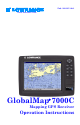
Section 1: Read Me First! How this manual can get you out on the road, fast! Welcome to the exciting world of GPS satellite navigation! We know you're anxious to begin finding your way with this space-age technology, but we have a favor to ask. Before you grab the GlobalMap 7000C and begin installing it, please give us a moment or two to explain how our manual can help you get the best performance from your highresolution, high-performance GPS+WAAS chart recorder.
Section 3 contains short, easy-to-scan GPS lessons that follow one another in chronological order. They're all you'll need to know to find your way on the water or in the wilderness quickly. After you've learned the basics (or if you already have some GPS experience), you may want to try out some of the GlobalMap 7000C's many advanced navigation features. That brings us to Section 4, Advanced GPS Operations. This section contains the rest of the unit's GPS command functions, organized in alphabetical order.
Input power:................... 10 to 15 volts DC. Current drain: ............... 450 ma with lights off; 1 amp with lights on. Case size:......................... (With bracket) 9.1" H x 12.2" W x 4" D (23.1 x 31 x 10.2 cm); sealed and waterproof; suitable for saltwater use. MMC slots: ...................... Two in waterproof compartments (SD card compatible). Back-up memory: .......... Built-in memory stores GPS data for decades. User settings are stored when unit is turned off. Languages:................
Graphic symbols for waypoints or event marker icons: ................. 42. Routes:............................. 100; up to 100 waypoints per route. Plot Trails: ...................... 10 savable; up to 9,999 points per trail. Zoom range:.................... 37 ranges; 0.05 to 4,000 miles. NOTE: The above memory capacities refer only to the GlobalMap 7000C's on-board memory. The amount of GPS data you can record and save for recall later is only limited by the number of MMC cards you have.
relation to those satellites. Once the GlobalMap 7000C figures its latitude and longitude, it plots that position on the moving map shown on the screen. The whole process takes place several times a second! The performance doesn't stop there. Stored in the permanent memory of each unit is a basic background map of the entire world. We lock it in here at the factory — you can't change or erase this map.
tail than the basic background map. These Custom Map Files (file format *.lcm) can also be shared between Lowrance GPS or sonar/GPS units and personal computers. This unit automatically reads Custom Map Files directly from the MMC or SDC. To use a custom map, all you need to do is slide an MMC containing a map into the GlobalMap 7000C. Introduction to GPS and WAAS Well, now you know the basics of how the unit does its work.
A minimum of three satellites are required to determine a 2D fix. Remember, the unit must have a clear view of the satellites in order to receive their signals. Unlike radio or television signals, GPS works at very high frequencies. These signals can be easily blocked by trees, buildings, an automobile roof, even your body. Like most GPS receivers, this unit doesn’t have a compass or any other navigation aid built inside. It relies solely on the signals from the satellites to calculate a position.
First, the U.S. government has not completed construction of the WAAS system, so it is not yet fully operational. The ground stations are in place, but only a few of the needed WAAS satellites have been launched. WAAS can boost the accuracy of land GPS navigation, but the system is designed for aircraft. The satellites are in a fixed orbit around the Equator, so they appear very low in the sky to someone on the ground in North America.
Menu Commands A menu command or a menu option will appear in small capital letters, in a bold sans serif type like this: ROUTE PLANNING. These indicate that you are to select this command or option from a menu or take an action of some kind with the menu item. Text that you may need to enter or file names you need to select are show in italic type, such as trail name.
Notes 10
Section 2: Installation & Accessories Preparations You can install the GPS system in some other order if you prefer, but we recommend this installation sequence: Caution: You should read over this entire installation section before drilling any holes in your vehicle or vessel! 1. Determine the approximate location for the GPS unit, so you can plan how and where to route the cables for the antenna and power. This will help you make sure you have enough cable length for the desired configuration. 2.
You need to select an antenna installation location that has a clear, unobstructed view of the sky. After the module is installed, route the cable to the unit, plug it in the center socket on the back and your system is ready to use. See the module's instruction sheet, publication part number 988-0147-39, for complete installation directions. In an automobile, you may achieve good results by simply placing the external antenna on the top of the dash, at the base of the windshield.
CAUTION: Do not use this product without a 6-amp fuse wired into the power cable! Failure to use a 6-amp fuse will void your warranty. This unit has reverse polarity protection. No damage will occur if the power wires are reversed. However, the unit will not work until the wires are attached correctly. An optional 8-foot, CA-4 external power cable with a cigarette lighter adapter is available from Lowrance.
Communication Port Wiring Diagrams Com-1 To unit Yellow (Transmit) Receive Orange (Receive) Transmit Shield (Ground) Ground To DGPS Receiver Com-1 wiring to receive DGPS position information from a DGPS receiver. Com-1 To unit Orange (Receive) NMEA Transmit Shield (Ground) Ground To Other GPS Receiver Com-1 wiring to receive NMEA position information from some other GPS receiver.
12.2 [310.3] 3.6 [91.8] 9.1 [231.3] Inch [Millimeter] 2.3 [58] Front view (left) and side view (right) showing dimensions of the GPS unit when mounted on gimbal bracket. Cable hole Screw mounting hole Front Install the gimbal bracket. Orient the bracket so the arms slope toward the front of your unit.
Holes in the bracket's base allow wood screw or through-bolt mounting. You may need to place a piece of plywood on the back side of thin fiberglass panels to reinforce the panel and secure the mounting hardware. Once a location is determined, use the bracket as a template and mark the mounting holes and the hole for the cables. Drill a 1-inch (25.4 mm) hole in the dash for the power and antenna cables. Screw the bracket to the mounting surface.
MMC groove for card removal Thumb screw Insert card face up, this way Memory card compartment with a 16 MB MMC card installed. To remove an MMC 1. Open the card compartment door by unscrewing the thumb screw. The screw should only be finger tight. If it was over-tightened, use a thumbnail, a coin or a screwdriver to open the door. 2. Use a thumbnail or fingernail to grab the groove in the bottom of the MMC. See the figure above for the groove location. 3. Drag the MMC from the slot.
its anti-glare properties, always use the special cleaner available from your dealer or LEI Extras. To remove fingerprints, water spots, dust or other grime from the screen, hold the bottle about 6 inches (15 cm) from the screen and spray. Wipe immediately with a clean, dry, lint-free cloth. MMC and MapCreate Other available accessories include MMC cards, MMC card readers and MapCreate™ 6 custom mapping software for your computer. MMC card readers are available in USB and parallel port versions.
Next, connect the speaker to your unit. The external audio wires are the labeled red and black wires in the power/data cable. The speaker's input cable should have two exposed wires: a positive and a negative (ground). Connect the speaker's positive wire to the unit's red speaker wire, and the speaker's negative (ground) wire to the unit's black speaker wire. The unit should automatically begin to play any active sounds through the attached speaker.
Notes 20
Section 3: Basic GPS Operations This section addresses the unit's most basic GPS operations. The tutorials presented in Sec. 3 follow a chronological order. Sec. 4, Advanced GPS Operations, will discuss other more advanced functions and utilities. Material in Sec. 4 is arranged in alphabetical order. Before you turn on the GlobalMap 7000C and find where you are, it's a good idea to learn about the different keys, the three Page screens and how they all work together.
3. MENU – Press this key to show the menus and submenus, which allow you to select a command or adjust a feature. This also accesses search functions for streets, intersections, addresses and highway exits. 4. ARROW KEYS – These keys are used to navigate through the menus, make menu selections, move the map cursor and enter data. 5. ENT/ICONS (Enter & Icons) – This key allows you to save data, accept values or execute menu commands. It is also used to create event marker icons. 6.
Main Menu. The Main Menu commands and their functions are: Screen command: changes the contrast or brightness of the display screen. Sounds command: enables or disables the sounds for key strokes and alarms and sets the alarm style. Alarms command: turns GPS alarms on or off and changes alarm thresholds. Route Planning command: used to plan, view or navigate a route. My Trails command: shows, hides, creates and deletes plot trails. Also used to navigate or backtrack a trail.
Pages The unit has three Page displays that represent the three major operating modes. They are the Satellite Status Page, the Navigation Page and the Map Page. They are accessed by pressing the PAGES key, then using → or ← to select a Page. (Clear the Pages Menu by pressing EXIT.) Pages Menu, showing some Map display options. Satellite Status Page The Satellite Status Page, shown, provides detailed information on the status of the GlobalMap 7000C's satellite lock-on and position acquisition.
Satellite Status Page. Left view indicates unit has not locked on to any satellites and does not have a fix on its position. Right view shows satellite lock-on with a 3D position acquired (latitude, longitude and altitude), and WAAS reception. This screen shows a graphical view of the satellites that are in view. Each satellite is shown on the circular chart relative to your position. The point in the center of the chart is directly overhead.
Navigation Page This screen has a compass rose that not only shows your direction of travel, but also the direction to a recalled waypoint. To get to the Navigation Page: Press PAGES| → or ← to NAVIGATION|EXIT. The navigation screen looks like the one below when you're not navigating to a waypoint or following a route or trail. Your position is shown by an arrow in the center of the screen. Your trail history, or path you've just taken, is depicted by the line extending from the arrow.
Speed instead. Closing Speed is also known as velocity made good. It's the speed that you're making toward the waypoint. For instructions, see the Customize Page Displays entry in Sec. 5.) Track is the heading, or the current direction you are actually traveling. Bearing is the direction of a line-of-sight from your present position to the destination. No matter what direction you are steering, the Bearing window shows the compass direction straight to the destination from your location at the moment.
Current track or heading, shown in degrees Course line Bearing arrow Compass bearing to destination Waypoint symbol Navigation information displays Cross track error range (off course indicator) Left cross track error line Trail line Destination name Navigation Page, backtracking a trail while creating a new trail. In the example figure above, the driver is headed north (a 355º track) toward a waypoint 355º (bearing) away. The cross track error range (white corridor) is 0.
The map zoom range is the distance across the screen. This number shows in the lower right corner of the screen. In the first example figure below, the range is 4,000 miles from the left edge of the map to the right edge of the map. The Zoom In and Zoom Out keys zoom the map to enlarge or reduce its coverage area and the amount of mapping detail shown. There are 37 available map zoom ranges, from 0.05 miles to 4,000 miles. Far left, Map Page opening screen.
The medium-detail U.S. maps contain: all incorporated cities; shaded metropolitan areas; county boundaries; shaded public lands (such as national forests and parks); some major city streets; Interstate, U.S. and state highways; Interstate highway exits and exit services information; large- and medium-sized lakes and streams; and more than 60,000 navigation aids and 10,000 wrecks and obstructions in U.S.
can reduce screen clutter and make streets and other map features easier to see by simply turning off the display of POIs you're not watching for. (To see how, check the text on Map Detail Category Selection, page 77. It shows how to use the Map Categories Drawn menu to turn individual POI displays off and on.) Even though their display is turned off, you can still search for POIs and their icons will pop-up when your unit finds them for you.
Resize Window is another extremely handy feature for pages that have two major windows. You can change the horizontal size of the windows to suit your viewing preference. Here's how: 1. From any two-window display, press MENU|↓ to RESIZE WINDOW|ENT. 2. Two flashing arrows appear along the centerline dividing the two windows. Press ← or → to adjust the window widths. Press EXIT to clear the menu. 3. To change the window size again or revert back to the original display, just follow the steps above.
GPS Quick Reference Start outdoors, with a clear view of the open sky. As you practice, try navigating to a location at least a few blocks away. While you're learning, navigation in too small an area will constantly trigger arrival alarms. 1. Connect the unit to electric power and the antenna module. Make sure the MMC is in. (See complete installation details beginning on page 11.) 2. To turn on the GlobalMap 7000C, press and release PWR key. 3.
Find Your Current Position Finding your current position is as simple as turning the GlobalMap 7000C on. Under clear sky conditions, the unit automatically searches for satellites and calculates its position in approximately one minute or less. NOTE: "Clear sky" means open sky, unobstructed by terrain, dense foliage or structures. Clouds do not restrict GPS signal reception.
POI pop-up name box Cursor line Distance measured by cursor Selected airport Cursor line The selected airport to the northwest is 4.25 miles away. Selecting Any Map Item With the Cursor 1. Use the zoom keys and the arrow keys to move around the map and find the item you wish to select. 2. Use the arrow keys and center the cursor cross-hair on the desired object. On most items, a pop-up box will give the name of the selected item.
Category Selection menu, left, and list of the nearest restaurants, right. 4. If you wish, you could scroll ↑ or ↓ here to select another restaurant, but for now we will just accept the nearest one. Press ENT. 5. The POI information screen appears. (This is how you can use the GlobalMap 7000C as a business phone directory!) If you wanted to navigate there, you could press ENT, since the GO TO command is highlighted. But we just want to see it on the map, so press ↓ to FIND ON MAP|ENT.
Map screen showing Find Waypoint, the result of a restaurant search. 7. To clear the search and return to the last page displayed, press EXIT|EXIT|EXIT|EXIT. (Before you completely exited out of the Search menus, you could have gone looking for another place.) NOTE: Search works from mapping and POI data loaded in the GlobalMap 7000C. If you do not have a high-detailed custom map (containing POI data) for the area you are searching loaded on the MMC, you may not find anything.
Step 1. Step 2. Step 3. Step 4. Sequence for setting a waypoint. Step 1: while traveling, quickly press WPT twice to call up Find Waypoint screen (seen in Step 2) and set a point. Step 3: a message says the waypoint has been saved. Step 4: vehicle continues on its way; number waypoint symbol is visible on map. NOTE: The Quick Save method uses the default waypoint symbol until you edit an existing waypoint and change its symbol. (Edit Waypoint Symbol is described in Sec. 4.
Create Waypoint by Entering a Position 1. Press WPT|→ to SUBCATEGORY column|↓ to NEW|ENT. 2. Press ↓ to ENTERED POSITION|ENT|→ to CREATE|ENT. 3. Press → to LATITUDE|ENT. Enter the latitude by pressing ↑ or ↓ to change the first character, then press → to the next character and repeat until the latitude is correct. Press ENT. 4. Press ↓ to LONGITUDE|ENT. Enter the longitude by pressing ↑ or ↓ to change the first character, then press → to the next character and repeat until the longitude is correct.
Waypoint Course line (red) Trail line (magenta) Off course range, set at 0.20 mile Destination name Navigation Page, navigating toward waypoint 004 and leaving a trail. Set Man Overboard (MOB) Waypoint One of boating's most terrifying events is having a friend or family member fall overboard. This situation can be deadly on any body of water — fresh or salt. It's particularly dangerous at night or if you're out of sight of land.
Navigating to Man Overboard: Navigation Page, left, and Map Page, right. The victim is astern of the vessel; the GPS shows which direction to steer to for the rescue. The man overboard position is also stored in the waypoint list for future reference. It can be edited the same as any other waypoint. To cancel navigation to MOB, press MENU|MENU|↓ to CANCEL NAVIGATION|ENT|← to YES|ENT. The GlobalMap 7000C stops showing navigation information.
Navigate to cursor. In this example, the cursor has selected the town of Oologah, Oklahoma. 3. Press MENU|ENT and the GlobalMap 7000C will begin navigating to the cursor location. The Map Page will display a red line from your current position to the cursor position. The Navigation Page displays a compass rose showing navigation information to your destination. See the following examples.
lier in this section, or turn to Sec. 6, Searching, for detailed instructions on POI searches.) After you have looked up an item with the Find Waypoint command, use the → to make sure the GO TO command is highlighted at the top of the screen, then press ENT. The GlobalMap 7000C begins showing navigation information to the item. To cancel navigation, press MENU|MENU|↓ to CANCEL NAVIGATION|ENT|← to YES|ENT. The GlobalMap 7000C stops showing navigation information.
Visible symbol Active symbol Sequence for saving a trail and beginning a new one. At left, My Trails command. Center, the Trails Menu. The arrow to the right of Trail 17 indicates the trail is "active," and the check to the left indicates the trail is visible on the map display. The right figure shows the Edit Trail menu, with the Active command selected. 2. Press ↓ to the Active Trail Name|ENT. 3. Press ↓ to ACTIVE|ENT. This unchecks the Active option. 4.
Tip: Another quick way to stop recording one trail and begin a new one is to use the New Trail command: Press MENU|MENU|↓ to MY TRAILS|ENT|ENT. Caution: You also have the option of completely turning off trail recording, under the trail Options command. However, if the Update Active Trail option is left turned off, it will cancel the automatic trail creation feature. Displaying a Saved Trail The active trail is automatically displayed on the map (the "Visible" option) with the factory default settings.
The other two methods provide a full range of navigation data and work with both the Map Page and Navigation Page. The only difference between them is "navigating a trail" follows a trail forward (from start to end) while "backtracking" follows a trail in reverse (from end to start.) When hiking at walking speed with a hand-held GPS, we often just use visual back trailing because it is a bit better at following each little turn on a foot path.
Figure 1. Figure 2. Figure 3. Figure 4. Navigate a trail menu sequence: Fig. 1, My Trails command. Fig. 2, Trails Menu. Fig. 3, Edit Trail Menu. Fig. 4, Edit Route Menu with Navigate command highlighted for Trail 6. A trail is always converted to a "route" when you navigate the trail. On the Map Page, the trail you are navigating is represented by a magenta line. The Navigation Page will also show the navigated trail as a magenta line.
Present position arrow Trail point North Magenta trail line Navigate trail, map views: at left driver is northbound heading straight toward trail point 6. At right, northbound driver has reached point 6 and has turned west to follow trail.
NOTE: If you are already located at or near the end of your trail, the arrival alarm will go off as soon as you hit Enter. Just press EXIT to clear the alarm and proceed. 5. Now, begin moving and follow your GlobalMap 7000C. 6. When you reach your destination, be sure to cancel your navigation: press MENU|MENU|↓ to CANCEL NAVIGATION|ENT. The GlobalMap 7000C asks if you're sure; press ←|ENT. Transfer Custom Maps and GPS Data Files Custom Maps: Custom maps work only from the MMC card or SDC card.
The Transfer My Data submenu asks if you want to save data to the MMC or load data from the MMC into the GlobalMap 7000C's memory. 2. The Transfer My Data menu includes a message which tells you if an MMC is present or not. If no MMC is present, you must first insert a card into the GlobalMap 7000C in order to activate the Load or Save commands. To transfer data from the GlobalMap 7000C to the MMC: press ENT (for SAVE.) To transfer data from the MMC to the GlobalMap 7000C: press → to LOAD|ENT. 3.
From left to right, these figures show the menu sequence for naming and saving a GPS Data File from the GlobalMap 7000C's memory to an MMC. 4. Loading to unit memory: There may be more than one GPS Data File (*.USR) on the card. To select a file, press ENT to activate the selection box, use ↓ or ↑ to highlight the file, then press ENT to accept the selection. Next, press ↓ to LOAD|ENT. The unit will display a completion message when the data transfer is finished.
Cancel Navigation You can turn off any of the navigation commands after you reach your destination or at any other time by using the Cancel Navigation command. Press MENU|MENU|↓ to CANCEL NAVIGATION|ENT|← to YES|ENT.
Section 4: Advanced GPS Operations Find Distance From Current Position To Another Location 1. While on the Map Page press: MENU|↓ to FIND DISTANCE|ENT. 2. Center your cursor over the position you want to find the distance to. A rubber band line appears, connecting your current position to the cursor's location. The distance along that line will appear in a pop-up box. The box also shows the bearing to the point you're measuring to. 3. Press EXIT to return to regular operation.
called later for navigation purposes. These are sometimes referred to as event marker icons. The GlobalMap 7000C has 42 different symbols you can pick from when creating an icon. Icons are similar to waypoints, but they do not store as much information (like names) as waypoints do. You can't use a menu to navigate to icons as you can with waypoints. (But, you can use the map cursor and navigate to any icon on the map.
Delete icons menu. The Delete All Icons command will ask if you are sure. Press ← to YES|ENT. All icons will be deleted from the map. The Delete by Symbol command will launch the Select Symbol menu. Press ← or ↑ or → or ↓ to select the icon symbol to delete, then press ENT. A message appears saying all icons with the selected symbol have been deleted. The Delete From Map command will prompt you to move the cursor over an icon to select it. After selecting the icon, press ENT and it disappears from the map.
waypoint. Once programmed into the GPS unit, a route provides the option of navigating forward through the route waypoints or in reverse order (you can even begin navigating in the middle of a route!) Create and Save a Route You have the option of creating and editing a route in the unit, or you can make a route on your computer with our MapCreate 6 software.
Edit Route menu, left. Edit Route Waypoints menu, right, with Add From Map command selected. 3. Use the Zoom keys and arrow keys to move the map and cursor until the cursor is centered on the spot where you want your route to begin. (If you are starting at your current position or the current cursor position, you are already at the starting spot.) 4. Set the first route waypoint: press ENT. In this example, we moved to the intersection of 11th Street and 145th E. Ave.
5. Move the cursor to the next point in the route, a spot where you need to turn or change direction, and press ENT to set the next waypoint. 6. Repeat step five until the route reaches your destination. 7. To save your route, press EXIT. The GlobalMap 7000C reverts to the Edit Route screen, with the route automatically named "Route 1" and stored in the GlobalMap 7000C's internal memory. (In our example, Route 1 already existed, so the unit automatically made "Route 2.
Edit Route Waypoints menu. 3. Use ↓ and ↑ to select a command from the Edit Route Waypoints menu and press ENT. Add From Map lets you insert a waypoint in the route by clicking on a map location with the cursor. Add Waypoint calls up the Waypoint List so you can insert a waypoint from the list. Remove Waypoint will delete the waypoint from the route. View Waypoint will show you where the selected waypoint is on the map. Navigate a Route 1.
Navigate a Route in Reverse Here's how you run a route backward, from the end waypoint to the beginning waypoint: 1. From the NAVIGATION PAGE, press MENU|ENT or from the MAP PAGE, press MENU|MENU|↓ to ROUTE PLANNING|ENT. 2. Press ↓ to select route name|ENT|↓ to NAVIGATE|→ to REVERSE|ENT|← to NAVIGATE|ENT. 3. Upon arrival at your destination, cancel navigation: press MENU|MENU|↓ to CANCEL NAVIGATION|ENT|← to YES|ENT. Figure 1. Figure 2. Figure 3. Figure 4. Navigating along a route: Fig.
Trails Delete a Trail This is the command used to erase or delete a trail: Press MENU|MENU|↓ to MY TRAILS|ENT|↓ to trail name|ENT|→ to DELETE TRAIL|ENT|← to YES|ENT. Tip: You can also delete all trails at once: 1. Press MENU|MENU|↓ to MY TRAILS|ENT. 2. Press → to DELETE ALL|ENT|← to YES|ENT. Edit a Trail Name To edit a trail name: press MENU|MENU|↓ to MY TRAILS|ENT|↓ to trail name|ENT|ENT. Press ↑ or↓ to change the first character, then press → to the next character and repeat until the name is correct.
then press → to the next character and repeat until the pattern is correct. Press ENT, then EXIT|EXIT|EXIT|EXIT to return to the previous page display. At left, Edit Trail Menu with Pattern option selected. At right, edited trail with dotted line pattern. Utilities Utilities are useful tools for traveling or for outdoor activities. Alarm Clock To get to the alarm clock menu: press MENU|MENU|↓ to TIMERS|ENT|↓ to ALARM CLOCK|ENT.
To delete a waypoint from the map: 1. Use the arrow keys to select the waypoint with the cursor. 2. Press WPT|→ to DELETE WAYPOINT|ENT|← to YES|ENT. To return to the previous page and clear the cursor, press EXIT. To delete all waypoints at one time: press MENU|MENU|↓ to SYSTEM SETUP|ENT|↓ to DELETE ALL MY WAYPOINTS|ENT|← to YES|ENT. To return to the previous page, press EXIT|EXIT. Edit a Waypoint Waypoint Name To edit waypoint name: 1.
accuracy by helping to eliminate errors caused by atmospheric conditions and other factors. 1. Press WPT|→ to SUBCATEGORY column|↓ to NEW|ENT. 2. Press ↓ or ↑ to AVERAGE POSITION|ENT|press → to CREATE|ENT. 3. Wait while the unit takes points to average for the position. (The greater the number of points, the greater the accuracy.) When the desired number of points accumulates, press ENT to create and save the waypoint. 4. The Edit Waypoint menu appears.
Section 5: System & GPS Setup Options Alarms This unit has several GPS alarms. The factory default setting has all the alarms turned on. You can turn the alarms off and on and change their distance settings. You can set an arrival alarm to flash a warning message and sound a tone when you cross a preset distance from a waypoint. For example, if you have the arrival alarm set to 0.1 mile, then the alarm will flash a message when you come within 0.1 mile of the recalled waypoint.
4. When your adjustments are finished, return to the last page displayed by repeatedly pressing EXIT. IMPORTANT ALARM NOTES: Anchor Alarm - The anchor alarm may be triggered even when you're sitting still. This typically happens when using small (less than 0.05 mile) anchor alarm ranges.
GPS Auto Search on the Satellite Status Menu. You can force the unit to immediately kick into auto search mode. Here's how: 1. Press PAGES until you are on the Satellite Status screen. 2. Press MENU|↓ to GPS AUTO SEARCH|ENT|← to YES|ENT. Check MMC Files and Storage Space To check MMC Files: Press MENU|MENU|↓ to BROWSE MMC FILES|ENT. Main Menu, left, MMC File Browser, right. Communications Port Configuration The GlobalMap 7000C has two NMEA 0183 version 2.
Menus for changing Com Port settings. For assistance in configuring the unit to communicate with another device, consult the factory; customer service phone numbers are in the back of this manual. Also see the entries below for Configure DGPS and Configure NMEA. To set Com Port Configuration: 1. Press MENU|MENU|↓ to SYSTEM SETUP|ENT. 2. Press ↓ to COMMUNICATIONS PORT|ENT. Configure DGPS This unit will recognize Starlink, Magnavox and Lowrance DGPS receivers. 1. Press MENU|MENU|↓ to SYSTEM SETUP|ENT. 2.
1. Press MENU|MENU|↓ to SYSTEM SETUP|ENT. 2. Press ↓ to COMMUNICATIONS PORT|ENT|↓ to CONFIGURE NMEA|ENT. 3. A menu appears showing the prefixes of the available NMEA sentences. A check mark next to a prefix means the prefix is in use. Use ↑ ↓ → ← to select a prefix, then press ENT to turn off the prefix. (Press ENT again to check the box and turn a prefix on.) 4. When the desired prefixes are checked or unchecked, press EXIT|EXIT|EXIT|EXIT to return to the previous page.
datum for you when you select the grid. See the entry on Map Datum Selection for more information. The military grid reference system (MGRS) uses two grid lettering schemes, which are referred to as standard and standard + 10 MGRS on this unit. Your position and datum in use determines which one to use. If you use standard, and your position is off significantly, then try the alternate. NOTE: When the position format is changed, it affects the way all positions are shown on all screens.
For example, if it shows a distance of UP 4.00" and LEFT 0.50", you then measure up four inches and to the left a half-inch from the reference point on the map to find your location. To configure a map fix: To use this format, you need to follow these steps in order. First, take your map of the area and determine a reference latitude/longitude. (Please note that in order for this system to work, the latitude/longitude lines must be parallel with the edge of the map.
Press ↓ to SELECT ORIGIN WAYPOINT|ENT|ENT|ENT to bring up the waypoint list. Select the waypoint that you saved the reference point under and press ENT. The unit displays a waypoint information screen with the command SET AS ORIGIN selected; press ENT and the unit returns to the Configure Map Fix menu. Finally, press EXIT to erase this menu. Now press ↑ to COORD SYSTEM|ENT, select MAP FIX from the list and press ENT|EXIT. All position information now shows as a distance from the reference point you chose.
tion) or from a stored waypoint, map place or POI location (CHOOSE START command). You can steer your position and change speed on the map by using the arrow keys (STEER WITH ARROWS command) or by setting the track and speed in the dialog boxes provided on the simulator menu screen. To get to the GPS Simulator: 1. Press MENU|MENU|↓ to GPS SETUP|ENT. 2. Press ↓ to GPS SIMULATOR|ENT. The GPS Simulator Menu appears. GPS Setup Menu, left; GPS Simulator menu, right.
3. Begin navigating along the trail/route. (If you are close enough to the first waypoint, the arrival alarm will usually go off as soon as navigation begins. Press EXIT to clear the alarm.) When navigation starts, press ↑ to increase speed to the desired setting. 4. Press EXIT to turn off the steering and speed boxes. The unit will now automatically "steer" along the trail or route. When you arrive at your "destination," cancel navigation as you normally do.
Map Data This menu lets you turn the map off, if desired (which turns the map screen into a GPS plotter); turn off or on the pop-up map info boxes; draw the map boundaries or boxes around the areas of high detail; or fill water with white. You can also turn on or off Map Overlays, which display latitude and longitude grid lines or range rings on the map. This menu lets you select Navionics Maps; for instructions, see the Navionics Charts entry in this section.
Map Overlays (Range Rings; Lat/Long Grid) The map screen can be customized with four range rings and/or grids that divide the plotter into equal segments of latitude and longitude. Range rings are handy for visually estimating distances on the map. The ring diameters are based on the current zoom range. For example: at the 100 mile zoom, the screen will show two rings with your current position in the center.
GPS Setup Menu, left, Map Datum Menu, right. Map Detail Category Selection This menu determines which of the mapping features are shown on the screen. This includes, waypoints, trails, icons, cities, highways, etc. You can selectively turn on or off any of these items, customizing the map to your needs. To get to Map Categories: 1. From the Map Page, press MENU|↓ to MAP CATEGORIES DRAWN|ENT. 2. Press ↑ or ↓ to select a category or press → then press ↑ or ↓ to select a subcategory.
In Track Up mode, map shows "N" and arrow to indicate north. Map orientation at left is shown in north up and at right, track up. This is fine if you're always traveling due north. What you see to your left corresponds to the left side of the map, to your right is shown on the right side of the map, and so on. However, if you travel any other direction, the map doesn't line up with your view of the world. To correct this problem, a track-up mode rotates the map as you turn.
To select data for display: 1. From the Map page, press MENU|↓ to OVERLAY DATA|ENT. 2. Press ↓ or ↑ to select Data Type|ENT. Overlay Data command on the Map Menu, at left. Overlay Data Shown selection menu, right. In this example, we scrolled down the data list to highlight "Distance." Ground Speed and the Steering Arrow are already selected, as shown by the check marks beside their names. When selected, the data type shifts to the top of the data list and a check mark appears beside the data type.
2. Press ↓ or ↑ to select Data Type|press → or ← to select Data Size|ENT. The data will be shown in the new font size. To return to the previous page, press EXIT|EXIT. Speed Steering arrow Map Page showing boat cruising Keystone Lake with Overlay Data turned on. This example shows Ground Speed, Distance (to destination) and the Steering Arrow. Note that the Steering Arrow always points directly to the destination you are navigating toward.
WARNING: You should never format the MMC containing your Navionics chart. Formatting the MMC will permanently erase the chart from the card. 2. From the Map Page, press MENU|↓ to MAP DATA|ENT|↓ to MAP CHOICE|ENT. Use ↑ or ↓ to select the Map Name, then press ENT|EXIT|EXIT. These figures show menu sequence (from left to right) for selecting a Navionics chart for the South Chesapeake Bay area. 3. To turn off a Navionics chart, From the Map Page, press MENU|↓ to MAP DATA|ENT|↓ to MAP CHOICE|ENT.
Port Services icons Pop-up name box Cursor lines Navionics chart showing Port Services icon selected by cursor. 3. To scroll through the Service Categories window: press ENT then use ↑ or ↓ to see the types of services available. As you highlight a different category, the list in the lower window changes. To return to the Map Page, press EXIT|EXIT. 4. The General Services category includes a long list of items in the Detailed Services window.
you can select the boxed "C" icon and it becomes an animated arrow with a pop-up name box. An example is displayed in the following figure. To view Tidal Current information: 1. Use the arrow keys to move the cursor over a Tidal Current Station icon. When selected, a pop-up name box appears. 2. Press WPT to display the Tidal Current Information screen. Tidal Current Station icon in animated mode Pop-up name box Cursor lines Navionics chart showing Tidal Current Station icon selected by cursor.
Slack water, the period of little or no current, is represented by the Slack Water Line (SWL). The flood appears above the SWL and the ebb appears below the SWL. You can look up tidal current data for other dates by changing the month, day and year selection boxes. To select another date: 1. Use → and ← to highlight month, day or year, then press ENT. 2. Use ↑ and ↓ to select the desired month, day or year, then press ENT. To clear the information screen, press EXIT.
Tide Information screen. The Tide Information screen displays daily tidal data for this station on this date at the present time. The graph at the top of the screen is an approximate view of the tidal range pattern for the day, from midnight (MN), to noon (NN) to midnight (MN). The dotted line across the graph is the Mean Lower Low Water line (MLLW). The height scale on the top right side of the graph changes, based upon the maximum range of the tide for that day.
System Setup menu, left, with Pop-up Help command highlighted. At right, this example shows the Pop-up Help message for the Screen command, located on the Map Menu. Position Pinning When you are standing still or moving at extremely slow speed, a GPS receiver can have trouble determining the direction you are traveling. In the past, this resulted in a "wandering" plot trail that moved around the map, even if you were standing still.
Reset Options command, left, and the Reset Options Menu, right. Require DGPS You can force the GlobalMap 7000C to require DGPS for reporting a valid position. (The default setting, off, uses DGPS automatically when an optional DGPS beacon receiver is connected. However, this auto mode doesn't require DGPS reception to yield a position.) Here's how to turn mandatory DGPS on and off. 1. Press MENU|MENU|↓ to GPS SETUP|ENT|↓ to REQUIRE DGPS|ENT. 2. To return to the last page displayed, press EXIT|EXIT. 3.
Once in the Screen menu: To adjust the display's contrast: The CONTRAST slider bar is already selected. Press → or ← to move the bar. The left end of the scale is minimum contrast; the right end is maximum contrast. Screen Command, left, and Screen Menu with Contrast bar selected, right. To adjust the display's brightness: Press ↓ to BRIGHTNESS. Press → or ← to move the bar. The left end of the scale is minimum contrast; the right end is maximum contrast.
1. Press MENU|MENU|↓ to SYSTEM SETUP|ENT. 2. Press ↓ to SET LANGUAGE…|ENT. 3. Use ↓ or ↑ to select a different language and press ENT. All menus now appear in the language you selected. Set Local Time Using the correct local time setting is handy when estimating local arrival time while navigating. Also, the time and date are saved when a waypoint is created. To access the Set Local Time menu, you must first acquire your position.
2. With the option highlighted, press ENT to uncheck it (turn off) and check it (turn on). After the option is set, press EXIT|EXIT to return to the page display. 3. You can return to this command and press ENT again to turn the feature on. Software Version Information From time to time, Lowrance updates the operating system software in some of its products. These software upgrades are usually offered to customers as free downloads from our web site, www.lowrance.com.
Once in the Sounds menu: To set Key Press Sounds: With the option highlighted, press ENT to check it (turn on) and uncheck it (turn off). After the option is set, press EXIT|EXIT to return to the page display. To set Alarm Sounds: Press ↓ to ALARM SOUNDS. With the option highlighted, press ENT to check it (turn on) and uncheck it (turn off). After the option is set, press EXIT|EXIT to return to the page display. To set Alarm Volume: Press ↓ to VOLUME. Press → or ← to move the bar.
Main Menu, left, Trails Menu, center, Trail Options, right. Delete All Trails To remove all of the trails from memory: from the Trails Menu, press → to DELETE ALL|ENT|← to YES|ENT. Update Trail Option This menu lets you change the way the trail updates occur. WARNING: If you uncheck the Update Trail option, automatic trail creation and recording will be turned off. You must turn it back on to record trails. The default setting is on. From the Trails Menu, press → to OPTIONS|ENT.
Trail Options menu: Update Time Rate setting, left, and Update Distance setting, right. Specific Trail Options Delete Trail To delete a specific trail: From the Trails Menu, press ↓ to Trail Name|ENT. The Edit Trail menu appears as seen in the following figure. Press → to DELETE TRAIL|ENT|← to YES|ENT. Edit Trail menu. New Trail To manually start a new trail, in the Trails Menu, make sure NEW TRAIL is highlighted and press ENT|EXIT.
On the Edit Trail menu, press ↓ or ↑ to highlight the section you wish to change, then press ENT. Make your changes, then press EXIT to erase this menu. You can also change the trail line color and pattern. For instructions, see the entries on Edit a Trail Color and Edit a Trail Pattern beginning on page 61, Sec. 4, Advanced GPS Operations.
Section 6: Searching NOTE: The background map loaded in your unit lets you search for U.S. Interstate Highway exits and exit services, as well as some land features, including cities and lakes. For a full set of searchable land features, including landmarks, streets, addresses and Points of Interest, you must load your own high-detail custom map produced with our MapCreate 6 software. For a complete description of what detail is found in the background map and custom MapCreate maps, see page 29.
Find Address Menu. 3. To enter an address number, press ↑ or ↓ to change the first number, then press → to move the cursor to the next number and repeat until the number is correct, then press ENT. 4. To enter a street name, press ↓ to STREET|ENT. There are two options: A. You can spell out the name in the top selection box. Press ↑ or ↓ to change the first letter, then press → to move the cursor to the next letter and repeat until the name is correct, then press ENT|ENT. B.
NOTE: We recommend that you do not enter a city name unless the list you are given is too large when searching without it. The GlobalMap 7000C can actually search quicker without a city and you save time by not entering a city name. Find city field, left, Search in particular city only option, center; Find City by name, right. 6. When the necessary search fields are filled in, press ↓ to FIND ADYour unit asks you to wait while it searches for the address.
Tip: If the address also happens to be an item in the Point of Interest database, you can look up the item's phone number in the Waypoint Information list. With the address location selected by the cursor on the map, press WPT. The POI's Waypoint Information window appears, with the Go To Waypoint command highlighted. If you want to go ahead and navigate to the POI address, just press ENT|EXIT. Left, Map Page showing location of the address on the map, highlighted by cursor.
Find Interstate Highway Exits 1. From the Map Page, press MENU|↓ to HIGHWAY EXITS|ENT, which calls up the Find Exit menu. Find Highway Exits command, left, and Find Exit menu, right. 2. First, select a highway name by pressing ENT, which calls up the Find By Name menu. There are two highway search options: A. You can spell out the highway name in the top selection box.
Find Exit menu, with an exit selected in the Exit List. 4. In the Exit Information screen you have two choices. A. Press ENT to navigate or "go to" the exit. B. Press →|ENT to find the exit on the map. "Go To Exit" option, left, "Find On Map" option, right. Tip: You can also look up some additional information on the Exit Services located near this exit. Press ↓ to SERVICES|press ↓ or ↑ to select Service Name|ENT. Exit Information screen, left; general location and amenities information, at right.
Find Map Places or Points of Interest (POI) 1. Press WPT, press ↓ or ↑ to select a map place or POI category, then press ENT. (To narrow your search, press → then press ↓ or ↑ to select a subcategory before pressing ENT.) You will be given two options; Search By Name or By Nearest. Find Waypoint menu with Lodging POI category selected, left, and with the RV Parks subcategory selected, right. 2. Search by nearest POI. Press ↓|ENT.
Find by Name option, left, Find by Name menu, right. 4. When the POI's Waypoint Information screen is displayed, you can choose to "Go To" the POI waypoint by pressing ENT or find it on the map by pressing→|ENT. Go To Waypoint POI option, left; Find on Map POI option, right. Find Streets or Intersections Find a Street 1. From the Map Page, press MENU|↓ to FIND STREETS|ENT and the Find Streets Menu appears. Find Streets command, left, Find Streets menu, right.
2. You must first fill in a street name in the First Street dialog box. Press ENT to display the Find By Name menu. There are two options: A. You can spell out the street in the top selection box. Press ↑ or ↓ to change the first letter, then press → to move the cursor to the next letter and repeat until the name is correct, then press ENT|ENT. B. Or you can jump down to the lower box and pick a street from the selection list. Press ENT, then press ↓ or ↑ to select a street from the list and press ENT.
4. The Map Page appears, with the cursor pointing to the found street. Map Page showing results of a street search. The cursor points to the located street. If you want to navigate to the found street at the cursor location, just press MENU|ENT|EXIT. Find an Intersection You must enter one street in the First Street dialog box and enter the next street in the Second Street dialog box. 1. From the Map Page, press MENU|↓ to FIND STREETS|ENT and the Find Streets Menu appears. 2.
5. The Find Streets menu reappears with the first and second street dialog boxes filled in. In this example, we selected 71st Street as our second street. You could now use similar techniques to select a city or Zip code, but your search will probably be faster if you leave those boxes blank. (You can specify a city and/or Zip code later on to narrow the search, if the resulting list is too long.) Find Intersection command highlighted, left, and "Working" message, center.
Find Waypoints 1. Press WPT|ENT. 2. If searching for the waypoint By Name, press ENT. If searching for the Nearest waypoint, press ↓ to NEAREST|ENT. (To search by name, jump to step 5 below.) Find Waypoint menu, left; Find By Nearest command, center, Find by Name command, right. 3. If you're looking for nearest, the GlobalMap 7000C says it is calculating, then a list of waypoints appears. The closest is highlighted at the top of the list and the farthest at the bottom of the list.
Waypoint Information screens with the Go To Waypoint command selected, left, and the Find on Map command selected, right. To clear these menus and return to the previous page, press EXIT repeatedly. 5. If you're looking by name, there are two options: A. You can spell out the name in the top selection box. Press ↑ or ↓ to change the first letter, then press → to move the cursor to the next letter and repeat until the name is correct, then press ENT|ENT. B.
Notes 108
Section 7: Supplemental Material Datums Used by This Unit WGS 1984 Default Arc 1950 - Botswana Bermuda 1957 - Bermuda Arc 1950 - Burundi Adindan Mean for Ethiopia, Sudan Adindan Burkina Faso Arc 1950 - Lesotho Arc 1950 - Malawi Arc 1950 - Swaziland Adindan Cameroon Adindan Ethiopia Bissau - Guinea-Bissau Bogota Observatory Colombia Bukit Rimpah - Indonesia (Bangka & Belitung Islands) Arc 1950 - Zaire Arc 1950 - Zambia Camp Area Astro Antarctica (McMurdo Camp Area) Arc 1950 - Zimbabwe Adindan Mali Ad
DOS 1968 New Georgia Islands (Gizo Island) Easter Island 1967 Easter Island European 1950 Mean for Austria, Belgium, Denmark, Finland, France, West Germany, Gibraltar, Greece, Italy, Luxembourg, Netherlands, Norway, Portugal, Spain, Sweden, Switzerland European 1950 Mean for Austria, Denmark, France, West Germany, Netherlands, Switzerland European 1950 Italy (Sardinia) European 1950 (Sicily) European 1950 Malta ISTS 061 Astro 1968 South Georgia Islands Minna Cameroon ISTS 073 Astro 1969 Diego Garcia Mi
North American 1927 Mean for CONUS (Continental United States) North American 1927 Mean for CONUS (East of Mississippi River) including Louisiana, Missouri, Minnesota North American 1927 Cuba North American 1927 Mean for CONUS (West of Mississippi River) North American 1983 Alaska, Canada, CONUS North American 1927 Alaska North American 1927 Bahamas (Except San Salvador Island) North American 1927 Bahamas (San Salvador Island) North American 1927 Canada (Alberta, British Columbia) North American 1927 Ca
Bolivia, Brazil, Chile, Colombia, Ecuador, Guyana, Paraguay, Peru, Trinidad & Tobago, and Venezuela South American 1969 Paraguay South American 1969 Peru South American 1969 Argentina South American 1969 Trinidad & Tobago South American 1969 Bolivia South American 1969 Venezuela South American 1969 Brazil South Asia Tokyo Korea Tokyo Okinawa Tristan Astro 1968 Tristan da Cunha Viti Levu 1916 Fiji (Viti Levu Island) Wake Singapore South American 1969 Chile South American 1969 Colombia South American
FCC Compliance This device complies with Part 15 of the U.S. Federal Communications Commission (FCC) Rules. Operation is subject to the following two conditions: (1) this device may not cause harmful interference, and (2) this device must accept any interference received, including interference that may cause undesired operation. Changes or modifications not expressly approved by the manufacturer could void the user's authority to operate the equipment.
Notes 114
Notes 115
Notes 116
LOWRANCE DATABASES LICENSE AGREEMENT THIS IS A LEGAL AGREEMENT BETWEEN THE END-USER WHO FIRST PURCHASES THIS PRODUCT AS A CONSUMER ITEM FOR PERSONAL, FAMILY, OR HOUSEHOLD USE ("YOU") AND LOWRANCE ELECTRONICS, INC., THE MANUFACTURER OF THIS PRODUCT ("WE", "OUR", OR "US"). USING THE PRODUCT ACCOMPANIED BY THIS LICENSE AGREEMENT CONSTITUTES ACCEPTANCE OF THESE TERMS AND CONDITIONS. IF YOU DO NOT ACCEPT ALL TERMS AND CONDITIONS, PROMPTLY RETURN THE PRODUCT WITHIN 30 DAYS OF PURCHASE.
DATABASES LIMITED WARRANTY "We", "our", or "us" refers to Lowrance Electronics, Inc., the manufacturer of this product. "You" or "your" refers to the first person who purchases the product as a consumer item for personal, family, or household use. The Databases Limited Warranty applies to the one or more databases that your product may contain. We refer to each of these as a "Database" or together as the "Databases.
LOWRANCE ELECTRONICS FULL ONE-YEAR WARRANTY "We," "our," or "us" refers to LOWRANCE ELECTRONICS, INC., the manufacturer of this product. "You" or "your" refers to the first person who purchases this product as a consumer item for personal, family or household use. We warrant this product against defects or malfunctions in materials and workmanship, and against failure to conform to this product's written specifications, all for one (1) year from the date of original purchase by you.
How to Obtain Service… …in the USA: We back your investment in quality products with quick, expert service and genuine Lowrance parts. If you're in the United States and you have technical, return or repair questions, please contact the Factory Customer Service Department. Before any product can be returned, you must call customer service to determine if a return is necessary. Many times, customer service can resolve your problem over the phone without sending your product to the factory.
Accessory Ordering Information for all countries To order Lowrance GPS accessories such as computer cables or MMC cards, please contact: 1) Your local marine dealer or consumer electronics store. Most quality dealers that handle marine electronic equipment or other consumer electronics should be able to assist you with these items. To locate a Lowrance dealer near you, visit our web site, www.lowrance.com and look for the Dealer Locator. Or, you can consult your telephone directory for listings. 2) U.S.
Visit our web site: Lowrance Pub. 988-0151-041 Printed in USA 122002 © Copyright 2002 All Rights Reserved Lowrance Electronics, Inc.