www.lowrance.com Pub.
Copyright © 2007 Lowrance Electronics, Inc. All rights reserved. No part of this manual may be copied, reproduced, republished, transmitted or distributed for any purpose, without prior written consent of Lowrance Electronics. Any unauthorized commercial distribution of this manual is strictly prohibited. Lowrance® is a registered trademark of Lowrance Electronics, Inc. MapCreate™, FreedomMaps™, and NauticPaths™ are trademarks of LEI. Fishing Hot Spots® is a registered trademark of Fishing Hot Spots Inc.
Table of Contents Section 1: Read Me First! ......................................................... 1 How Lowrance GPS Works........................................................... 3 Introduction to GPS and WAAS................................................... 4 How to use this manual: typographical conventions .................. 6 Arrow Keys ................................................................................ 7 Keyboard ....................................................................
Navigate to Cursor Position on Map.......................................... 45 Navigate to a Point of Interest ................................................... 46 Creating and Saving a Trail ....................................................... 47 Displaying a Saved Trail ............................................................ 48 Navigating Trails ........................................................................ 49 Transfer Custom Maps and GPS Data Files .............................
NauticPath™ USA Marine Charts............................................. 83 Nautical Chart Notes .............................................................. 83 Port Information...................................................................... 84 Tidal Current Information...................................................... 85 Tide Information ..................................................................... 87 Navionics® Charts ..................................................................
Advanced Options menu ....................................................... 129 EP-15 Fluid Level Configuration ......................................... 130 Advanced Options menu ....................................................... 131 Suzuki Engine Interface Configuration............................... 132 Advanced Options menu ....................................................... 133 Calibrating EP Sensors.............................................................
WARNING! A CAREFUL NAVIGATOR NEVER RELIES ON ONLY ONE METHOD TO OBTAIN POSITION INFORMATION. CAUTION When showing navigation data to a position (waypoint), a GPS unit will show the shortest, most direct path to the waypoint. It provides navigation data to the waypoint regardless of obstructions.
Notes vi
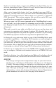
Section 1: Read Me First! How this manual can get you out on the road, fast! Welcome to the exciting world of GPS satellite navigation! We know you're anxious to begin finding your way with this space-age technology, but we have a favor to ask. Before you grab the GlobalMap Baja® and begin installing it, please give us a moment or two to explain how our manual can help you get the best performance from your highresolution, high-performance GPS+WAAS chart recorder.
Section 3 contains short, easy-to-scan GPS lessons that follow one another in chronological order. They're all you'll need to know to find your way on the water or in the wilderness quickly. After you've learned the basics (or if you already have some GPS experience), you may want to try out some of the GlobalMap Baja's many advanced navigation features. That brings us to Section 4, Advanced GPS Operations. This section contains the rest of the unit's GPS command functions, organized in alphabetical order.
How Lowrance GPS Works You'll navigate faster and easier if you understand how the GlobalMap Baja scans the sky to tell you where you are on the earth — and, where you're going (But if you already have a working understanding of GPS receivers and the GPS navigation system, skip on ahead to Section 2, Installation & Accessories on page 9. If you're new to GPS, read on, and you can later impress your friends with your new-found knowledge.).
tape in a cassette tape recorder. You can save several different GPS data files, erase 'em and record new ones, over and over again. Like any computer file, these GPS Data Files (file format *.usr) can be shared between Lowrance GPS or sonar/GPS units or even personal computers. This GlobalMap Baja has one more thing in common with a personal computer.
the armed forces of the U.S. and its allies. Civilian use was also available at first, but it was less accurate because the military scrambled the signal somewhat, using a process called Selective Availability (SA). GPS proved so useful for civilian navigation the federal government discontinued SA on May 2, 2000, after the military developed other methods to deny GPS service to enemy forces.
GlobalMap Baja to determine direction of travel, you must be moving and the faster, the better. This is not to say that it won’t work at walking or trolling speeds — it will. There will simply be more "wandering" of the data shown on the display. GPS is plenty accurate for route navigation, but the U.S. Federal Aviation Administration has special needs for aircraft traffic control that go beyond basic GPS.
Arrow Keys The arrow keys control the movement of dotted cross-hair lines on your mapping screen called the cursor. The arrow keys help you move around the menus so you can execute different commands. They are represented by symbols like these, which denote the down arrow key, the up arrow, the left arrow and the right arrow: ↓ ↑ ← →. Keyboard The other keys perform a variety of functions. When the text refers to a key to press, the key is shown in bold, sans serif type.
Notes 8
Section 2: Installation & Accessories Preparations You can install the GPS system in some other order if you prefer, but we recommend this installation sequence: Caution: You should read over this entire installation section before drilling any holes in your vehicle or vessel! 1. Determine the approximate location for the GPS unit, so you can plan how and where to route the cables for the antenna and power. This will help you make sure you have enough cable length for the desired configuration. 2.
You need to select an antenna installation location that has a clear, unobstructed view of the sky. After the module is installed, connect it to the unit. The LGC-3000 can communicate with your GPS unit either directly (using the supplied extension cable) or through a NMEA 2000® network. NOTE: See the module’s instruction sheet, publication part number 9880154-651, for complete installation instructions.
NOTE: There are two basic power connection options, which are shown in the following two diagrams. Read the following instructions carefully to determine which power connection applies to your unit. Depending on your configuration, you may not use all of these wires. Caution: All of the wires in the power/data cable have bare ends for easier installation. The bare ends on any unused wires could cause an electrical short if left exposed.
this unit could be damaged to a point that it is irreparable and could even cause harm to the user when not properly fused. Failure to use a 3-amp fuse will void your warranty. If possible, keep the power cable away from other boat wiring, especially the engine's wires. This will provide the best isolation from electrical noise. If the cable is not long enough, splice #18 gauge wire onto it. The display power cable has two wires, red and black. Red is the positive (+) lead, black is negative (–) or ground.
The network and any NMEA 2000 devices, including the GPS module, will not operate unless the NMEA 2000 Power Cable is connected to power. The NMEA 2000 power cable must be connected to power even if your only NMEA 2000 device is the GPS module and it is connected to the display unit's Network socket. (However, never connect multiple power sources to a NMEA 2000 network. If you have a network that is already powered, see diagram B.
use the method shown in Power Diagram B above. Never attach two power sources to a single NMEA 2000 bus. If you do need to power your NMEA 2000 bus, attach the NMEA 2000 Power cable to an accessory switch as indicated in power diagram A. The NMEA 2000 Power cable's red wire should be attached (with provided 3-amp fuse) to the positive (+) terminal. The NMEA 2000 Power cable's black and shield wires should both be attached to the negative (–) terminal.
Network port on display unit Double T Connector Extension cable 120-ohm terminator 120-ohm terminator Extension cable LGC-3000 LGC-3000 and display unit as an expandable NMEA 2000 network. The diagram above has a double T connector with two 120-ohm terminators — one at each end of the connector.
Com-1 To Unit Yellow (Transmit) Receive Orange (Receive) Transmit Shield (Ground) Ground To Other Device Com-1 wiring to exchange information with another device. Com-2 To Unit Blue (Transmit) Receive Green (Receive) Transmit Shield (Ground) Ground Com-2 wiring to exchange information with another device.
Ethernet (for later expansion) Network Power/Data NMEA 0183 Data cable (five wires) Double T-connector 120-ohm female terminator 120-ohm male terminator Display unit power cable NMEA 2000 Power cable Extension cables LGC-3000 GPS Module Cable connections, GlobalMap Baja 840c.
Expanding to a NMEA 2000 Network A network bus is an installed and operational network cable (backbone) running the length of your boat, already connected to a power supply and properly terminated. Such a bus provides network connection nodes at various locations around your boat. The NMEA 2000 network is similar to the telephone wiring in a house. If you pick up a phone in your living room, you can hear someone talking into the phone in the bedroom.
NOTE: If you have a double T Connector on your network that is not attached to a device, you must cap the unused connector with a NMEA 2000 cap. This will protect the pin connectors from corrosion. The NMEA 2000 cap looks like a terminator, but has "Cap" stamped into the connector housing. Adding a Network Node You can add a node to any existing connection, anywhere along the network backbone.
NOTE: You do not need a Bus Adapter Cable with this unit if you use an approved Devicenet NMEA 2000 connector. Approved Devicenet NMEA 2000 connectors work with Lowrance red connector display units and components, so no adapter cables are needed. Mounting the Unit: Bracket You can install the GlobalMap Baja on the top of a dash with the supplied gimbal bracket. If you use the supplied bracket, you may be interested in the optional R-AM® bracket mounting system.
Cable hole Screw mounting hole Front Install the gimbal bracket. Place the bracket so the arms slope toward the front of your unit. Once a location is determined, use the bracket as a template and mark the mounting holes and the hole for the cables. Drill a 1-inch (25.4 mm) hole in the dash for the power, transducer and antenna cables. Screw the bracket to the mounting surface.
To pass all connectors through the 1" hole, first pass the antenna connector up through the hole from under the dash. Next, pass the power cable's bare-wire end down though the hole from the top. If you wish, you can fill in the hole around the cables with a good marine caulking compound. No matter what type of installation you prefer, be sure to leave enough slack in the cables to allow tilting or swiveling the unit. Attach the unit to the gimbal bracket using the supplied gimbal knobs and washers.
MMC groove for card removal Thumb screw Insert card face up, this way Memory card compartment with a 16 MB MMC card installed. To remove an MMC or SD Card 1. Open the card compartment door by unscrewing the thumb screw. The screw should only be finger tight. If it was over-tightened, use a thumbnail, a coin or a screwdriver to open the door. 2. Use the ball of your finger or thumb and press down in the center of the card, then drag the MMC from the slot.
MapCreate™ 6 CD-ROM, left; MMC card reader for USB ports, right. Now that you have your GlobalMap Baja installed, move on to Section 3, Basic GPS Operations. There, we'll present a series of step-by-step tutorials to teach you the basics of GPS navigation. Face Cover Your unit comes with a white protective cover that snaps on and off the front of the unit. This cover is intended for use when your unit and the vehicle it's mounted in are idle.
Section 3: Basic GPS Operations This section addresses the unit's most basic GPS operations. The tutorials presented in Sec. 3 follow a chronological order. Sec. 4, Advanced GPS Operations, will discuss other more advanced functions and utilities. Material in Sec. 4 is arranged in alphabetical order. Before you turn on the unit and find where you are, it's a good idea to learn about the different keys, the four Page screens and how they all work together.
3. MENU – Press this key to show the menus and submenus, which allow you to select a command or adjust a feature. This also accesses search functions for streets, intersections, addresses and highway exits. 4. ARROW KEYS – These keys are used to navigate through the menus, make menu selections, move the map cursor and enter data. 5. ENT/ICONS (Enter & Icons) – This key allows you to save data, accept values or execute menu commands. It is also used to create event marker icons. 6.
Main Menu. The Main Menu commands and their functions are: Screen command: changes the contrast or brightness of the screen. Sounds command: enables or disables the sounds for key strokes and alarms and sets the alarm style. Transparency command: adjusts the level of transparency for menus. Alarms command: turns GPS alarms on or off and changes alarm thresholds. Route Planning command: used to plan, view or navigate a route. My Trails command: shows, hides, creates and deletes plot trails.
Pages The unit has four Page displays that represent the four major operating modes. They are the Satellite Status Page, the Navigation Page, the Map Page and Radar Page (for more information on Radar see additional materials). They are accessed by pressing the PAGES key, then using → or ← to select a Page (Clear the Pages Menu by pressing EXIT.). Pages Menu showing some Map display options.
The Satellite Status Page. This screen shows a graphical view of the satellites that are in view. Each satellite is shown on the circular chart relative to your position. The point in the center of the chart is directly overhead. The small inner ring represents 45° above the horizon and the large ring represents the horizon. North is at the top of the screen. You can use this to see which satellites are obstructed by obstacles in your immediate area if the unit is facing north.
The navigation screen looks like the one below when you're not navigating to a waypoint or following a route or trail. Your position is shown by an arrow in the center of the screen. Your trail history, or path you've just taken, is depicted by the line extending from the arrow. The arrow pointing down at the top of the compass rose indicates the current track (direction of travel) you are taking.
Bearing window shows the compass direction straight to the destination from your location at the moment. Distance shows how far it is to the waypoint you're navigating toward. The Off Course window shows the current cross track error. This shows the distance you are off-course to the side of the desired course line. The course line is an imaginary line drawn from your position when you started navigating to the destination waypoint.
In the example above, the driver is headed north (a 355º track) toward a waypoint 355º (bearing) away. The cross track error range (white corridor) is 0.20 miles either side of the course. The driver is headed toward trail waypoint 4, which is 0.14 miles away. The vehicle is virtually on course (off course 1 foot to the right). Traveling at a speed of 27 mph, the driver will arrive at the waypoint in 19 seconds.
Map Page opening screen (left). Zoomed to 100 miles (center) and zoomed to 15 miles (right). Over Zoomed means you have reached the detail limits in an area covered only by the basic background map. Zooming in any closer will reveal no more map details because a highdetail custom map has not been loaded on the MMC. If you're using only the factory-loaded background map, the maximum zoom range for showing additional map detail is 20 miles.
MapCreate custom maps include massive amounts of information not found in the background map. MapCreate contains: the searchable Points of Interest database, all the minor roads and streets, all the landmark features (such as summits, schools, radio towers, etc.); more rivers, streams, smaller lakes and ponds and their names. What's more important is the large-scale map detail that allows your GPS unit to show a higher level of position accuracy.
The Pages Menu also offers several map display options under the Map Page category. To access them, press PAGES|← or→ to MAP|↓ to Option|EXIT. GlobalMap Baja Digital Data page (left) and Two Position Formats page (right). Pages Menu with Two Maps option selected (left). Map Page with two map windows (right). The right map is active. In pages that have two major windows (such as two maps) you can toggle back and forth between the two windows by pressing PAGES|PAGES.
just follow the steps above (Most dual-window displays use half the screen for each window by default.). You can also use the Reset Options command to revert to the factory default. Map Menu with Resize Window command selected (left). Resize Window command is active (center). Pressing the ← → or ↑ ↓ keys allows you to resize the windows from side to side or stack them one on top of the other (right). The following page contains a 12-step quick reference for the most basic GPS operations.
GPS Quick Reference Start outdoors, with a clear view of the open sky. As you practice, try navigating to a location at least a few blocks away. While you're learning, navigation in too small an area will constantly trigger arrival alarms. 1. Connect the unit to electric power and the antenna module. Make sure the MMC is in. (See complete installation details beginning on page 9.) 2. To turn on the GlobalMap Baja, press and release PWR key. 3.
Find Your Current Position Finding your current position is as simple as turning the GlobalMap Baja on. With an unobstructed view of the sky, the unit automatically searches for satellites and calculates its position in approximately one minute or less. If for some reason satellite acquisition takes longer, you may be inside a structure or vehicle or in terrain that is blocking signal reception.
POI pop-up name box Cursor line Distance measured by cursor Selected airport Cursor line The selected airport is 4.25 miles away, to the northwest. Selecting Any Map Item with the Cursor 1. Use the zoom keys and the arrow keys to move around the map and find the item you wish to select. 2. Use the arrow keys and center the cursor cross-hair on the desired object. On most items, a pop-up box will give the name of the selected item.
Category Selection menu (left); list of the nearest restaurants (right). 4. If you wish, you could scroll ↑ or ↓ here to select another restaurant, but for now we will just accept the nearest one. Press ENT. 5. The POI information screen appears (This is how you can use the GlobalMap Baja as a business phone directory!). If you wanted to navigate there, you could press ENT, since the GO TO command is highlighted. But we just want to see it on the map, so press ↓ to FIND ON MAP|ENT.
Map screen showing Find Waypoint, the result of a restaurant search. NOTE: Search works from mapping and POI data loaded in the GlobalMap Baja. If you do not have a high-detailed custom map (containing POI data) for the area you are searching loaded on the MMC, you may not find anything. Set a Waypoint A waypoint is simply an electronic "address," based on the latitude and longitude of a position on the earth.
Step 1. Step 2. Step 4. Step 3. Sequence for setting a waypoint. Step 1: while traveling, quickly press WPT twice to call up Find Waypoint screen (seen in Step 2) and set a point. Step 3: a message says the waypoint has been saved. Step 4: vehicle continues on its way; number waypoint symbol is visible on map. NOTE: The Quick Save method uses the default waypoint symbol until you edit an existing waypoint and change its symbol (Edit Waypoint Symbol is described in Sec. 4.).
Create Waypoint by Entering a Position 1. Press WPT|→ to SUBCATEGORY column|↓ to NEW|ENT. 2. Press ↓ to ENTERED POSITION|ENT|→ to CREATE|ENT. 3. Press → to LATITUDE|ENT. Enter the latitude by pressing ↑ or ↓ to change the first character, then press → to the next character and repeat until the latitude is correct. Press ENT. 4. Press ↓ to LONGITUDE|ENT. Enter the longitude by pressing ↑ or ↓ to change the first character, then press → to the next character and repeat until the longitude is correct.
Waypoint Course line (dotted) Trail line (solid) Off course range, set at 0.20 mile Destination name GlobalMap Baja navigation Page, navigating toward waypoint 004 and leaving a trail. Set Man Overboard (MOB) Waypoint One of boating's most terrifying events is having a friend or family member fall overboard. This situation can be deadly on any body of water. It's particularly dangerous at night or if you're out of sight of land.
Navigating to Man Overboard: navigation page (left) and Map Page (right). The victim is astern of the vessel; the GPS shows which direction to steer to for the rescue. The man overboard position is also stored in the waypoint list for future reference. It can be edited the same as any other waypoint. To cancel navigation to MOB, press MENU|MENU|↓ to CANCEL NAVIGATION|ENT|← to YES|ENT. The GlobalMap Baja stops showing navigation information.
Navigate to cursor. In this example, the cursor is positioned on the town of Oologah, Oklahoma. 3. Press MENU|ENT and the GlobalMap Baja will begin navigating to the cursor location. The Map Page will display a dotted line from your current position to the cursor position. The Navigation Page displays a compass rose showing navigation information to your destination. See the following examples.
After you have looked up an item with the Find Waypoint command, use the → to make sure the GO TO command is highlighted at the top of the screen, then press ENT. The GlobalMap Baja begins showing navigation information to the item. To cancel navigation, press MENU|MENU|↓ to CANCEL NAVIGATION|ENT|← to YES|ENT. The unit stops showing navigation information. Creating and Saving a Trail A trail, or plot trail, is a string of position points plotted by the GlobalMap Baja as you travel.
3. Press ↓ → to ACTIVE|ENT. This unchecks the Active option. 4. To return to the previous page, press EXIT|EXIT|EXIT|EXIT. As you left the Edit Trail menu, you will notice that a new trail was started with a new sequential number. In the example below, the new trail is number 15, showing zero points. Note that Trail 14 is inactive, but it is still visible on the map. A new trail, Trail 15, is created when Trail 14 is set to inactive.
To turn on trail display: 1. Press MENU|MENU|↓ to MY TRAILS|ENT. 2. Press ↓ to enter the Saved Trail list, then use ↑ or ↓ to select the desired Trail Name|ENT. 3. Press ↓ → to ACTIVE|↓ to VISIBLE|ENT. To return to the previous page, press EXIT|EXIT|EXIT|EXIT. Navigating Trails There are three methods for following a trail: visual trailing, navigating a trail (forward) and backtracking a trail (backward). Try each method to see which you prefer. Visual trailing is the simplest method.
NOTE: If you are already located at or near the beginning of your trail, the arrival alarm will go off as soon as you hit Enter. Just press EXIT to clear the alarm. 5. Begin moving and let your GlobalMap Baja guide you. 6. When you reach your destination, be sure to cancel your navigation: press MENU|MENU|↓ to CANCEL NAVIGATION|ENT. The unit asks if you're sure. Press ←|ENT. Figure 1. Figure 2. Figure 3. Figure 4. Navigate a trail menu sequence: Fig. 1, My Trails command. Fig. 2, Trails Menu. Fig.
Present position arrow North Ï Dotted trail line Trail point Navigate trail, map views: driver is northbound heading straight toward trail point 6 (left). northbound driver has reached point 6 (right) and has turned west to follow trail.
NOTE: If you are already located at or near the end of your trail, the arrival alarm will go off as soon as you hit ENT. Press EXIT to clear the alarm and proceed. 5. Begin moving and let your GlobalMap Baja guide you. 6. When you reach your destination, be sure to cancel your navigation. Press MENU|MENU|↓ to CANCEL NAVIGATION|ENT. The unit asks if you're sure. Press ←|ENT.
The Transfer My Data submenu asks if you want to save data to the MMC or load data from the MMC into the unit's memory. 2. The Transfer My Data menu includes a message that tells you if a MMC is present or not. If no MMC is present, you must insert a card to activate the Load or Save commands. To transfer data from the GlobalMap Baja to the MMC press ENT (for SAVE). To transfer data from the MMC to the GlobalMap Baja press → to LOAD|ENT. 3.
4. Loading to unit memory: There may be more than one GPS Data File (*.USR) on the card. To select a file, press ENT to activate the selection box, use ↓ or ↑ to highlight the file, then press ENT to accept the selection. Next, press ↓ to LOAD DATA|ENT. The unit will display a completion message when the data transfer is finished. To return to the Page view, press EXIT repeatedly. Figure 1. Figure 2. Figure 3. Figure 4.
NOTE: If you do no have a MMC or SD card already in the unit, the data information will automatically save to the unit's hard drive. To retrieve the saved data information: 1. MENU | MENU| ↓ to BROWSE FILE | ENT| ENT 2. Scroll through the list of files to find the one you want 3. Press ENT|↓ to PLAY|ENT|EXIT Cancel Navigation You can turn off any of the navigation commands after you reach your destination or at any other time by using the Cancel Navigation command.
Notes 56
Section 4: Advanced GPS Operations Find Distance to Another Location 1. While on the Map Page press MENU|↓ to FIND DISTANCE|ENT. 2. To check the distance to a location, center the cursor over the desired position. A rubber band line appears, connecting your current position to the cursor's location. The distance along that line will appear in a pop-up box. The box also shows the bearing to the location. 3. Press EXIT to return to regular operation. The distance from Dallas to Little Rock is 292.
You can create an icon at the cursor position on the map, or at your current position while you are navigating. Create Icon on Map 1. Use the arrow keys to move the cursor to the location you want to mark with an icon. 2. Press ENT and the screen shows a Select Icon Symbol menu. 3. Press ← or ↑ or → or ↓ to select your icon symbol, then press ENT. The icon appears on the map. Cursor selects icon location (left); Select Icon Symbol menu (center); Boat Ramp icon on map (right).
The Delete All Icons command will ask if you are sure. Press ← to YES|ENT. All icons will be deleted from the map. The Delete by Symbol command will launch the Select Symbol menu. Press ← or ↑ or → or ↓ to select the symbol to delete, then press ENT. A message appears saying all icons with the selected symbol have been deleted. The Delete from Map command will prompt you to move the cursor over an icon to select it. After selecting the icon, press ENT and it disappears from the map.
Routes Created in the GlobalMap Baja You can create a route by selecting existing waypoints from the waypoint list or you can set a series of route waypoints on the map with cursor arrows and the Enter key. In this example, we'll create a route from the map. 1. From the NAVIGATION PAGE, press MENU|ENT or from the MAP PAGE, press MENU|MENU|↓ to ROUTE PLANNING|ENT. Route Planning command on Main Menu (left), will open the Route List screen (right). Copy one of the above trails 2.
1. 3. 2. Route creation sequence (left to right): Fig. 1. Set route waypoint (1) at 11th St. & 145th Ave. Fig. 2. Move cursor north to set point (2) at 145th & Admiral. Fig. 3. With point (2) set, move cursor east to mark interstate on-ramp with waypoint (3). In figures 2 and 3, notice the rubber band line extending from the previously set waypoint to the cursor. This line will become the course for the route. 4. 5. 6. Route creation sequence, continued: Fig. 4. Point (3) set at on-ramp turn. Fig. 5.
Tip: You can also delete all routes at once: 1. From the NAVIGATION PAGE, press MENU|ENT or from the MAP PAGE press MENU|MENU|↓ to ROUTE PLANNING|ENT. 2. Press ↑ → to DELETE ALL|ENT|← to YES|ENT. Edit a Route You can edit the route name if you wish. 1. From the NAVIGATION PAGE, press MENU|ENT or from the MAP PAGE press MENU|MENU|↓ to ROUTE PLANNING|ENT. 2. Press ↓ to route name|ENT|↑ to name | ENT. 3.
Navigate a Route 1. From the NAVIGATION PAGE, press MENU|ENT or from the MAP PAGE, press MENU|MENU|↓ to ROUTE PLANNING|ENT. Route Planning command on Main Menu (left); Routes menu (center); Edit Route menu (right) with navigate command is selected. 2. Press ↓ to select route name|ENT|↓ to NAVIGATE|ENT. 3. Upon arrival at your destination, cancel navigation: press MENU|MENU|↓ to CANCEL NAVIGATION|ENT|← to YES|ENT.
Figure 1. Figure 2. Figure 3. Figure 4. Navigating along a route: Fig. 1 shows the GlobalMap Baja Navigation Page at the start of a route, heading straight for the first waypoint (Wpt 1). In Fig. 2, the traveler has arrived at Wpt 1; the arrival alarm has been triggered and the bearing arrow on the compass rose has turned to point east, toward Wpt 2. In Fig. 3 the traveler has turned east on his new course and is heading straight for Wpt 2, which is 2.15 miles away. Fig.
Edit a Trail Name To edit a trail name: press MENU|MENU|↓ to MY TRAILS|ENT|↓ to trail name|ENT|ENT. Press ↑ or ↓ to change the first character, then press → to the next character and repeat until the name is correct. Press ENT then EXIT|EXIT|EXIT|EXIT to return to the previous page display. Tip: You can quickly call up the Edit Trail menu by selecting a trail on the map with the cursor. Simply move the cursor over a trail and a pop-up box appears. Press WPT and the Edit Trail menu opens.
Edit Trail Menu with Pattern option selected (left). Edited trail with dotted line pattern (right). transparency Utilities Utilities are useful tools for traveling or for outdoor activities. Alarm Clock To get to the alarm clock menu: press MENU|MENU|↓ to TIMERS|ENT|↓ to ALARM CLOCK|ENT. Sun/Moon Rise & Set Calculator To get to the Sun/Moon menu: press MENU|MENU|↓ to SUN/MOON CALCULATIONS|ENT. Trip Calculator To get to the Calculator menu: press MENU|MENU|↓ to TRIP CALCULATOR|ENT.
Edit a Waypoint Waypoint Name To edit waypoint name: 1. Press WPT|ENT|ENT|ENT|↓ to waypoint name|ENT|↓ to EDIT WAYPOINT|ENT|ENT. 2. Press ↑ or ↓ to change the first character, then press → to the next character and repeat until the name is correct. Press ENT then EXIT|EXIT|EXIT|EXIT to return to the previous page display. Waypoint Symbol To edit waypoint symbol: 1. Press WPT|ENT|ENT|ENT|↓ to waypoint name|ENT|↓ to EDIT WAYPOINT|ENT|↓ to CHOOSE SYMBOL|ENT. 2.
Set a Waypoint by Projecting a Position This feature sets a waypoint at a point located a specific distance and bearing from a reference position. The reference position may be a map feature or can be selected from your waypoint or Points of Interest lists. 1. Press WPT|→ to SUBCATEGORY column|↓ to NEW|ENT. 2. Press ↓ to PROJECTED POSITION|ENT|→ to CREATE|ENT. 3. Press → to CHOOSE REFERENCE|ENT. Use ↑ and ↓ to select a waypoint, map feature or Point of Interest.
Section 5: System & GPS Setup Options Alarms This unit has three GPS alarms. The factory default setting has all the alarms turned on. You can turn the alarms off and on and change their distance settings. You can set an arrival alarm to flash a warning message and sound a tone when you cross a preset distance from a waypoint. For example, if you have the arrival alarm set to 0.1 mile, then the alarm will flash a message when you come within 0.1 mile of the recalled waypoint.
3. To change distance settings, scroll ↓ or ↑ to select the desired category, then press →|ENT to activate the distance dialog box. Press ↑ or ↓ to change the first character, then press → to the next character and repeat until the name is correct. 4. When your adjustments are finished, return to the last page displayed by repeatedly pressing EXIT. IMPORTANT ALARM NOTES: Anchor Alarm — The anchor alarm may be triggered even when you're sitting still. This typically happens when using small (less than 0.
GPS Auto Search on the GlobalMap Baja Satellite Status Menu. Here's how to put the unit into auto search mode: 1. Press PAGES until you are on the Satellite Status screen. 2. Press MENU|↓ to GPS AUTO SEARCH|ENT|← to YES|ENT. Check MMC Files and Storage Space To check MMC Files: Press MENU|MENU|↓ to BROWSE FILES|ENT. Main Menu (left), MMC File Browser (right). Communications Port Configuration The unit has two NMEA 0183 version 2.0 compatible communication ports, or com ports for short.
System Setup Menu with Communications Port highlighted (left) and Communications Port menu (right). For assistance in configuring the unit to communicate with another device, consult the factory. Customer service phone numbers are in the back of this manual. Also see the entry below for to Configure NMEA. To set Com Port Configuration: 1. Press MENU|MENU|↓ to SYSTEM SETUP|ENT. 2. Press ↓ to COMMUNICATIONS PORT|ENT. Configure NMEA You can configure the unit to use specific NMEA sentences. 1.
Menus for changing coordinate system. To get to Coordinate System Selection: 1. Press MENU|MENU|↓ to GPS SETUP|ENT. 2. Press ↓ to COORDINATE SYSTEM|ENT. This unit can show a position in degrees (36.14952°); degrees, minutes and thousandths of a minute (36° 28.700'); or degrees, minutes, seconds and tenths of a second (36° 28' 40.9").
To setup Loran TD: NOTE: If the Loran TD conversion is chosen, you must enter the local Loran chain identification for the master and slaves. Do this by selecting "Setup Loran TD" at the bottom of the "Coordinate System" menu, press ENT, and select the ID. Press EXIT to clear this menu. Configure Loran TD menu. Map Fix Map Fix is used with charts or maps. This system asks for a reference position in latitude/longitude, which you take from a marked location on the map.
1. Press MENU|MENU|↓ to GPS SETUP|ENT. 2. Press ↓ to COORDINATE SYSTEM|ENT. 3. Press ↓ to SETUP MAP FIX|ENT. The following screen appears, and MAP SCALE is highlighted. Press ENT and enter the map's scale. This is generally at the bottom of a paper map. It's shown as a ratio, for example 1:24000. Press EXIT and the unit returns to the Configure Map Fix screen. Configure a map fix so the GlobalMap Baja can find your position on a printed chart or topographical map.
To change the information displayed in a data box: On the Page display you wish to change, press MENU|↓ to CUSTOMIZE|ENT| ENT. You'll see a list of categories with "+" or "–" symbols next to each category. A category with a "+" is expandable, meaning its contents are hidden. Customize Menu, with the GPS Data category expanded. Selecting the category name and pressing ENT will show the category's contents, so you can choose items within it.
To get to the GPS Simulator: 1. Press MENU|MENU|↓ to SYSTEM SETUP|ENT. 2. Press ↓ to SIMULATORS|ENT. The GPS Simulator Menu appears. 3. Press ↓ to GPS SIMULATOR ON | ENT GPS Setup Menu (left); GPS Simulator menu (right). Make the desired settings, then turn the simulator on by highlighting the GPS SIMULATOR ON box and pressing ENT key. Press EXIT|EXIT|EXIT to clear this menu. A message and tone appear periodically, warning you that the simulator is on.
4. Press EXIT to turn off the steering and speed boxes. The unit will now automatically "steer" along the trail or route. When you arrive at your "destination," cancel navigation as you normally do. Tip: You can pick any spot on the map to begin your simulation session by using the Initialize GPS command. This makes your unit think it's located at the position you select. See the following entry.
which display latitude and longitude grid lines or range rings on the map. This menu lets you select Navionics Maps. For instructions, see the Navionics Charts entry in this section. To get to Map Data: From the Map Page, press MENU|↓ to MAP DATA|ENT. Map Menu (left) and Map Data Menu (right). Earth Map Detail From the Map Page, press MENU|↓ to MAP DATA|ENT. Press ENT to check to select the level of map detail you prefer. Use ↑ ↓ to choose off, low, medium or high, then press EXIT to the page display.
Trackline Extension window are two check boxes (Show Time and Show Distance) which allow you to turn on or off the time and/or distance settings. To set trackline extension: From the Map Page, press MENU|↓ to MAP DATA|ENT. Press ↓ to TRACKLINE EXTENSION|ENT. Use ↑ ↓ to select the desired distance setting and press ENT. Presentation Mode From the Map Page, press MENU|↓ to MAP DATA|ENT. Press ↓ and → to PRESENTATION MODE|ENT. Use ↑ ↓ to choose the desired depth and press ENT.
Map Datum Selection Maps and charts are based on a survey of the area that's covered by the map or chart. These surveys are called "Datums." Maps that are created using different datums will show the same latitude/longitude in slightly different locations. All datums are named. The GPS system is based on the WGS-84 datum, which covers the entire world. Other datums may also cover the entire world, or just a small portion of it. By default, your position shows using the WGS-84 datum.
Map menu (left) and Map Categories Drawn menu (right). Map Orientation By default, this receiver shows the map with north always at the top of the screen. This is the way most maps and charts are printed on paper. In Track Up mode, map shows "N" and arrow to indicate north. Map orientation shown in north up (left) and track up (right). This is fine if you're always traveling due north.
To change map orientation: from the Map Page, press MENU|↓ to MAP ORIENTATION|ENT. Use ↑ or ↓ to select the desired mode, then press ENT. Press EXIT|EXIT to return to the page display. Map Menu (left) and Map Orientation menu with the North Up map orientation option selected (right). NauticPath™ USA Marine Charts Your unit can display NauticPath electronic charts on MMCs. They work just like a MapCreate custom map on a MMC.
2. Press WPT to display the Note Information screen. 3. To scroll through the Chart Note screen, use ↑ ↓ arrow keys to read the information. To return to the main page display, press EXIT repeatedly. Entrance to Aransas Pass on a NauticPath chart with 8-nautical mile zoom (left). Remaining images (left to right): same position at 4nautical mile, 1-nautical mile and 0.3- nautical mile zoom ranges.
3. To scroll through the service information window, use ↑ ↓ to see the types of services available. To return to the main page display, press EXIT repeatedly. Port Services information. Tidal Current Information NauticPath charts contain Tidal Current information, represented at large zoom ranges by a box icon with the letter "C." These icons will appear when you are zoomed in to a 6-mile range. The icon stands for a Tidal Current Station location. An example is displayed on the right.
Cursor lines Tidal Current Station icon in animated mode NauticPath chart showing Tidal Current Station icon selected by cursor (left). Tidal Current animated icon at .8-nautical mile range. Current Time Line Slack Water Line Velocity Scale Tide Tables Current Information screen. The Tidal Current Information screen displays daily tidal current data for this station on this date at the present time.
To select another date: 1. Use ← → to highlight month, day or year, then press ENT. 2. Use ↑ ↓ to select the desired month, day or year and press ENT. To clear the information screen, press EXIT. Tide Information NauticPath charts contain Tidal Information, represented at large zoom ranges by a box icon with the letter "T." These icons will appear when you are zoomed in to a 6-mile range. The icon stands for a Tidal Station location. An example is displayed at right.
Current Time Line Height Scale MLLW Line Tide Table Tide Information screen. The Tide Information screen displays daily tidal data for this station on this date at the present time. The graph at the top of the screen is an approximate view of the tidal range pattern for the day, from midnight (MN) to noon (NN) to midnight (MN). The dotted line across the graph is the Mean Lower Low Water line (MLLW).
To display a Navionics chart: 1. Install the Navionics MMC in the memory card compartment and turn on the unit. (For full card install instructions, see Sec. 2.) 2. From the Map Page, press MENU|↓ to MAP DATA|ENT|↓ to MAP CHOICE|ENT. Select the Map Name, then press ENT|EXIT|EXIT. Navionics Map Choice highlighted. Press Ent to select the desired Navionics map from the Map Choice drop down box. WARNING: You should never format the MMC containing your Navionics chart.
commands is that Customize changes only the digital data boxes on a screen, and Overlay Data changes only the information floating on the screen without a box. See Customize Page Displays, on page 75 for information on customizing data boxes. Overlay Data highlighted on GPS menu (left). The Data Viewer menu with the Navigation category expanded. To overlay information on your screen: 1. While on the Navigation Page or a Map Page, press MENU|↓ to OVERLAY DATA|ENT | ENT. 2.
From Overlay Data Shown menu (left) press ENT to see Data Viewer (center). Select a category and press ENT. Bearing, Closing Speed and Off Course have been selected from the Navigation category. To remove overlaid data: 1. While on the Page that shows the item or items you want to remove, press MENU|↓ to OVERLAY DATA|ENT. 2. You'll see a list of the overlay data currently displayed. Select the item you want to remove from your display and press ENT|ENT to remove the data.
3. The data begins to flash on your screen. Use any combination of →, ←, ↑ and ↓ to move the data to a new location on the screen. 4. When satisfied, press EXIT|EXIT. To resize overlaid data: press MENU|↓ to OVERLAY DATA|ENT. This will bring up the Overlay Data Shown menu with a list of the current overlay data. Use → ← to toggle the size of the data between small, medium, large and enormous. When you are satisfied with the data size, press EXIT.
Gauge Setup Menu. There are four primary setup options in the analog menu: Themes, Tick Marks, Thresholds and Text. When working in the gauge setup menu, use ↓ ↑ and → ← to highlight the desired option, then press ENT. Pressing EXIT will take you back to the previous screen. NOTE: You can make gauges transparent from all the setup menus except Text Setup. Themes setup allows you to change gauge style, color scheme, and needle style.
Minimum or Maximum Tick controls how many tick marks will be displayed on the gauge. If you set the minimum tick to 1 and the max tick to 10, there will be 10 tick marks between 0 and 10, 10 and 20 and so on. In the case of a speedometer, that's one tick for one mile per hour. If you change the minimum tick to 2 and leave the maximum tick at 10, you'll have one tick for every two miles per hour. That's five ticks between 0 and 10, 10 and 20 and so on.
NOTE: The Analog setup menus allow you to make gauges transparent. Despite their transparency, the gauges take up much of the display screen. A display with a transparent track gauge (left). The screen on the right is displaying Track and speed gauges. Pop-up Help Help is available for virtually all of the menus on this unit. By highlighting a menu item and leaving it highlighted for a few seconds, a "pop-up" message appears that describes the function of the menu item. This feature is on by default.
Reset Options To reset all features to their factory defaults: Press MENU|MENU|↓ to SYSTEM SETUP|ENT|↓ to RESET OPTIONS|ENT|← to YES|ENT. NOTE: Reset Options does not erase waypoints, routes, icons or plot trails. Reset Options command (left) and the Reset Options menu (right). Screen Contrast and Brightness To access the Screen menu, press MENU|MENU|ENT. Once in the Screen menu: To adjust the display's contrast: The CONTRAST slider bar is already selected. Press → or ← to move the bar.
To adjust the screen's display mode: Press ↓ to DISPLAY MODE|ENT|press ↑ or ↓ to select mode|EXIT. Display Mode menu. Set Language This unit's menus are available in 10 languages: English, French, German, Spanish, Italian, Danish, Swedish, Russian, Dutch and Finnish. To select a different language: 1. Press MENU|MENU|↓ to SYSTEM SETUP|ENT. 2. Press ↓ to SET LANGUAGE|ENT. 3. Use ↓ or ↑ to select a different language and press ENT. All menus now appear in the language you selected.
To set the Day: Press → to DAY|ENT. Press ↑ or ↓ to select the day, then press ENT. To set the Year: Press → to YEAR|ENT. Press ↑ or ↓ to select the year, then press ENT. Time Settings Menu. To Set Time Format: Press ↓ to the Time Format window. Just highlight the option you prefer — 12 or 24 hour — and press ENT. To Set Date Format: Press ↓ and → to modify the Date Format. There are three options: Month/Day/Year, Day/Month/Year and Year/Month/Day.
2. With the option highlighted, press ENT to uncheck it (turn off) and check it (turn on). After the option is set, press EXIT|EXIT to return to the page display. 3. You can return to this command and press ENT again to turn on the feature. Software Version Information From time to time, Lowrance updates the operating system software in some of its products. These software upgrades are usually offered to customers as free downloads from our web site, www.lowrance.com.
Sounds command (left); The Sounds menu (right). Once in the Sounds menu: To set Key Press Sounds: With the option highlighted, press ENT to check it (turn on) and uncheck it (turn off). After the option is set, press EXIT|EXIT to return to the page display. To set Alarm Sounds: Press ↓ to ALARM SOUNDS. With the option highlighted, press ENT to check it (turn on) and uncheck it (turn off). After the option is set, press EXIT|EXIT to return to the page display. To set Alarm Volume: Press ↓ to VOLUME.
Trail Options There are several options you can use with trails. Some affect all trails, other options can be applied to a particular trail. You can change the way trails are updated, you can display or hide trails, make them flash, create a new trail, delete a trail, etc. General Trail Options To access the Trails Menu: Press MENU|MENU|↓ to MY TRAILS|ENT. Main Menu (left), Trails Menu (center) and Trail Options menu (right).
range from 0.01 mile/nm/km to 9.99 mile/nm/km. The default is 0.10 miles. With one of the Update Criteria selected, use the cursor arrows to highlight either the UPDATE RATE or UPDATE DISTANCE data entry boxes and press ENT. Press ↑ or ↓ to change the first character, then press → to the next character and repeat until the entry is correct. Press EXIT to return to the Trail Options Menu. Trail Options menu: Update Time Rate setting (left) and Update Distance setting (right).
New Trail To manually start a new trail, in the Trails Menu, make sure NEW TRAIL is highlighted and press ENT|EXIT. Trail Visible/Invisible and Other Trail Options The name, maximum number of points in the trail, activity, and visibility are all changed on the Edit Trail menu screen. The Active setting determines whether or not the unit is recording new points for a particular trail. On the Edit Trail menu, press ↓ then → to highlight the Active and/or Visible checkboxes.
Units of Measure This menu sets the speed and distance (statute or nautical miles, meters), depth (feet, fathoms, or meters), temperature (degrees Fahrenheit or Celsius) and heading (true or magnetic) units. To change units: Press MENU|MENU|↓ to SYSTEM SETUP|ENT|ENT. The Units of Measure menu. To set Speed/Distance Unit of Measure: Press ENT then ↑ or ↓ to change the Speed/Distance unit, then press ENT. After the option is set, press EXIT|EXIT|EXIT to return to the page display.
Section 6: Searching NOTE: The background map loaded in your unit's permanent memory lets you search for some land features, including cities and lakes. For a full set of searchable land features, including landmarks, streets, addresses, highway exits and Points of Interest, you must load your own high-detail custom map produced with our MapCreate software. Or, you can use one of our plug and play map options such as FreedomMaps, Fishing HotSpots or NauticPath.
Find Address Menu. 3. To enter an address number, press ↑ or ↓ to change the first number, then press → to move the cursor to the next number and repeat until the number is correct, then press ENT. 4. To enter a street name, press ↓ to STREET|ENT. There are two options: A. You can spell out the name in the top selection box. Press ↑ or ↓ to change the first letter, then press → to move the cursor to the next letter and repeat until the name is correct, then press ENT|ENT. B.
NOTE: We recommend you do not enter a city name unless the list is too large when searching without one. The GlobalMap Baja can actually search quicker without a city. Find city field (left); Search in particular city only option (center) and Find City by name (right). 6. When the necessary search fields are filled in, press ↓ to FIND ADDRESS|ENT. Your unit asks you to wait while it searches for the address. If an address is not in the database, a message appears saying the address could not be found. 7.
the map, press WPT. The POI's Waypoint Information window appears, with the Go To Waypoint command highlighted. If you want to navigate to the POI address, just press ENT|EXIT. Map Page showing location of the address on the map, highlighted by the cursor (left). The Address is a business in the POI database (center), so you can display the POI information window, then navigate to it. Address is not in the POI database (right), so the Waypoint key will not display any information for this address.
Find Interstate Highway Exits 1. From the Map Page, press MENU|↓ to HIGHWAY EXITS|ENT, which calls up the Find Exit menu. Find Highway Exits command (left) and Find Exit menu (right). 2. First, select a highway name by pressing ENT, which calls up the Find By Name menu. There are two highway search options: A. You can spell out the highway name in the top selection box.
Find Exit menu, with an exit selected in the Exit List. 4. In the Exit Information screen you have two choices. A. Press ENT to navigate or "Go To" the exit. B. Press →|ENT to find exit on the map. Go To Exit option (left) and Find On Map option (right). Tip: You can also look up some additional information on the Exit Services located near this exit. Press ↓ to SERVICES, then press ↓ or ↑ to select Service Name|ENT. Exit Information screen (left); general location and amenities information (right).
Find Map Places or Points of Interest (POI) 1. Press WPT, then use ↓ or ↑ to select a map place or POI category, then press ENT (To narrow your search, press → then press ↓ or ↑ to select a subcategory before pressing ENT). You will be given two options; Search By Name or By Nearest. Find Waypoint menu with Lodging POI category selected (left) and with the RV Parks subcategory selected (right). 2. Search by nearest POI. Press ↓|ENT.
Find by Name option (left) and Find by Name menu (right). 4. When the POI's Waypoint Information screen is displayed, you can choose to "Go To" the POI waypoint by pressing ENT or find it on the map by pressing →|ENT. Go To Waypoint POI option (left) and Find on Map POI option (right). Find Streets or Intersections Find a Street 1. From the Map Page, press MENU|↓ to FIND STREETS|ENT and the Find Streets Menu appears. Find Streets command (left); Find Streets menu (right).
2. You must first fill in a street name in the First Street dialog box. Press ENT to display the Find By Name menu. There are two options: A. You can spell out the street in the top selection box. Press ↑ or ↓ to change the first letter, then press → to move the cursor to the next letter. Repeat until the name is correct, then press ENT|ENT. B. Or you can jump down to the lower box and pick a street from the selection list. Press ENT, then press ↓ or ↑ to select a street from the list and press ENT.
Map Page showing results of a street search. The cursor points to the located street. If you want to navigate to the found street at the cursor location, just press MENU|ENT|EXIT. Find an Intersection You must enter one street in the First Street dialog box and enter the next street in the Second Street dialog box. 1. From the Map Page, press MENU|↓ to FIND STREETS|ENT and the Find Streets Menu appears. 2. You must fill in a street name in the First Street dialog box.
5. The Find Streets menu reappears with the first and second street dialog boxes filled in. In this example, we selected 71st Street as our second street. You could now use similar techniques to select a city or Zip code, but your search will probably be faster if you leave those boxes blank. You can specify a city and/or Zip code later to narrow the search, if the resulting list is too long. Find Intersection command highlighted (left) and Working message (center). The Intersections Found list (right).
Find Waypoints 1. Press WPT|ENT. 2. If searching for the waypoint By Name, press ENT. If searching for the Nearest waypoint, press ↓ to NEAREST|ENT (To search by name, jump to step 5 below.). Find Waypoint menu (left), Find By Nearest command (center) and Find by Name command (right). 3. If you're looking for nearest waypoint, the GlobalMap Baja says it is calculating, then a list of waypoints appears.
Waypoint Information screens with the Go To Waypoint command selected (left) and the Find on Map command selected (right). To clear these menus and return to the previous page, press EXIT repeatedly. 5. If you're looking by name, there are two options: A. You can spell out the name in the top selection box. Press ↑ or ↓ to change the first letter, then press → to move the cursor to the next letter and repeat until the name is correct, then press ENT|ENT. B.
Notes 118
Section 7: NMEA 2000 Device Configuration NMEA 2000 Menu The NMEA 2000 menu on your display unit's main menu allows you to configure, calibrate and monitor devices on a NMEA 2000 network. The NMEA 2000 menu provides access to the Bus Setup, Fuel Management and NMEA 2000 Alarms. You also can turn on/off Waypoint Sharing and Backlight Synchronization from the NMEA 2000 menu.
The NMEA Diagnostics page displays information about the performance of the network bus, keeping you updated on bus status, mode, errors and bus traffic. The Ethernet Diagnostics page keeps you updated on the performance of an Ethernet connection (if applicable) supplying information ranging from IP Address to upload and download rates (bytes per second). To refresh either Diagnostics page, highlight the PING ALL DEVICES button at the bottom of the page and press ENT.
Tank Select The Tank Select menu allows you to choose from up to three tanks (Port, Center and Starboard), depending on the Engine-tank configuration that has been selected. This allows you to set up each tank individually. Tank Size The Tank Size menu allows you to input the size of a selected tank in gallons. After selecting the desired tank from the Tank Select menu, you are ready to enter the tank's size.
7. Use ↓ ↑, ← → to input the capacity (gallons) of the tank you chose from the Tank Select menu and press ENT. 8. Repeat Steps 5-7 for each remaining tank. 9. When all tanks have been configured, press the SET CONFIGURATION button. The following confirmation message will appear: Are you sure you wish to change the bus configuration? Choose YES and press ENT, Press EXIT to get back to the main display.
NOTE: If, as in the graphic above, you do not have a Suzuki Engine Interface, EP-15 Fluid Level or EP-10 Fuel Flow on the network, the Engine & Configuration menu, Tank Select menu, Tank Size dialog and Set Configuration button will not be displayed on the Bus Configuration menu. Fuel Management Menu The Fuel Management menu gives you access to the following options: Tank Location, Fuel Added, Add Fuel, Fill Tank, Engine Select, Reset Calibration, Reset Trip and Reset Seasonal.
Fill Tank You will use the Fill Tank command when calibrating a fuel flow and when filling up the tank without calibration. Adding Fuel to Tank Tank Location, Fuel Added and Add Fuel commands work together to keep NMEA 2000 fuel data consistent with the actual amount of fuel added to the fuel tank(s). 1. Press MENU|MENU, select NMEA 2000 and press ENT. 2. The NMEA 2000 menu will appear with five options: Bus Setup, Fuel Management, NMEA 2000 Alarms, Waypoint Sharing and Backlight Synchronization.
3. Highlight to ENGINE SELECT and press ENT. Select the desired engine — the engine attached to the desired fuel flow — and press ENT. 4. Highlight RESET CALIBRATION and press ENT. The following confirmation message will appear: Are you sure you wish to Reset Calibration? Select YES and press ENT. Calibration settings for the selected fuel have been returned to factory defaults. To Reset Trip: The Reset Trip function allows you to reset to zero the running total of fuel used on a particular trip. 1.
4. Highlight the ENABLED box next to the desired alarm (Full Alarm or Empty Alarm) and press ENT to turn on the alarm. 5. To set the alarm percentage, press → to highlight PERCENT and press ENT. 6. Use ↑ ↓, ← → to input the desired percentage and press ENT. Repeat Steps 3-4 to set the other alarm. 7. Highlight SET CONFIGURATION and press ENT to finalize alarm settings. Press EXIT repeatedly to get back to the main display. NOTE: To turn off (uncheck) an alarm, highlight its ENABLED BOX and press ENTER.
agement, NMEA 2000 Alarms, Waypoint Sharing and Backlight Synchronization. 2. Highlight BUS SETUP and press ENT, which will open the Bus Configuration menu. A list of network devices will be at the top of the page. 3. Select the temp sensor you want to rename and press ENT. The Device Configuration menu will appear with the Device Name dialog box highlighted. 4. Press ENT and use ↑ ↓, ← → to input the desired name for the temp sensor. Press ENT. Press EXIT repeatedly to get back to the main display.
Restore Defaults The Restore Defaults command allows you to reset an individual EP-35 Temp Sensor's settings to factory defaults. If, for example, you execute the Restore Defaults command from your Water Temp's Advanced Options menu, only the settings for the Water Temp will be reset to factory defaults. Other temps on the network will not be affected. To restore default settings: 1. Press MENU| MENU, use ↑ ↓ to select NMEA 2000 and press ENT.
4. Select LOCATION and press ENT, which will open the Location menu with following options: Port, Center, Starboard and Unknown. 5. Highlight the desired location and press ENT. The following message will appear: Are you sure you wish to change this device's configuration? 5. Select YES and press ENT. Press EXIT repeatedly to get back to the main display. Advanced Options menu The Fuel Flow sensor Advanced Options menu contains two categories: Instance and Restore Defaults.
EP-15 Fluid Level Configuration To input Device Name: 1. Press MENU| MENU, use ↑ ↓ to select NMEA 2000 and press ENT. The NMEA 2000 menu will appear with five options: Bus Setup, Fuel Management, NMEA 2000 Alarms, Waypoint Sharing and Backlight Synchronization. 2. Highlight BUS SETUP and press ENT, which will open the Bus Configuration menu. A list of network devices will be at the top of the page. 3. Select a fluid level you want to rename and press ENT.
5. Select the desired fluid type and press ENT. The following message will appear: Are you sure you wish to change this device's configuration? 6. Highlight YES and press ENT. Press EXIT repeatedly to get back to the main display. To input Tank Size: 1. Press MENU| MENU, use ↑ ↓ to select NMEA 2000 and press ENT. The NMEA 2000 menu will appear with five options: Bus Setup, Fuel Management, NMEA 2000 Alarms, Waypoint Sharing and Backlight Synchronization. 2.
To restore default settings: 1. Press MENU| MENU, use ↑ ↓ to select NMEA 2000 and press ENT. The NMEA 2000 menu will appear with five options: Bus Setup, Fuel Management, NMEA 2000 Alarms, Waypoint Sharing and Backlight Synchronization. 2. Highlight BUS SETUP and press ENT, which will open the Bus Configuration menu. A list of network devices will be at the top of the page. 3. Select the desired fluid level and press ENT. The Device Configuration menu will appear. 4.
4. Highlight LOCATION and press ENT, which will open the Location menu with the following options: Port, Center, Starboard and Unknown. 5. Select the desired location and press ENT. The following confirmation message will appear: Are you sure you wish to change this device's configuration? 6. Press ENT. Press EXIT repeatedly to get back to the main display. To select Engine Type: 1. Press MENU| MENU, use ↑ ↓ to select NMEA 2000 and press ENT.
To restore default settings: 1. Press MENU| MENU, use ↑ ↓ to select NMEA 2000 and press ENT. The NMEA 2000 menu will appear with five options: Bus Setup, Fuel Management, NMEA 2000 Alarms, Waypoint Sharing and Backlight Synchronization. 2. Highlight BUS SETUP and press ENT. 3. Use ↑ ↓ to select the desired fluid level and press ENT. The Device Configuration menu will appear. 4. Highlight ADVANCED OPTIONS and press ENT. 5. Select RESTORE DEFAULTS and press ENT.
appear: Do you wish to re-calibrate the device? 7. Highlight NO and press ENT. 8. Take your vessel out on the water and burn at least five gallons of fuel. Be sure you run only ONE engine — the engine connected to your fuel flow. 9. Fill up your tank again, noting how much fuel you added to the tank. Compare that number to the Fuel Used figure displayed on the page you customized.
6. Highlight YES and press ENT. Press EXIT repeatedly to get back to the main display. EP-15 Fluid Level Calibration The default calibration for the EP-15 Fluid Level is just as accurate as standard fluid level gauges. If, however, the tank has an irregular shape or greater accuracy is needed, calibration is recommended. There are three calibration options: 2-Point, 3-Point and 5-Point.
Calibrate is highlighted on the device configuration menu (left). Calibration menu (right) with calibration instructions listed at the top. 3-Point Calibration 3-point calibration is designed for tanks that vary in shape from the top to the bottom. You can begin calibration at any point in the 3-point process, but we recommend starting calibration with an empty tank. In a 3-point calibration, you will set three points, one each for empty, half and full levels. 1.
Num Pts menu with 5-point calibration selected (left). Half level selected on Fluid Level menu (center). Calibration Done window (right). 5-Point Calibration 5-point calibration is best suited tanks that vary greatly in shape from top to bottom. You can begin calibration at any point in the 5-point calibration process. We recommend starting calibration with an empty tank. In a five-point calibration you will set five points: Empty Level, 1 Qtr Level, Half Level, 3 Qtr Level and Full Level.
11. Highlight CALIBRATE and press ENT. The following message will appear: Half Level Calibration Completed. Press ENT. 12. Add another quarter tank of fuel, which should raise the fuel level to 3 quarters of a tank. Highlight FLUID LEVEL and press ENT. Select 3 QTR LEVEL and press ENT. 13. Select CALIBRATE and press ENT. The following message will appear: 3 Qtr Level Calibration Completed. Press ENT. 14. Top off the tank, highlight FLUID LEVEL and press ENT. Select FULL LEVEL and press ENT. 15.
NOTE: You must use the gauge's Fill Tank command when filling your fuel tank to keep the engine interface updated with correct information on the amount of fuel in the tank. To calibrate a Suzuki Engine Interface: 10. If calibration is necessary, press MENU|MENU, select NMEA 2000 and press ENT. 11. Highlight FUEL MANAGEMENT and press ENT. 12. Select TANK LOCATION and press ENT to choose the location of the tank connected to the selected engine interface. Press ENT. 13. Highlight FILL TANK and press ENT.
3. Highlight ADVANCED OPTIONS and press ENT. Select Reset TRIM CALIBRAand press ENT. The following message will appear: Do you wish to re-calibrate the device? 4. Highlight YES and press ENT. Press EXIT repeatedly to get back to the main display. TION Bennett Trim Tabs Calibration Trim Tabs will be calibrated through their Device Configuration menu. To calibrate Trim Tabs: 1. Press MENU|MENU, select BUS SETUP and press ENT. A list of network devices will appear. 2.
4. Select All Engines or the engine connected to the desired device and press ENT. 5. Highlight RESET CALIBRATION and press ENT. The following message will appear: Are you sure you wish to Reset Calibration? 6. Highlight YES and press ENT. Press EXIT repeatedly to get back to the main display.
Section 8: Supplemental Material Datums Used by This Unit WGS 1984 Default Zaire, Zambia and Zimbabwe Adindan Mean for Ethiopia, Sudan Arc 1950 - Botswana Adindan Burkina Faso Arc 1950 - Lesotho Arc 1950 - Burundi Arc 1950 - Malawi Adindan Cameroon Adindan Ethiopia Arc 1950 - Swaziland Adindan Mali Arc 1950 - Zimbabwe Adindan Senegal Arc 1960 - Mean for Kenya, Tanzania Adindan Sudan Ascension Island 1958 - Ascension Island Ain el Abd 1970 Bahrain Ain el Abd 1970 Saudi Arabia Anna 1 Astro 1965
Chua Astro Paraguay Corrego Alegre Brazil Dabola Guinea Djakarta (Batavia) Indonesia (Sumatra) DOS 1968 New Georgia Islands (Gizo Island) Easter Island 1967 Easter Island European 1950 Mean for Austria, Belgium, Denmark, Finland, France, West Germany, Gibraltar, Greece, Italy, Luxembourg, Netherlands, Norway, Portugal, Spain, Sweden, Switzerland European 1950 Mean for Austria, Denmark, France, West Germany, Netherlands, Switzerland European 1950 Mean for Iraq, Israel, Jordan, Lebanon, Kuwait, Saudi Arabia,
Naparima BWI Trinidad & Tobago North American 1927 Mean for Antigua, Barbados, Barbuda, Caicos Islands, Cuba, Dominican Republic, Grand Cayman, Jamaica, Turks Islands North American 1927 Mean for Belize, Costa Rica, El Salvador, Guatemala, Honduras, Nicaragua North American 1927 Mean for Canada North American 1927 Mean for CONUS (Continental United States) North American 1927 Mean for CONUS (East of Mississippi River) including Louisiana, Missouri, Minnesota North American 1927 Mean for CONUS (West of Missi
South American 1969 Chile Tokyo Mean for Japan, Korea, Okinawa South American 1969 Colombia Tokyo Japan South American 1969 Ecuador Tokyo Korea South American 1969 Ecuador (Baltra, Galapagos) Tokyo South American 1969 Guyana Tristan Astro 1968 Tristan da Cunha South American 1969 Paraguay South American 1969 Peru Viti Levu 1916 Fiji (Viti Levu Island) South American 1969 Trinidad & Tobago Eniwetok 1960 Point 58 Sweden Santo (DOS) 1965 Espirito Santo Island Sao Braz Azores (Sao Miguel, Santa Ma
FCC Compliance This device complies with Part 15 of the U.S. Federal Communications Commission (FCC) Rules. Operation is subject to the following two conditions: (1) this device may not cause harmful interference, and (2) this device must accept any interference received, including interference that may cause undesired operation. Changes or modifications not expressly approved by the manufacturer could void the user's authority to operate the equipment.
Notes 148
Notes 149
Notes 150
LOWRANCE DATABASES LICENSE AGREEMENT THIS IS A LEGAL AGREEMENT BETWEEN THE END-USER WHO FIRST PURCHASES THIS PRODUCT AS A CONSUMER ITEM FOR PERSONAL, FAMILY, OR HOUSEHOLD USE ("YOU") AND LOWRANCE ELECTRONICS, INC., THE MANUFACTURER OF THIS PRODUCT ("WE", "OUR", OR "US"). USING THE PRODUCT ACCOMPANIED BY THIS LICENSE AGREEMENT CONSTITUTES ACCEPTANCE OF THESE TERMS AND CONDITIONS. IF YOU DO NOT ACCEPT ALL TERMS AND CONDITIONS, PROMPTLY RETURN THE PRODUCT WITHIN 30 DAYS OF PURCHASE.
DATABASES LIMITED WARRANTY "We", "our", or "us" refers to Lowrance Electronics, Inc., the manufacturer of this product. "You" or "your" refers to the first person who purchases the product as a consumer item for personal, family, or household use. The Databases Limited Warranty applies to the one or more databases that your product may contain. We refer to each of these as a "Database" or together as the "Databases.
LOWRANCE ELECTRONICS FULL ONE-YEAR WARRANTY "We," "our," or "us" refers to LOWRANCE ELECTRONICS, INC., the manufacturer of this product. "You" or "your" refers to the first person who purchases this product as a consumer item for personal, family or household use. We warrant this product against defects or malfunctions in materials and workmanship, and against failure to conform to this product's written specifications, all for one (1) year from the date of original purchase by you.
How to Obtain Service… …in the USA: We back your investment in quality products with quick, expert service and genuine Lowrance parts. If you're in the United States and you have technical, return or repair questions, please contact the Factory Customer Service Department. Before any product can be returned, you must call customer service to determine if a return is necessary. Many times, customer service can resolve your problem over the phone without sending your product to the factory.
Accessory Ordering Information for all countries To order Lowrance accessories such as power cables or antennas, please contact: 1) Your local marine dealer or consumer electronics store. Most quality dealers that handle marine electronic equipment or other consumer electronics should be able to assist you with these items. To locate a Lowrance dealer near you, visit our web site, www.lowrance.com and look for the Dealer Locator. Or, you can consult your telephone directory for listings. 2) U.S.
Visit our web site: Lowrance Pub. 988-0160-441 Printed in USA 121407 © Copyright 2007 All Rights Reserved Lowrance Electronics, Inc.