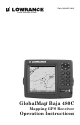
Pub. 988-0151-281 www.lowrance.
Copyright © 2005 Lowrance Electronics, Inc. All rights reserved. No part of this manual may be copied, reproduced, republished, transmitted or distributed for any purpose, without prior written consent of Lowrance Electronics. Any unauthorized commercial distribution of this manual is strictly prohibited. Lowrance is a registered trademark of Lowrance Electronics, Inc. MapCreate, FreedomMaps, and NauticPaths are trademarks of LEI. Fishing Hot Spots is a registered trademark of Fishing Hot Spots Inc.
Table of Contents Section 1: Read Me First!............................................................... 1 Capabilities and Specifications: GlobalMap Baja 480c................... 2 How Lowrance GPS Works ................................................................ 4 Introduction to GPS and WAAS......................................................... 6 How to use this manual: typographical conventions ........................ 8 Section 2: Installation & Accessories....................................
GPS Data files: .............................................................................. 53 Cancel Navigation ............................................................................ 56 Section 4: Advanced GPS Operations....................................... 57 Find Distance from Current Position to Another Location ............ 57 Icons .................................................................................................. 58 Routes.....................................................
Map Datum Selection ....................................................................... 82 Map Detail Category Selection ........................................................ 83 Map Orientation ............................................................................... 84 Navionics Charts............................................................................. 85 Port Information ........................................................................... 87 Tidal Current Information.........
WARNING! A CAREFUL NAVIGATOR NEVER RELIES ON ONLY ONE METHOD TO OBTAIN POSITION INFORMATION. CAUTION When showing navigation data to a position (waypoint), a GPS unit will show the shortest, most direct path to the waypoint. It provides navigation data to the waypoint regardless of obstructions.
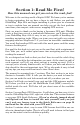
Section 1: Read Me First! How this manual can get you out on the road, fast! Welcome to the exciting world of digital GPS! We know you're anxious to begin navigating, but we have a favor to ask. Before you grab the GlobalMap Baja 480c and begin installing it, please give us a moment or two to explain how our manual can help you get the best performance from your compact, wide-screen, mapping GPS receiver. First, we want to thank you for buying a Lowrance GPS unit.
After you've learned the basics (or if you already have some GPS experience), you may want to try out some of the GlobalMap Baja 480c's many advanced navigation features. That brings us to Section 4, Advanced GPS Operations. This section contains the rest of the unit's GPS command functions, organized in alphabetical order.
Case size:......................... 5.4" H x 6.9" W x 3.4" D (13.8 x 17.6 x 8.6 cm); sealed and waterproof; suitable for saltwater use. MMC slots: ...................... One with waterproof door (SD card compatible). Recording:........................ MMC & SD memory cards for recording GPS trip details and displaying charts or custom maps. Back-up memory: .......... Built-in memory stores GPS data for decades. User settings are stored when unit is turned off. Languages:......................
Plot Trails: ...................... 10 savable; up to 9,999 points per trail. Zoom range:.................... 39 ranges; 0.02 to 4,000 miles. NOTE: The above memory capacities refer only to the GlobalMap Baja 480c's on-board memory. The amount of GPS data you can record and save for recall later is limited only by the number of MMC cards you have. NOTICE! The storage temperature range for your GlobalMap Baja 480c is from -4 degrees to +167 degrees Fahrenheit (-20 degrees to +75 degrees Celsius).
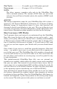
The performance doesn't stop there. Stored in the permanent memory of each unit is a basic background map of the entire world. We lock it in here at the factory — you can't change or erase this map. The background map is suitable for many navigation chores, but for maximum accuracy and much more detail, you need our optional mapmaking software, MapCreate 6. Some unit features — such as searching for businesses and addresses — won't work without a custom MapCreate map.
This unit automatically reads Custom Map Files directly from the MMC or SDC. To use a custom map, all you need to do is slide an MMC containing a map into the GlobalMap Baja 480c. Introduction to GPS and WAAS Well, now you know the basics of how the unit does its work. You might be ready to jump ahead to Section 2, Installation & Accessories, on page 11, so you can mount your GlobalMap Baja 480c and plug in the power. Or you might want to see how our text formatting makes the manual tutorials easy to skim.
A minimum of three satellites are required to determine a 2D fix. The system requires signal reception from three satellites in order to determine a position. This is called a 2D fix. It takes four satellites to determine both position and elevation (your height above sea level — also called altitude). This is called a 3D fix. Remember, the unit must have a clear view of the satellites in order to receive their signals. Unlike radio or television signals, GPS works at very high frequencies.
Non aviators can use WAAS signals to make their GPS navigation even more accurate. Your unit receives both GPS and WAAS signals. However, WAAS has some limits you should know about. First, the U.S. government has not completed construction of the WAAS system, so it is not yet fully operational. The ground stations are in place, but only a few of the needed WAAS satellites have been launched. WAAS can boost the accuracy of land GPS navigation, but the system is designed for aircraft.
Menu Commands A menu command or a menu option will appear in small capital letters, in a bold sans serif type like this: ROUTE PLANNING. These indicate that you are to select this command or option from a menu or take an action of some kind with the menu item. Text that you may need to enter or file names you need to select are show in italic type, such as trail name.
Notes 10
Section 2: Installation & Accessories Preparations You can install the GPS system in some other order if you prefer, but we recommend this installation sequence: Caution: You should read over this entire installation section before drilling any holes in your vehicle or vessel! 1. Determine the approximate location for the GPS unit, so you can plan how and where to route the cables for the antenna and power. This will help you make sure you have enough cable length for the desired configuration. 2.
You need to select an antenna installation location that has a clear, unobstructed view of the sky. After the module is installed, connect it to the end of the Y-adapter extension cable as shown in the following diagram. To connect it to the unit, insert the cable's splitter plug into the Network socket on the back of the unit and your system is ready to use. See the module's instruction sheet, publication part number 988-0147981, for complete installation directions.
Power Supply wires: red, black and white To unit NMEA-2000 Power wires: red, black and shield Data Cable wires: blue, yellow, orange and shield The Power/Data cable for this unit. Depending on your configuration, you may not use all of these wires. (For example, many units cannot operate an optional external speaker, so the white wire on the Power Supply cable isn't functional.) The following segments include instructions for installing all the wires that you will use with this unit.
with electrical interference. Therefore, it's safer to go ahead and attach the power cable directly to the battery. CAUTION: When using the unit in a saltwater environment, we strongly recommend that you shut off the power supply to the power cable when the unit is not in use. When the unit is turned off but still connected to a power supply, electrolysis can occur in the power cable plug.
To unit To power a NMEA-2000 buss, also connect NMEA-2000 Power cable to the boat's battery. Data Cable External speaker wire (not used by this unit) Red wire with 3 amp fuse Black wire Optional power off switch for saltwater installations 12 volt battery NMEA-2000 Power Cable Power connections for the GlobalMap Baja 480c GPS unit. NOTE: If you're powering a NMEA-2000 buss, you will attach both the NMEA-2000 Power cable and the unit's Power Supply cable to the boat's battery.
face on the GlobalMap Baja 480c and receive positioning information. The GlobalMap Baja 480c can exchange information with any device that transmits or receives NMEA 0183 data. See the following diagram for general wiring connections. Read your other product’s owner’s manual for more wiring information. NMEA Wiring (Data cable) To exchange NMEA 0183, the GlobalMap Baja 480c has one NMEA 0183 version 2.0 communication port. Com port one (Com-1) can be used to receive NMEA format GPS data.
ordering information is on the inside back cover of this manual. For a complete look at the many mounting options, visit the RAM web site at www.ram-mount.com. Optional R-A-M mounting system. Bracket Installation Mount the GlobalMap Baja 480c in any convenient location, provided there is clearance behind the unit when it's tilted for the best viewing angle. You should also make sure there is enough room behind the GlobalMap Baja 480c to attach the power and GPS antenna/receiver module cables.
Front Install the gimbal bracket. Orient the bracket so the arms slope toward the front of your unit. Drill a 1-inch (25.4 mm) hole in the dash for the power and antenna cables. The best location for this hole is immediately under the gimbal bracket location. This way, the bracket can be installed so that it covers the hole, holds the cables in position and results in a neat installation.
If you wish, you can fill in the hole around the cables with a good marine caulking compound. (Some marine dealers stock cable hole covers to conceal the opening.) No matter what type of installation you prefer, be sure to leave enough slack in the cables to allow tilting or swiveling the GlobalMap Baja 480c. If you choose to fill in the hole, be sure to position the cables against the rear edge of the hole as you apply the fill material.
Portable Installation Like many Lowrance products, the GlobalMap Baja 480c is capable of portable operation by using an optional portable power pack. The power pack and the magnet-equipped antenna module expand the uses for your GPS unit. The portable power pack makes it easy to transfer your unit from a boat to a car, recreational vehicle, airplane or other vehicle without drilling and mounting a second bracket.
MMC groove for card removal Thumb screw Insert card face up, this way Memory card compartment with a 16 MB MMC card installed. To remove an MMC 1. Open the card compartment door by unscrewing the thumb screw. The screw should only be finger tight. If it was over-tightened, use a thumbnail, a coin or a screwdriver to open the door. 2. Just press a finger against the label of the MMC and drag it from the slot. 3. Drag the MMC from the slot. To add an MMC or SD Card 1. Open the card compartment door. 2.
MapCreate™ 6 CD-ROM (left); MMC card reader for USB ports (right). Now that you have your GlobalMap Baja 480c installed, move on to Section 3, Basic GPS Operations. There, we'll present a series of stepby-step tutorials to teach you the basics of GPS navigation. Face Cover Your unit comes with a white protective cover that snaps on and off the front of the unit. This cover is intended for use when your unit and the vehicle it's mounted in are idle.
Section 3: Basic GPS Operations This section addresses the unit's most basic GPS operations. The tutorials presented in Sec. 3 follow a chronological order. Sec. 4, Advanced GPS Operations, will discuss other more advanced functions and utilities. Material in Sec. 4 is arranged in alphabetical order. Before you turn on the unit and find where you are, it's a good idea to learn about the different keys, the four Page screens and how they all work together.
Navigation Page and Map Page.) Each page represents one of the unit's major operation modes. 3. MENU – Press this key to show the menus and submenus, which allow you to select a command or adjust a feature. This also accesses search functions for streets, intersections, addresses and highway exits. 4. ARROW KEYS – These keys are used to navigate through the menus, make menu selections, move the map cursor and enter data. 5.
You can access the Main Menu from any of the three Page screens by pressing MENU|MENU. To clear the menu screen and return to the page display, press EXIT. Main Menu. The Main Menu commands and their functions are: Screen command: changes the contrast or brightness of the display screen. Sounds command: enables or disables the sounds for key strokes and alarms and sets the alarm style. Transparency command: adjust the level of transparency for menus.
Trip Calculator command: shows trip status and statistics. Timers command: controls the up timer, down timer and alarm clock settings. Browse MMC Files command: this allows you to view the installed MMC card and the files it contains. Pages The unit has three Pages that represent the three major operating modes. They are the Satellite Status Page, the Navigation Page and the Map Page. They are accessed by pressing the PAGES key, then using → or ← to select a Page. (Clear the Pages Menu by pressing EXIT.
Satellite Status Page. The unit has not locked on to any satellites and does not have a fix on its position (left). Satellite lock-on (right) with 3D position acquired (latitude, longitude and altitude), and WAAS reception. This screen shows a graphical view of the satellites that are in view. Each satellite is shown on the circular chart relative to your position. The point in the center of the chart is directly overhead.
The Satellite Status Page has its own menu, which is used for setting various options. (Options and setup are discussed in Sec. 5). To access the Satellite Status Page Menu, from the Status Page, press MENU. Navigation Page This screen has a compass rose that not only shows your direction of travel, but also the direction to a recalled waypoint. To get to the Navigation Page: Press PAGES|→ or ← to NAVIGATION|EXIT.
Speed (ground speed) is the velocity you are making over the ground. (If you wish, you can customize the Speed data box to display Closing Speed instead. Closing Speed is also known as velocity made good. It's the speed that you're making toward the waypoint. For instructions, see the Customize Page Displays entry in Sec. 5.) Track is the heading, or the current direction you are actually traveling. Bearing is the direction of a line-of-sight from your present position to the destination.
course. You need to steer left to return to the desired course. You can use the ZIN or ZOUT keys to change the cross track error range. A circular symbol depicting your destination (waypoint) appears on the screen as you approach the waypoint, as shown on the screen in the preceding figure. Travel Time is the time that it will take to reach your destination at your present closing speed. (You can also customize the time data box to show Arrival Time instead.
The Zoom In and Zoom Out keys zoom the map to enlarge or reduce its coverage area and the amount of mapping detail shown. There are 39 available map zoom ranges, from 0.02 miles to 4,000 miles. Map Page opening screen (left). Zoomed to 100 miles (center) and zoomed to 10 miles (right). Over Zoomed means you have reached the detail limits in an area covered only by the basic background map.
Background map vs. MapCreate map content The background map includes: low-detail maps of the whole world (containing cities, major lakes, major rivers, political boundaries); and medium-detail maps of the United States. The medium-detail U.S. maps contain: all incorporated cities; shaded metropolitan areas; county boundaries; shaded public lands (such as national forests and parks); some major city streets; Interstate, U.S.
Interstate Major Street Cursor line Minor Streets POI Pop-up POI Marker Restaurant POI School POI Position, distance and bearing data Zoom Range When the map is zoomed out far enough, most POIs appear as square dots (left). As you zoom in closer, the symbols become readable icons. In the 0.2 mile zoom example (right), the cursor has selected the Cupps Café POI, which triggers a pop-up box with the POI name. This pop-up box works on POIs at any zoom range.
Digital Data map page (left); Two Position Formats page (right). Resize Window command In pages that have two major windows (such as two maps) you can toggle back and forth between the two windows by pressing PAGES|PAGES. This allows you to change which map your cursor moves on, and which map the menu operates on. A black title bar denotes the active window. Pages Menu with Two Map option selected (left). Map Page with two map windows (right). The left map is active.
the window widths. Press an arrow key parallel to the centerline to switch between horizontal and vertical layout. (You can only change size, not switch layout, on the Map With Sonar page - it's always two vertical windows.) Press EXIT to clear the four flashing arrows. Fig. 1 Fig. 2 Fig. 3 After selecting Resize Window command (from left to right): Fig. 1. Two Maps page display with four flashing arrows on the dividing centerline. Fig. 2.
Basic GPS Quick Reference Start outdoors, with a clear view of the open sky. As you practice, try navigating to a location at least a few blocks away. While you're learning, navigation in too small an area will constantly trigger arrival alarms. 1. Connect the unit to electric power and the antenna module. Make sure the MMC is in. (See complete installation details beginning on page 11.) 2. To turn on the unit, press and release PWR key. 3.
Find Your Current Position Finding your current position is as simple as turning the unit on. Under clear sky conditions, the unit automatically searches for satellites and calculates its position in approximately one minute or less. NOTE: "Clear sky" means open sky, unobstructed by terrain, dense foliage or structures. Clouds do not restrict GPS signal reception. If for some reason satellite acquisition takes longer, you may be inside a structure or vehicle or in terrain that is blocking signal reception.
Cursor line Cursor line Selected airport POI pop-up data box Distance measured by cursor The selected airport to the northwest is 4.2 miles away. Selecting Any Map Item with the Cursor 1. Use the zoom keys and the arrow keys to move around the map and find the item you wish to select. 2. Use the arrow keys and center the cursor cross-hair on the desired object. On most items, a pop-up box will give the name of the selected item.
After the unit has acquired a position: 1. Press WPT|↓ to POI-RESTAURANTS. 2. You could search the entire restaurant category, but in this example we will narrow our search. Press → to SUBCATEGORY column|↓ to FAST FOOD CHAINS|ENT|↓ to NEAREST|ENT. 3. The unit says it is calculating, then a list of restaurants appears, with the closest at the top of the list, and the farthest at the bottom of the list. The nearest is highlighted.
POI information screen on fast food restaurant nearest this position. Screen shows name, street address, phone number, latitude/longitude, distance to restaurant and its compass bearing. Go To Waypoint command (left); Find On Map command (right). 6. The unit's map appears, with the cross-hair cursor highlighting the restaurant' s POI symbol. A pop-up data box shows the POI's name, distance and bearing. A data box at the bottom of the screen continues to display the location's latitude and longitude.
NOTE: Search works from mapping and POI data loaded in the unit. If you do not have a high-detailed custom map (containing POI data) for the area you are searching loaded on the MMC, you may not find anything. Set a Waypoint A waypoint is simply an electronic "address," based on the latitude and longitude of a position on the earth. A waypoint represents a location, spot or destination that can be stored in memory, then be recalled and used later on for navigation purposes.
Create Waypoint at Current Position While you are traveling, press WPT|WPT. The waypoint is saved and automatically given a name with a sequential number, such as "waypoint 003." The waypoint symbol and number appear on the map. Step 1. Step 2. Step 3. Step 4. Sequence for setting a waypoint. Step 1: while traveling, quickly press WPT twice to call up Find Waypoint screen (seen in Step 2) and set a point. Step 3: a message says the waypoint has been saved.
To revert back to the default symbol, edit a waypoint and choose the original symbol, or use the Reset Options command (described in Sec. 5). Create Waypoint on Map 1. Use the arrow keys to move the cursor to the place where you want to make a waypoint. 2. Press WPT|WPT. The waypoint is saved and automatically given a name with a sequential number, such as "waypoint 001." The waypoint symbol and number appear on the map. Create Waypoint by Entering a Position 1.
Waypoint Course line (dotted) Trail line (solid) Destination name Off course range, set at 0.20 mile Navigation Page, navigating toward waypoint 004 and leaving a trail. Set Man Overboard (MOB) Waypoint One of boating's most terrifying events is having a friend or family member fall overboard. This situation can be deadly on any body of water — fresh or salt. It's particularly dangerous at night or if you're out of sight of land.
Navigating to Man Overboard: Man Overboard Activated message (left), Navigation Page (center); Map Page (right). The victim is to the starboard of the vessel. The GPS shows where to go for the rescue. The man overboard position is also stored in the waypoint list for future reference. It can be edited the same as any other waypoint. This prevents the inadvertent loss of the current Man Overboard position. To cancel navigation to MOB, press MENU|MENU|↓ to CANCEL NAVIGAto YES|ENT.
Navigate to cursor. In this example, the cursor has selected the town of Oologah, Oklahoma. 3. Press MENU|ENT and the unit will begin navigating to the cursor location. The Map Page will display a dotted line from your current position to the cursor position. The Navigation Page displays a compass rose showing navigation information to your destination. See the following examples. The 15-mile zoom (left) clearly shows the dotted course line connecting your current position to your destination.
Navigate to a Point of Interest For POIs that are in view on the map, you can easily use the Navigate to Cursor command above; just use the cursor to select the POI. The other method involves searching for POIs with the Find Waypoint command, launched with the WPT key. (See the searching example earlier in this section, or turn to Sec. 6, Searching, for detailed instructions on POI searches.
Visible symbol Active symbol Sequence for saving a trail and beginning a new one (after My Trails command is selected). The Trails Menu (left). The arrow to the right of Trail 14 indicates the trail is "active," and the check to the left indicates the trail is visible on the map display. The Edit Trail menu (right) with the Active command selected. To Save a Trail 1. Press MENU|MENU|↓ to MY TRAILS|ENT. 2. Press ↓ to the Active Trail Name|ENT. 3. Press ↓ to ACTIVE|ENT. This unchecks the Active option. 4.
New trail, named "Trail 15," is created when Trail 14 is made inactive. Any new travel will be recorded in this trail, which is active and visible. Trails do not need to be visible in order to be active. You can save and recall up to 10 different plot trails, which can also be copied to your MMC for archiving or for transfer to your MapCreate software. Tip: Another quick way to stop recording one trail and begin a new one is to use the New Trail command: Press MENU|MENU|↓ to MY TRAILS|ENT|ENT.
3. Press ↓ to ACTIVE|→ to VISIBLE|ENT. To return to the previous page, press EXIT|EXIT|EXIT|EXIT. To turn on trail display: 1. Press MENU|MENU|↓ to MY TRAILS|ENT. 2. Press ↓|↓ to enter the Saved Trail list, then use ↑ or ↓ to select the desired Trail Name|ENT. 3. Press ↓ to ACTIVE|→ to VISIBLE|ENT. To return to the previous page, press EXIT|EXIT|EXIT|EXIT. Navigating Trails There are three methods for following a trail: visual trailing, navigating a trail (forward) and backtracking a trail (backward).
3. Press → to DELETE TRAIL|↓ to NAVIGATE|ENT. 4. Press ↓ to NAVIGATE|ENT. The unit begins showing navigation information along the trail. NOTE: If you are already located at or near the beginning of your trail, the arrival alarm will go off as soon as you hit Enter. Just press EXIT to clear the alarm and proceed. 5. Now, begin moving and follow your unit. 6. When you reach your destination, be sure to cancel your navigation: press MENU|MENU|↓ to CANCEL NAVIGATION|ENT.
On the Map Page, the trail you are navigating is represented by a dotted line that alternates with a flashing solid line. The Navigation Page will also show the navigated trail as a dotted line. The bearing arrow on the compass rose points to the next waypoint on the trail. As you travel, the arrival alarm will go off when you near a trail waypoint, and the bearing arrow on the compass rose will swing around and point to the next trail waypoint. Press EXIT to clear the alarm.
3. Press → to DELETE TRAIL|↓ to NAVIGATE|ENT. 4. Press ↓ to NAVIGATE|→ to REVERSE|ENT|← to NAVIGATE|ENT. The unit begins showing navigation information along the trail, in reverse. NOTE: If you are already located at or near the end of your trail, the arrival alarm will go off as soon as you hit ENTER. Just press EXIT to clear the alarm and proceed. 5. Now, begin moving and follow your unit. 6. When you reach your destination, be sure to cancel your navigation: press MENU|MENU|↓ to CANCEL NAVIGATION|ENT.
The Transfer My Data submenu asks if you want to save data to the MMC or load data from the MMC into the unit's memory. 2. The Transfer My Data menu includes a message which tells you if an MMC is present or not. If no MMC is present, you must first insert a card into the unit in order to activate the Load or Save commands. To transfer data from the unit to the MMC: press ENT (for SAVE.) To transfer data from the MMC to the unit: press → to LOAD|ENT. 3.
These figures (from left to right) show the menu sequence for naming and saving a GPS Data File from the unit's memory to an MMC. 4. Loading to unit memory: There may be more than one GPS Data File (*.USR) on the card. To select a file, press ENT to activate the selection box, use ↓ or ↑ to highlight the file, then press ENT to accept the selection. Next, press ↓ to LOAD DATA|ENT. The unit will display a completion message when the data transfer is finished.
Figure 1. Figure 2. Figure 4. Figure 3. These figures show the menu sequence for loading a GPS Data File from an MMC into the unit's memory. Cancel Navigation You can turn off any of the navigation commands after you reach your destination or at any other time by using the Cancel Navigation command. Press MENU|MENU|↓ to CANCEL NAVIGATION|ENT|← to YES|ENT.
Section 4: Advanced GPS Operations Find Distance from Current Position to Another Location 1. While on the Map Page press: MENU|↓ to FIND DISTANCE|ENT. 2. Center your cursor over the position you want to find the distance to. A rubber band line appears, connecting your current position to the cursor's location. The distance along that line will appear in a pop-up box. The box also shows the bearing to the point you're measuring to. 3. Press EXIT to return to regular operation.
Icons Icons are graphic symbols used to mark some location, personal point of interest or event. They can be placed on the map screen, saved and recalled later for navigation purposes. These are sometimes referred to as event marker icons. This unit has 42 different symbols you can pick from when creating an icon. Icons are similar to waypoints, but they do not store as much information (like names) as waypoints do. You can't use a menu to navigate to icons as you can with waypoints.
1. Press MENU|↓ to DELETE MY ICONS|ENT. 2. Press ↓ to DELETE ALL ICONS, DELETE BY SYMBOL, or DELETE FROM MAP and press ENT. Delete icons menu. The Delete All Icons command will ask if you are sure. Press ← to YES|ENT. All icons will be deleted from the map. The Delete by Symbol command will launch the Select Symbol menu. Press ← or ↑ or → or ↓ to select the icon symbol to delete, then press ENT. A message appears saying all icons with the selected symbol have been deleted.
The course from one waypoint to the next is a leg; routes are composed of one or more legs. The legs of all GPS routes are based on straight lines between waypoints. A route provides the automatic capability to navigate through several waypoints without having to reprogram the unit after arriving at each waypoint.
Selecting the Route Planning command on Main Menu will open the Route List screen. 2. Press ↓ to (END OF ROUTE)|ENT|↓ to ADD FROM MAP|ENT. The Map Page appears with the cursor showing. Edit Route menu (left). Edit Route Waypoints menu (right), with Add from Map command selected. 3. Use the Zoom keys and arrow keys to move the map and cursor until the cursor is centered on the spot where you want your route to begin.
1. 2. 3. Route creation sequence (from left to right): Fig. 1. Set route waypoint (1) at 11th St. & 145th Ave. Fig. 2. Zoom in; move cursor north to set point (2) at 145th & Admiral. Fig. 3. With point (2) set, move cursor east to mark interstate on-ramp with waypoint (3). In figures 2 and 3, notice the rubber band line extending from the previously set waypoint to the cursor. This line will become the course for the route. 4. 5. 6. Route creation sequence, continued: Fig. 4.
You can edit the route and run other commands, but if you are finished with the route for now, return to the last page displayed by pressing EXIT|EXIT|EXIT|EXIT|EXIT. Delete a Route 1. From the NAVIGATION PAGE, press MENU|ENT or from the MAP PAGE press MENU|MENU|↓ to ROUTE PLANNING|ENT. 2. Press ↓ to route name|ENT. 3. Press ↓ to NAVIGATE|ENT|→ to DELETE|ENT|← to YES|ENT. Tip: You can also delete all routes at once: 1.
Edit Route Waypoints menu. 3. Use ↓ and ↑ to select a command from the Edit Route Waypoints menu and press ENT. Add From Map lets you insert a waypoint in the route by clicking on a map location with the cursor. Add Waypoint calls up the Waypoint List so you can insert a waypoint from the list. Remove Waypoint will delete the waypoint from the route. View Waypoint will show you where the selected waypoint is on the map.
Selecting the Route Planning command on Main Menu brings up the Routes menu (left). Edit Route menu (right). Navigate command is selected in the Action box. 2. Press ↓ to select route name|ENT|↓ to NAVIGATE|ENT. 3. Upon arrival at your destination, cancel navigation: press MENU|MENU|↓ to CANCEL NAVIGATION|ENT|← to YES|ENT. The following figures show what the Navigation Page and Map Page look like while navigating a route.
Figure 1. Figure 2. Figure 3. Figure 4. Navigating along a route: Fig. 1 shows the Navigation Page at the start of a route, heading straight for the first waypoint (Wpt 1). In Fig. 2, the traveler has arrived at Wpt 1; the arrival alarm has been triggered and the bearing arrow on the compass rose has turned to point toward Wpt 2, off to the east. In Fig. 3 the traveler has turned east on his new course and is heading straight for Wpt 2, which is 2.37 miles away. Fig.
Tip: You can also delete all trails at once: 1. Press MENU|MENU|↓ to MY TRAILS|ENT. 2. Press → to DELETE ALL|ENT|← to YES|ENT. Edit a Trail Name To edit a trail name: press MENU|MENU|↓ to MY TRAILS|ENT|↓ to trail name|ENT|ENT. Press ↑ or ↓ to change the first character, then press → to the next character and repeat until the name is correct. Press ENT then EXIT|EXIT|EXIT|EXIT to return to the previous page display.
Edit Trail Menu with Pattern option selected (left). Edited trail with dotted line pattern (right). Utilities Utilities are useful tools for traveling or for outdoor activities. Alarm Clock To get to the alarm clock menu: press MENU|MENU|↓ to TIMERS|ENT|↓ to ALARM CLOCK|ENT. Sun/Moon Rise & Set Calculator To get to the Sun/Moon menu: press MENU|MENU|↓ to SUN/MOON CALCULATIONS|ENT. Trip Calculator To get to the Calculator menu: press MENU|MENU|↓ to TRIP CALCULATOR|ENT.
To delete all waypoints at one time: press MENU|MENU|↓ to SYSTEM SETUP|ENT|↓ to DELETE ALL MY WAYPOINTS|ENT|← to YES|ENT. To return to the previous page, press EXIT|EXIT. Edit a Waypoint Waypoint Name To edit waypoint name: 1. Press WPT|ENT|ENT|ENT|↓ to waypoint name|ENT|↓ to EDIT WAYPOINT|ENT|ENT. 2. Press ↑ or ↓ to change the first character, then press → to the next character and repeat until the name is correct. Press ENT then EXIT|EXIT|EXIT|EXIT to return to the previous page display.
1. Press WPT|→ to SUBCATEGORY column|↓ to NEW|ENT. 2. Press ↓ or ↑ to AVERAGE POSITION|ENT|press → to CREATE|ENT. 3. Wait while the unit takes points to average for the position. (The greater the number of points, the greater the accuracy.) When the desired number of points accumulates, press ENT to create and save the waypoint. 4. The Edit Waypoint menu appears. You can simply save the waypoint by pressing EXIT|EXIT or you can edit the waypoint.
Section 5: System & GPS Setup Options Alarms This unit has several GPS alarms. The factory default setting has all of these but the anchor alarm turned on. You can turn the alarms off and on and change their distance settings. You can set an arrival alarm to flash a warning message and sound a tone when you cross a preset distance from a waypoint. For example, if you have the arrival alarm set to .1 mile, then the alarm will flash a message when you come within .1 mile of the recalled waypoint.
3. To change distance settings, scroll ↓ or ↑ to select the desired category, then press →|ENT to activate the distance dialog box. Press ↑ or ↓ to change the first character, then press → to the next character and repeat until the name is correct. 4. When your adjustments are finished, return to the last page displayed by repeatedly pressing EXIT. IMPORTANT ALARM NOTES: Anchor Alarm - The anchor alarm may be triggered even when you're sitting still. This typically happens when using small (less than .
Check MMC Files and Storage Space To check MMC Files: Press MENU|MENU|↓ to BROWSE MMC FILES|ENT. Main Menu (left). MMC File Browser (right). Communications Port Configuration The unit has one NMEA 0183 version 2.0 compatible communication port, or com port for short. The Com Port Menu, which is accessed from the System Setup Menu, allows you to configure the communications port to send or receive data to another electronic device, such as an autopilot. The com port can be used for NMEA data transfer.
To set Com Port Configuration: 1. Press MENU|MENU|↓ to SYSTEM SETUP|ENT. 2. Press ↓ to COMMUNICATIONS PORT|ENT. Configure NMEA You can configure the unit to use specific NMEA sentences. 1. Press MENU|MENU|↓ to SYSTEM SETUP|ENT. 2. Press ↓ to COMMUNICATIONS PORT|ENT|↓ to CONFIGURE NMEA|ENT. 3. A menu appears showing the prefixes of the available NMEA sentences. A check mark next to a prefix means the prefix is in use. Use ↑ ↓ → ← to select a prefix, then press ENT to turn off the prefix.
(Standard + 10); Map Fix; Loran TD; British, Irish, Finnish, German, New Zealand, Swedish, Swiss, Taiwan and Greek. UTM's are marked on USGS topographic charts. This system divides the Earth into 60 zones, each 6 degrees wide in longitude. British, Irish, Finnish, German, New Zealand, Swedish, Swiss, Taiwan, and Greek grid systems are the national coordinate system used only in their respective countries. In order to use these grid systems, you must be in the respective country.
Configure Loran TD menu. Map Fix Map Fix is used with charts or maps. This system asks for a reference position in latitude/longitude, which you take from a marked location on the map. It then shows the present position as distance on the map from that reference point. For example, if it shows a distance of UP 4.00" and LEFT 0.50", you then measure up four inches and to the left a half-inch from the reference point on the map to find your location.
The screen below appears, and MAP SCALE is highlighted. Press ENT and enter the map's scale. This is generally at the bottom of the paper map. It's shown as a ratio, for example 1:24000. Press EXIT and the unit returns to the Configure Map Fix screen. Configure a map fix so the unit can find your position on a printed chart or topographical map. Press → to SELECT ORIGIN|ENT|ENT|ENT to bring up the waypoint list. Select the waypoint that you saved the reference point under and press ENT.
change the box or hit ↑, ↓, → or ← to select another box, then press ENT. You'll see a list of categories with "+" or "–" symbols next to each category. A category with a "+" is expandable, meaning its contents are currently hidden. Customize Menu, with "GPS Data" and "Navigation" categories expanded. Selecting the category name and pressing ENT will show the category's contents, so you can choose items within it.
You can steer your position and change speed on the map by using the arrow keys (STEER WITH ARROWS command) or by setting the track and speed in the dialog boxes provided on the simulator menu screen. To get to the GPS Simulator: 1. Press MENU|MENU|↓ to GPS SETUP|ENT. 2. Press ↓ to GPS SIMULATOR|ENT. The GPS Simulator Menu appears. GPS Simulator menu. Make the desired settings, then turn the simulator on by highlighting the GPS SIMULATOR ON box and pressing ENT key.
2. Set SPEED to zero. Select STEER WITH ARROWS command and press ENT, which turns on the simulator and returns you to the Map Page. 3. Begin navigating along the trail/route. (If you are close enough to the first waypoint, the arrival alarm will usually go off as soon as navigation begins. Press EXIT to clear the alarm.) When navigation starts, press ↑ to increase speed to the desired setting. 4. Press EXIT to turn off the steering and speed boxes.
To turn this feature on, from the MAP PAGE, press MENU|↓ to AUTO ZOOM|ENT|EXIT. Repeat these steps to turn it off. Map Data This menu lets you turn the map off, if desired (which turns the map screen into a GPS plotter); turn off or on the pop-up map info boxes; draw the map boundaries or boxes around the areas of high detail; or show water on the map as white to contrast land. You can also turn on or off Map Overlays, which display latitude and longitude grid lines or range rings on the map.
Map Boundaries From the Map Page, press MENU|↓ to MAP DATA|ENT. Press ↓ to DRAW MAP BOUNDARIES. With the option highlighted, press ENT to check it (turn on) and uncheck it (turn off.) After the option is set, press EXIT|EXIT to return to the page display. Fill Water With White From the Map Page, press MENU|↓ to MAP DATA|ENT. Press ↓ to FILL WATER WITH WHITE. With the option highlighted, press ENT to check it (turn on) and uncheck it (turn off.
All datums are named. The GPS system is based on the WGS-84 datum, which covers the entire world. Other datums may also cover the entire world, or just a small portion of it. By default, your position shows using the WGS-84 datum. However, it can show your position using one of 191 different datums. Different datums can be selected; to change the datum: 1. Press MENU|MENU|↓ to GPS SETUP|ENT|↓ to DATUM SELECTION|ENT. 2. Scroll ↓ or ↑ to select the desired datum, then press ENT. 3.
Map Categories Drawn Menu. Map Orientation By default, this receiver shows the map with north always at the top of the screen. This is the way most maps and charts are printed on paper. In Track Up mode, map shows "N" and arrow to indicate north. Map orientation is shown in north up (left) and track up (right). This is fine if you're always traveling due north. What you see to your left corresponds to the left side of the map, to your right is shown on the right side of the map, and so on.
To correct this problem, a track-up mode rotates the map as you turn. Thus, what you see on the left side of the screen should always be to your left, and so on. Another option is course-up mode, which keeps the map at the same orientation as the initial bearing to the waypoint. When either the track-up or course-up mode is on, an "N" shows on the map screen to help you see which direction is north. To change map orientation: from the Map Page, press MENU|↓ to MAP ORIENTATION|ENT.
Entrance to Chesapeake Bay (left) in a MapCreate 6 custom map, 10-mile zoom. Same position on Navionics chart at 11-mile zoom (center) and 5-mile zoom (right). To display a Navionics chart: 1. Install the Navionics MMC in the memory card compartment and turn on the unit. (For full card install instructions, see Sec. 2.) WARNING: You should never format the MMC containing your Navionics chart. Formatting the MMC will permanently erase the chart from the card. 2.
Port Information Navionics charts contain Port Services information, represented by anchor icons on the map display. An example is displayed in the following figure. To view Port Services information: 1. Use the arrow keys to move the cursor over a Port Services icon. When selected, a pop-up name box appears. 2. Press WPT to display the Port Services Information screen. The Port Services information screen has two windows. The top window lists the various service categories.
Port Services information screens. Tidal Current Information Navionics charts contain Tidal Current information, represented at large zoom ranges by a box icon with the letter "C." The icon stands for a Tidal Current Station location. An example is displayed at right. When you zoom in to a sufficiently small zoom range, the icon itself becomes an animated arrow showing tidal current velocity and direction for the selected tidal station at the present time.
Tidal Current Station icon in animated mode Pop-up name box Cursor lines Navionics chart showing Tidal Current Station icon selected by cursor. In this example, the tidal current is in flood but it's about to enter the slack water stage. The current is flowing to the west at 0.1 mph. Current Information screen. The Tidal Current Information screen displays daily tidal current data for this station on this date at the present time.
You can look up tidal current data for other dates by changing the month, day and year selection boxes. To select another date: 1. Use → and ← to highlight month, day or year, then press ENT. 2. Use ↑ and ↓ to select the desired month, day or year, then press ENT. To clear the information screen, press EXIT. Tide Information Navionics charts contain Tidal Information, represented at large zoom ranges by a box icon with the letter "T." The icon stands for a Tidal Station location.
Tide Information screen. The Tide Information screen displays daily tidal data for this station on this date at the present time. The graph at the top of the screen is an approximate view of the tidal range pattern for the day, from midnight (MN), to noon (NN) to midnight (MN). The dotted line across the graph is the Mean Lower Low Water line (MLLW). The height scale on the top right side of the graph changes, based upon the maximum range of the tide for that day.
Overlay Data, with "Navigation," "Trip Calculator" and "Time" categories expanded. To overlay information on your screen: 1. While on the Navigation Page or a Map Page, press MENU| OVERLAY DATA|ENT. to 2. You'll see a list of the overlay data currently shown, if any. Select TO ADD) and press ENT. The data viewer shows information categories with "+" or "–" symbols next to each category name. A category with a "+" next to it is expandable, meaning its contents are currently hidden.
From Overlay Data Shown (left) press ENT to see Data Viewer (center). Select a category and press ENT; then select information to float on screen and press ENT (right). To remove overlaid data: 1. While on the Page that shows the item or items you want to remove, press MENU|↓ to OVERLAY DATA|ENT. 2. You'll see a list of the overlay data currently displayed. Select the item you want to remove from your display and press ENT|ENT to remove the data. To remove another item, select the item and press ENT|ENT.
1. From one of the Map Pages, press MENU|↓ to OVERLAY DATA|ENT. 2. You'll see a list of the overlay data currently displayed. Select the item you want to move and press ENT|→|ENT. 3. The data begins to flash on your screen. Use any combination of →, ←, ↑ and ↓ to move the data to a new location on the screen. 4. When satisfied, press EXIT| EXIT. To change displayed data font size: 1. From the Map or Sonar page, press MENU|↓ to OVERLAY DATA|ENT. 2.
System Setup menu (left) with Pop-up Help highlighted. Pop-up Help message for Go To Cursor (right), located on the Map Menu. Reset Options To reset all features to their factory defaults: 1. Press MENU|MENU|↓ to SYSTEM SETUP|ENT|↓ to RESET OPTIONS|ENT|← to YES|ENT. NOTE: Reset Options does not erase any waypoints, routes, icons or plot trails. Reset Options command (left) and the Reset Options Menu (right). Screen Contrast and Brightness To access the Screen menu, press MENU|MENU|ENT.
Screen Command (left) and Screen Menu (right). To adjust the display's brightness: Press ↓ to BRIGHTNESS. Press → or ← to move the bar. The left end of the scale is minimum contrast; the right end is maximum contrast. To adjust the screen's display mode: Press ↓ to DISPLAY MODE|ENT|press ↑ or ↓ to select mode|EXIT. Display Mode menu. Set Language This unit's menus are available in 10 languages: English, French, German, Spanish, Italian, Danish, Swedish, Russian, Dutch and Finnish.
3. Use ↓ or ↑ to select a different language and press ENT. All menus now appear in the language you selected. Set Local Time Using the correct local time setting is handy when estimating local arrival time while navigating. Also, the time and date are saved when a waypoint is created. To access the Set Local Time menu, you must first acquire your position. Once that is done: press MENU|MENU|↓ to SYSTEM SETUP|ENT|↓ to SET LOCAL TIME|ENT. Once in the Time Settings menu: To set Local Time: Press ENT.
If you want, you have the option of turning off the WAAS Acquired/Lost alarm without affecting how the unit uses WAAS. Here's how: 1. Press MENU|MENU|↓ to GPS SETUP|ENT|↓ to SHOW WAAS ALARM. 2. With the option highlighted, press ENT to uncheck it (turn off) and check it (turn on.) After the option is set, press EXIT|EXIT to return to the page display. 3. You can return to this command and press ENT again to turn the feature on.
Sounds command (left); The Sounds menu (right). Once in the Sounds menu: To set Key Press Sounds: With the option highlighted, press ENT to check it (turn on) and uncheck it (turn off.) After the option is set, press EXIT|EXIT to return to the page display. To set Alarm Sounds: Press ↓ to ALARM SOUNDS. With the option highlighted, press ENT to check it (turn on) and uncheck it (turn off.) After the option is set, press EXIT|EXIT to return to the page display. To set Alarm Volume: Press ↓ to VOLUME.
Track Smoothing option, turned on. Trail Options There are several options you can use with trails. Some affect all trails, other options can be applied to a particular trail. You can change the way trails are updated, display or hide trails, create a new trail, delete a trail, etc. General Trail Options To access the Trails Menu: 1. Press MENU|MENU|↓ to MY TRAILS|ENT. Main Menu (left); Trails Menu (center); Trail Options (right).
WARNING: If you uncheck the Update Trail option, automatic trail creation and recording will be turned off. You must turn it back on to record trails. The default setting is on. From the Trails Menu, press → to TRAIL OPTIONS|ENT. With UPDATE ACTIVE TRAIL highlighted, press ENT to check it (turn on) and uncheck it (turn off.) Update Trail Criteria (Auto, Time, Distance) The options are automatic, time, or distance.
Specific Trail Options Delete Trail To delete a specific trail: From the Trails Menu, press ↓ to Trail Name|ENT. The Edit Trail menu appears as seen in the following figure. Press → to DELETE TRAIL|ENT|← to YES|ENT. Edit Trail menu. New Trail To manually start a new trail, in the Trails Menu, make sure NEW TRAIL is highlighted and press ENT.
Main Menu with Transparency command selected To adjust Menu Transparency level: Press MENU|MENU| to TRANSPARENCY|ENT. The TRANSPARENCY slider bar appears. Press or to move the bar. The lower end of the scale makes the menus opaque; the upper end is maximum transparency. Units of Measure This menu sets the speed and distance (statute or nautical miles, meters), depth (feet, fathoms, or meters), temperature (degrees Fahrenheit or Celsius) and heading (true or magnetic) units.
Notes 104
Section 6: Searching NOTE: The background map loaded in your unit lets you to search for U.S. Interstate Highway exits and exit services, as well as some land features, including cities and lakes. For a full set of searchable land features, including landmarks, streets, addresses and Points of Interest, you must load your own high-detail custom map produced with our MapCreate 6 software. For a complete description of what detail is found in the background map and custom MapCreate maps, see page 31.
3. To enter an address number, press ↑ or ↓ to change the first number, then press → to move the cursor to the next number and repeat until the number is correct, then press ENT. Find Address Menu. 4. To enter a street name, press ↓ to STREET|ENT. There are two options: A. You can spell out the name in the top selection box. Press ↑ or ↓ to change the first letter, then press → to move the cursor to the next letter and repeat until the name is correct, then press ENT|ENT. B.
If you select yes, there are two options: A. You can spell out the city name in the top selection box. Press ↑ or ↓ to change the first letter, then press → to move the cursor to the next letter and repeat until the name is correct, then press ENT|ENT. B. Jump down to the lower selection list by pressing ENT, then press ↓ or ↑ to select a city name from the list, then press ENT. The city name you selected is now in the city field.
Address search result list (left). Map Page showing location of the address on the map (center), highlighted by cursor. After the address is located (right), you can navigate to it ("D" symbol for destination). 8. To navigate to the address, press MENU|ENT|EXIT and the unit will begin showing navigation information to the address pointed out by the cursor. If you are only looking up an address (not navigating), just press EXIT to return to the previous page.
A POI selected by the cursor (left), POI information screen (right). NOTE: Since the Go To Waypoint command is highlighted, you can navigate to the selected POI by pressing ENT|EXIT while in the POI Waypoint Information screen. Find Interstate Highway Exits 1. From the Map Page, press MENU|↓ to HIGHWAY EXITS|ENT, which calls up the Find Exit menu. Find Highway Exits command (left) and Find Exit menu (right). 2. First, select a highway name by pressing ENT, which calls up the Find By Name menu.
Find By Name menu. 3. Once you have selected a highway name you can then select an exit. Press ↓ to switch to the Exit List, then press ↓ or ↑ until you highlight the exit, then press ENT. Find Exit menu, with an exit selected in the Exit List. 4. In the Exit Information screen you have two choices. A. Press ENT to navigate or "go to" the exit. B. Press →|ENT to find the exit on the map.
"Go To Exit" option (left), "Find On Map" option (right). Tip: You can also look up some additional information on the Exit Services located near this exit. Press ↓ to SERVICES|press ↓ or ↑ to select Service Name|ENT. Exit Information (left); general location and amenities (right). Find Map Places or Points of Interest (POI) 1. Press WPT, press ↓ or ↑ to select a map place or POI category, then press ENT. (To narrow your search, press → then press ↓ or ↑ to select a subcategory before pressing ENT.
Find Waypoint menu with Lodging POI category selected (left), and with the RV Parks subcategory selected (right). 2. Search by nearest POI. Press ↓|ENT. The "find by nearest" menu will show a "calculating" screen, then a list of the nearest POI's will appear. Press ↓ or ↑ to the selected POI and press ENT to call up the POI's Waypoint Information screen. Find Nearest option (left); Calculating screen (center); POI list (right). 3. Search by name of POI. Press ENT. There are two options: A.
Find by Name option (left), Find by Name menu (right). 4. When the POI's Waypoint Information screen is displayed, you can choose to "Go To" the POI waypoint by pressing ENT or find it on the map by pressing ↓|ENT. "Go To" POI option (left); "Find on Map" POI option (right). Find Streets or Intersections Find a Street 1. From the Map Page, press MENU|↓ to FIND STREETS|ENT and the Find Streets Menu appears.
Find Streets command (left); Find Streets menu (right). 2. You must first fill in a street name in the First Street dialog box. Press ENT to display the Find By Name menu. There are two options: A. You can spell out the street in the top selection box. Press ↑ or ↓ to change the first letter, then press → to move the cursor to the next letter and repeat until the name is correct, then press ENT|ENT. B. Or you can jump down to the lower box and pick a street from the selection list.
A message appears asking you to wait while the unit finds the street. When the Streets Found list appears, press ↑ or ↓ to select the street you are searching for and press ENT. The Find Streets menu with the Find First Street command highlighted (left). The Streets Found list (right). 4. The Map Page appears, with the cursor pointing to the found street. Map Page showing results of a street search. The cursor points to the located street.
1. From the Map Page, press MENU|↓ to FIND STREETS|ENT and the Find Streets Menu appears. 2. You must fill in a street name in the First Street dialog box. Press ENT to display the Find By Name menu. There are two options: A. You can spell out the street in the top selection box. Press ↑ or ↓ to change the first letter, then press → to move the cursor to the next letter and repeat until the name is correct, then press ENT|ENT. B.
(In our example, we selected the intersection of SW 80th Street and SW 71st Avenue in Miami, Fla.) 7. The Map Page appears, with the cursor pointing to the found intersection. The intersection in our example is shown in the following figure. Map Page showing results of an intersection search. The cursor points to the located intersection. If you want to navigate to the found intersection, just press MENU|ENT|EXIT. Find Waypoints 1. Press WPT|ENT. 2. If searching for the waypoint By Name, press ENT.
3. If you're looking for nearest, the unit says it is calculating, then a list of waypoints appears. The closest is highlighted at the top of the list and the farthest at the bottom of the list. Calculating message (left) and list of the nearest waypoints (right). 4. To see location information on the closest (highlighted) waypoint, press ENT and the Waypoint Information screen appears. (If you wanted to, you could select another waypoint from the list with the ↑ or ↓ keys.) A.
To clear these menus and return to the previous page, press EXIT repeatedly. 5. If you're looking by name, there are two options: A. You can spell out the name in the top selection box. Press ↑ or ↓ to change the first letter, then press → to move the cursor to the next letter and repeat until the name is correct, then press ENT|ENT. B. Or you can jump down to the lower selection list by pressing ENT, then press ↓ or ↑ to select a waypoint from the list, then press ENT.
Notes 120
Section 7: Supplemental Material Datums Used by This Unit WGS 1984 Default Zaire, Zambia and Zimbabwe Adindan Mean for Ethiopia, Sudan Arc 1950 - Botswana Adindan Burkina Faso Arc 1950 - Lesotho Arc 1950 - Burundi Arc 1950 - Malawi Adindan Cameroon Adindan Ethiopia Arc 1950 - Swaziland Adindan Mali Arc 1950 - Zimbabwe Adindan Senegal Arc 1960 - Mean for Kenya, Tanzania Adindan Sudan Ascension Island 1958 - Ascension Island Ain el Abd 1970 Bahrain Ain el Abd 1970 Saudi Arabia Anna 1 Astro 1965
Chatham Island Astro 1971; New Zealand (Chatham Island) Chua Astro Paraguay Corrego Alegre Brazil Dabola Guinea Djakarta (Batavia) Indonesia (Sumatra) DOS 1968 New Georgia Islands (Gizo Island) Easter Island 1967 Easter Island European 1950 Mean for Austria, Belgium, Denmark, Finland, France, West Germany, Gibraltar, Greece, Italy, Luxembourg, Netherlands, Norway, Portugal, Spain, Sweden, Switzerland European 1950 Mean for Austria, Denmark, France, West Germany, Netherlands, Switzerland European 1950 Mean f
Nahrwan United Arab Emirates Naparima BWI Trinidad & Tobago North American 1927 Mean for Antigua, Barbados, Barbuda, Caicos Islands, Cuba, Dominican Republic, Grand Cayman, Jamaica, Turks Islands North American 1927 Mean for Belize, Costa Rica, El Salvador, Guatemala, Honduras, Nicaragua North American 1927 Mean for Canada North American 1927 Mean for CONUS (Continental United States) North American 1927 Mean for CONUS (East of Mississippi River) including Louisiana, Missouri, Minnesota North American 1927
Point 58 Sweden Santo (DOS) 1965 Espirito Santo Island Sao Braz Azores (Sao Miguel, Santa Maria Islands) South American 1969 Brazil South American 1969 Chile South American 1969 Colombia South American 1969 Ecuador Sapper Hill 1943 East Falkland Island Schwarzeck Nambia South American 1969 Guyana Selvagem Grande Salvage Islands South American 1969 Paraguay South American 1969 Peru South American 1969 Mean for Argentina, Bolivia, Brazil, Chile, Colombia, Ecuador, Guyana, Paraguay, Peru, Trinidad & Toba
FCC Compliance This device complies with Part 15 of the U.S. Federal Communications Commission (FCC) Rules. Operation is subject to the following two conditions: (1) this device may not cause harmful interference, and (2) this device must accept any interference received, including interference that may cause undesired operation. Changes or modifications not expressly approved by the manufacturer could void the user's authority to operate the equipment.
Notes 126
Notes 127
Notes 128
LOWRANCE DATABASES LICENSE AGREEMENT THIS IS A LEGAL AGREEMENT BETWEEN THE END-USER WHO FIRST PURCHASES THIS PRODUCT AS A CONSUMER ITEM FOR PERSONAL, FAMILY, OR HOUSEHOLD USE ("YOU") AND LOWRANCE ELECTRONICS, INC., THE MANUFACTURER OF THIS PRODUCT ("WE", "OUR", OR "US"). USING THE PRODUCT ACCOMPANIED BY THIS LICENSE AGREEMENT CONSTITUTES ACCEPTANCE OF THESE TERMS AND CONDITIONS. IF YOU DO NOT ACCEPT ALL TERMS AND CONDITIONS, PROMPTLY RETURN THE PRODUCT WITHIN 30 DAYS OF PURCHASE.
DATABASES LIMITED WARRANTY "We", "our", or "us" refers to Lowrance Electronics, Inc., the manufacturer of this product. "You" or "your" refers to the first person who purchases the product as a consumer item for personal, family, or household use. The Databases Limited Warranty applies to the one or more databases that your product may contain. We refer to each of these as a "Database" or together as the "Databases.
LOWRANCE ELECTRONICS FULL ONE-YEAR WARRANTY "We," "our," or "us" refers to LOWRANCE ELECTRONICS, INC., the manufacturer of this product. "You" or "your" refers to the first person who purchases this product as a consumer item for personal, family or household use. We warrant this product against defects or malfunctions in materials and workmanship, and against failure to conform to this product's written specifications, all for one (1) year from the date of original purchase by you.
How to Obtain Service… …in the USA: We back your investment in quality products with quick, expert service and genuine Lowrance parts. If you're in the United States and you have technical, return or repair questions, please contact the Factory Customer Service Department. Before any product can be returned, you must call customer service to determine if a return is necessary. Many times, customer service can resolve your problem over the phone without sending your product to the factory.
Accessory Ordering Information for all countries To order Lowrance GPS accessories, please contact: 1) Your local marine dealer or consumer electronics store. Most quality dealers that handle marine electronic equipment or other consumer electronics should be able to assist you with these items. To locate a Lowrance dealer near you, visit our web site, www.lowrance.com and look for the Dealer Locator. Or, you can consult your telephone directory for listings. 2) U.S. customers: LEI Extras Inc.
Visit our web site: Lowrance Pub. 988-0151-281 Printed in USA 032205 © Copyright 2005 All Rights Reserved Lowrance Electronics, Inc.