HDS Series Installation manual
Preface Disclaimer As Navico is continuously improving this product, we retain the right to make changes to the product at any time which may not be reflected in this version of the manual. Please contact your nearest distributor if you require any further assistance. It is the owner’s sole responsibility to install and use the instrument and transducers in a manner that will not cause accidents, personal injury or property damage.
Declaration of Conformity GB Hereby, Navico Holding AS declares that this HDS is in compliance with the essential requirements and other relevant provisions of Directive 1999/5/EC. FI Navico Holding AS vakuuttaa täten että HDS tyyppinen laite on direktiivin 1999/5/EY oleellisten vaatimusten ja sitä koskevien direktiivin muiden ehtojen mukainen.
Contents Preface......................................................................................................1 Declaration of Conformity..............................................................................................2 Disposal..........................................................................................................................2 Introduction.............................................................................................5 About this Manual..............
Dimensional Drawings............................................................................43 HDS5..............................................................................................................................43 HDS7..............................................................................................................................44 HDS8..............................................................................................................................45 HDS10.........
Introduction About this Manual • This manual is a reference guide for installing a Lowrance HDS System. • The information in this manual at the time of printing is correct to the best of our knowledge. Navico can not be liable for any inaccuracies or missing information. • Due to the constant improvement of Navico’s products. Navico cannot be liable for changes between the product and the manual. Refer to www.lowrance.com for the latest manuals and addendum’s.
Check the Parts Packaged Parts List ISO 30 Degree with Perspective HDS Head Unit Models: 5”, 7”, 8” or 10” HDS Bezel HDS Dust Cover HDS Mounting Bracket HDS Cut-out Template HDS Bracket Knobs HDS Power/Data Cable HDS Connector Caps HDS Installation Manual HDS Operation Manual HDS Quick start guide HDS 4 x SCREW NO. 6X1.
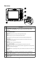
Overview 1 2 3 4 Key 1 Description CURSOR CONTROL: Move the cursor, scroll through menus, adjust features, view sonar/GPS history. 8 & 10 models also have a fly wheel to aid scrolling. CONTROL KEYS ZOUT: Zoom out to see more of the map with less detail ZIN: Zoom in to see less of the map with more detail. Pressing ZOUT & ZIN at the same time will activate Man Overboard mode. ENTER: Finalize menu selections; shortcut key for functions like saving a waypoint at cursor position.
1 2 Key 3 4 Description 1 Sonar (Not available on HDS5M, 7M, 8M or 10M units) 2 Power/Data 3 ENET (Ethernet) 4 NMEA2K (NMEA2000) Network 8
Display Installation Mounting location Choose the mounting locations carefully before you drill or cut. The display should be mounted so that the operator can easily use the controls and clearly see the display screen. Be sure to leave a direct path for all of the cables. The display screen is high-contrast and antireflective, and is viewable in direct sunlight, but for best results install the display out of direct sunlight. The chosen location should have minimal glare from windows or bright objects.
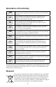
Bezel Removal 1: To removing the bezel from the 5 and 7-inch models the card slot door must be open 2: To remove the bezel use a flat head screwdriver. 3: Insert screwdriver into the bezel release slots and pry out and away from the unit. The bottom of the bezel will release from the unit. Push up to release the top bezel catches.
Panel Mount 1: Attach the flush mounting template to the selected mounting position using adhesive tape. 2: Drill pilot holes for the four hole saw 3: Use a hole saw to cut the four corner radius 4: Cut along the dotted line and remove the shaded area. 5: Connect all cables to the rear of the unit before placing the unit into the console.
Bracket Mount An alternative to flush mounting the HDS display is to bracket mount the unit. This method has the advantage that the display can be easily removed when not in use and may be tilted to achieve the best possible viewing angle. 1: Loosely screw securing knobs to the Display unit. 2: Temporarily mount the display unit in the bracket 3: Make sure the display can be adjusted to the correct angle without interfering with the surrounding.
8: Slide the display into the mounting bracket and secure in place with the bracket knobs. 9: 13 Attach the bezel. Firmly clip the front bezel in place.
Transducer Installation Recommended Tools and Supplies Tools and Supplies (not included) If you plan to route the transducer cable through the transom, you will need either a 1” drill bit or a 5/8” drill bit depending on the size of the transducer cable connector. Each transom mount requires a high quality, marine grade above- or below-waterline sealant/adhesive compound. The following installations also call for these recommended tools and supplies.
Skimmer Installation Instructions Transducer location and installation is one of the most critical steps in sonar installation. Select a transducer location To function properly the Skimmer transducer must be in the water at all times and in a location that has a smooth flow of water when the boat is moving. Poor location Good location Poor location Good location Note: Aluminum boats with strakes or ribs on the hull can create large amounts of turbulence at higher speeds.
Aligning Ratchets on Transducer bracket Aligning ratchets on one-piece bracket: The one-piece bracket assembly includes two black plastic ratchets. The ratchets are used to align the transducer with the boat hull. Each ratchet has the letters A-E molded into it. 1: Ratchet Insert the ratchets in the bracket with the letter "A" aligned with the dot stamped on the outside of the transducer bracket, as shown in the following series of diagrams. Bracket Align dot and letter "A".
Aligning ratchets on two-piece bracket The two-piece bracket includes four black plastic ratchets. The ratchets are used to align the transducer with the boat hull. Each ratchet has the letters A-F molded into it. If the transducer will not adjust with its face parallel to the ground. 1: Place two of the ratchets in each side of the bracket with the letter "A" aligned with the alignment mark molded into each bracket.
Assembling the Transducer bracket After determining the correct position for the ratchets, loosely assemble the transducer and bracket assembly as shown in one of the two diagrams below. One-piece bracket assembly Metal washer Lock nut Rubber washers Metal washer Ratchets Bolt Note: Do not tighten the transducer bracket assembly until you have aligned the transducer and bracket on the transom.
Aligning and Attaching the Transducer Adjust the transducer so that its "face" is parallel with the ground and its center line is even with the bottom of the boat hull. Transducer bracket mounted too high. Transducer bracket mounted too low. Transom Transom Bottom of hull. Bottom of hull. Note: When mounting the transducer to the transom, there are two extremes you should avoid, first, do not let the edge of the mounting bracket extend below the bottom of the hull, left image, above.
1: Hold the transducer and bracket assembly against the transom. When the transducer and bracket are properly aligned mark its position on the hull. 2: Drill the mounting holes for the transducer bracket. For the onepiece bracket use a #29 bit (for the #10 screws). For the two-piece bracket use a #20 bit (for the #12 screws). Note: Use the provided screws to secure the transducer assembly to the transom. Be sure to use a below-waterline marine grade sealant on all of the transducer bracket screw holes.
If you drill a hole in the transom for the transducer cable, make sure it is located above the waterline. Seal the hole with an above or below waterline marine grade sealant. Route the transducer cable to the sonar unit. Make sure to leave some slack in the cable near the transducer. Use caution when routing the transducer cable near other wiring and cables.
TMB-S Trolling Motor Bracket Installation Note: The TMB-S bracket is designed for one-piece bracket transducers only. The TMB-S trolling motor bracket (Part No. 51-45) is an optional accessory and is available through LEI Extras at www.lei-extras.com. The TMB-S bracket is used to attach a one-piece bracket transducer to a trolling motor. If you regularly fish in water with a lot of underwater structure, such as rocks, stumps and trees, you may consider using a Pod transducer for trolling motor installation.
Skimmer Transducer Shoot-thru-hull Installation Before attempting any installation on boats with flotation material sandwiched within the hull, consult the boat manufacturer. In a shoot-thru-hull installation the transducer is epoxied to the inside of the boat hull. WARNING: Do not remove any material from the inner hull. Careless grinding or cutting on the hull could damage the integrity of the hull. Contact the boat dealer or manufacturer to confirm hull specifications.
A transducer can not shoot through wood or metal hulls. Wood and metal hulls require either a transom mount or "thru-hull" installation. For shoot-thru-hull applications many boat hulls have a flat keel pad that offers a good transducer mounting surface. If you are using a Skimmer transducer versus a Pod transducer for this installation, make sure the Skimmer transducer is oriented so the nose of the transducer is facing the bow (front) of the boat.
Pod Transducer Installation Instructions The following instructions explain how to install a Pod transducer inside a hull or on a trolling motor. Read the following instructions carefully before attempting any installation. Use extreme care when mounting a transducer inside a boat hull. Once epoxied into position, the transducer can be very difficult to remove. Note: Transducer location and installation is one of the most critical steps in sonar installation.
On vee hulls try to place the transducer where the deadrise is 10° or less. 1: 2: 3: Sand both the inside surface of the hull, where the transducer is to be epoxied, and the face of the transducer. Sand face of transducer and bottom of hull. You may want to start with a rougher grit sandpaper, such as 60 grit, and finish with a smoother grit, such as 160 grit, sandpaper. Sand the inside surface of the hull until it is smooth to the touch.
Pod Transducer Trolling Motor Installation The top of the transducer is curved to fit the contour of the trolling motor. You will need a hose clamp large enough to fit over the trolling motor. The hose clamp is NOT included with the Pod transducer. Before you attach the transducer to the trolling motor, make sure there is enough slack in the transducer cable for the trolling motor to turn freely. 1: Slide the hose clamp through the Pod transducer brackets, as shown below.
System Architecture This section explains how the HDS connects to other devices as part of a system. The HDS has a highly scalable system architecture. A system can consist of a basic stand alone fishfinder or chart plotter, or expand to a networked, multi-display system connected to a wide range of accessories. Networking, Data Interfacing The HDS display can connect to other devices in the system by Ethernet, NMEA 2000 or NMEA 0183.
Wiring the HDS Wiring Guidelines Most installation problems are caused by shortcuts taken with system cables. When wiring the HDS follow the guidelines below.
Power/Data Cable Power / Data cable Yellow (Accessory Wake Up) Power (3 wire) Data cable (5 wire) NMEA0183 Wiring RS-422 All HDS Units Yellow TX (+) BLUE TX (-) Orange (RX+) Red (FUSE) Black Com 1 Green (RX-) Shield (ground) + _ Alternative NMEA0183 Wiring RS-232 HDS 8 & HDS 10 12 V DC Yellow (TX) Orange (RX) Com 1 Shield (ground) Common BLUE (TX) Green (RX-) Com 2 The power cable from each device contains a yellow wire. The yellow wire is the accessory wake up line.
NMEA 0183 Wiring Table RS-422 HDS Device Green RX (-) Transmit (-) Orange RX (+) Transmit (+) Shield (Ground) Ground Yellow TX (+) Receive (+) Blue TX (-) Receive (-) RS-232 HDS-8 & 10 Only — (COM 1) HDS Device Yellow TX Receive Orange RX Transmit Shield (Ground) Ground RS-232 HDS-8 & 10 Only — (COM 1) HDS Device Blue TX Receive Green RX Transmit Shield (Ground) Ground NMEA 0183 wiring HDS-5 & HDS-7 Data Cable To exchange NMEA 0183 data, the HDS-5 and HDS-7 units have a NMEA 0183 v
NMEA 2000 wiring All NMEA 2000 systems must consist of 12V power, two (2) 120 Ohm terminators (one on each end of the network), T joiners and NMEA 2000 Devices. Lowrance offers a NMEA 2000 starter kit (000-0124-69) that includes two (2) terminators, two (2) T connectors, one (1) 2ft extension/drop cable, one (1) 15ft extension cable and one (1) power node.
Ethernet The HDS system uses an Ethernet network to interconnect high bandwidth devices such as other HDS displays, radar and sonar. Each HDS display has one network port with 5 pin connector. Ethernet network has orange connectors that are retained by a bayonet type locking collar. If more than two network devices need to be connected, use the optional Network Expansion Port (NEP).
HDS-8 & HDS-10 Data Bridging Supported NMEA0183 sentences entering the system are bridged (converted) to NMEA2000 and distributed on the Lowrance backbone for all other displays to use. Certain NMEA2000 PGNs (messages/sentences) are bridged across to NMEA0183 to be available as an output from any HDS display. Refer to the NMEA 0183 table in the back of this manual to view bridgable sentences.
Single Station Single station configuration possibilities POWER Red (FUSE) Optional accessory Supplied with display NMEA2000 Devices LGC-4000 GPS Receiver Temperature Sensor Fluid Level Sensor Fuel Flow Sensor Pressure Sensor Heading Sensor/Compass Engine Interface SonicHub Audio Server LMF Gauges VHF Radio Black Yellow HDS Display Blue No Connect +_ Wake up wire Used to turn on accessories 10 - 17 V DC Power/Data Cable NMEA0183 NMEA2000 RS-422 HDS Green RX (-) Orange RX (+) Shield (ground) Yel
Dual & Multi Station Dual station configuration possibilities Supplied with display NMEA0183 Optional accessory RS-422 HDS Green RX (-) Orange RX (+) Shield (ground) Yellow TX (+) Blue TX (-) Device Transmit (-) Transmit (+) Ground Receive (+) Receive (-) RS-232 HDS-8/10 only Com 1 Com 2 HDS Yellow TX Orange RX Shield (ground) Device Receive Transmit Ground HDS Blue TX Green RX Shield (ground) Device Receive Transmit Ground Power/Data Cable NMEA2000 Network Expansion Port NEP-2 Network Expansio
Connecting HD Radar 12 V DC ONLY B Scanner D C Ethernet HEADING In D A E F G J I H G _ + K K L Key L Description A HDS Display. B LRA1800 &LRA2400 HD radar system for HDS. Includes parts C,D and E. 2kw & 4 kW Radome. C Scanner cable. 15 m (50 ft) An Optional 20 m (65ft) cable is available D HD Radar Processor E Ethernet cable RJ45 (male/male). Available in 2, 5 and 10 m, (6.5, 16.5 & 33 ft) F Ethernet Adapter cable. Yellow 5 pin (Male) to RJ45 (female) 2 m (6 ft).
Connecting BR24 Radar B D SimNet Network Power Scanner cable C D A E F G H F _ + I J Key I J Description A HDS Display. B BR24 BroadBand™ Radar system for HDS. Includes parts B, C and D (not included in US) and E (2 m 6ft) C Scanner cable. 10 m (33 ft) : Optional 20 m (65 ft) and 30 m (98 ft). D RI10 Radar interface box (Used with MARPA) (Not included with US version) E Ethernet cable. BR24 comes with a 2 m (6.
Commissioning Check List Commissioning your system will improve the functionality and operation of your unit. The following pages will give you an overview of the minimum settings we recommend you set up before you start operating your HDS. Please refer to the HDS operations guide for more information on how to change these settings. Language Select the language used on menus and dialog boxes. The default language is English. Units Select which unit type you would like the HDS to display data in.
Selecting a Fishing Mode Fishing modes enhance the performance of your unit by providing preset packages of sonar settings geared to specific fishing conditions. To select a fishing mode: Press Menu twice. Select Sonar and press enter. Highlight Fishing Mode and press enter. S elect the desired fishing mode and press enter.
Magnetic Variation Converts magnetic north data to true north, increasing the accuracy of navigation information. The Magnetic Variance Auto setting, automatically converts magnetic north to true north. Note: When using manual mode, you will have to input the magnetic variance. Satellites Monitors the location of satellites in view and the quality of the unit’s satellite lock-on. The Satellite page has two display options.
Water speed off set Water speed calibration is used to adjust the speed value from the paddle wheel to match the actual speed. This can be measured either from the GPS speed over ground (SOG) or by timing the boat over a known distance. Water speed calibration should be performed with as little wind and current movement as possible. Select Auto correct to match water speed to ground speed Manual calculation. If in average the water speed reads 8.5 knots and SOG records 10 knots. Increase the offset to 117%.
184 mm (7.24") 145.4 mm (5.72") 151.8 mm (5.97") 30 mm (1.18") 56.9 mm (2.24") 58 mm (2.
223 mm (8.78") 163.9 mm (6.45") 196.9 mm (7.75") 30.79 mm (1.21") 60 mm (2.36") 57.5 mm (2.
269 mm (10.59") 197.2 mm (7.76") 205.9 mm (8.11") 31.4 mm (1.24") 64 mm (2.52") 61 mm (2.
311.8 mm (12.28") 224.9 mm (8.85") 229.3 mm (9.03") 34.3 mm (1.35") 64 mm (2.52") 58 mm (2.
NMEA Information NMEA 2000 PGN List NMEA 2000 PGN Transmit 126208 126992 126996 127237 127250 127258 128259 128267 128275 129025 129026 129029 129283 129284 129539 129540 130074 130306 130310 130311 130312 130577 61184 130840 130845 130850 65287 65289 65290 65292 65293 130818 130819 130828 130831 130835 130836 130837 130839 130845 130850 ISO Command Group Function System Time Product Info Heading/Track Control Vessel Heading Magnetic Variation Speed, Water referenced Water Depth Distance
NMEA 2000 PGN Receive 59392 59904 60928 60928 126208 126992 126996 127237 127245 127250 127251 127257 127258 127488 127489 127493 127505 127508 128259 128267 128275 129025 129026 129029 129033 129038 129039 129040 129283 129284 129539 129540 129794 129801 ISO Acknowledgement ISO Request ISO Address Claim ISO Address Claim ISO Command Group Function System Time Product Info Heading/Track Control Rudder Vessel Heading Rate of Turn Attitude Magnetic Variation Engine Parameters, Rapid Update Engine
Supported NMEA 0183 sentences TX / RX GPS Receive GGA GLL GSA GSV VTG ZDA Transmit GGA GLL GSA GSV VTG ZDA Navigation Receive RMC Transmit AAM APB BOD BWC BWR RMC Echo Receive DBT DPT MTW VLW VHW Transmit DBT DPT MTW VLW VHW Compass Receive HDG Transmit HDG HDT HDM Wind Receive MWV Transmit MWV Receive DSC MWD AIS / DSC DSE VDM AIS sentences are not bridged MARPA Transmit TLL TTM These are only out put sentences 49 RMB XTE
Visit our website: www.lowrance.