Pub.
Copyright © 2008 Navico. All rights reserved. No part of this manual may be copied, reproduced, republished, transmitted or distributed for any purpose, without prior written consent of Navico. Any unauthorized commercial distribution of this manual is strictly prohibited. Lowrance® is a registered trademark of Navico. NMEA 2000® is a registered trademark of the National Marine Electronics Association. Navico may find it necessary to change or end our policies, regulations and special offers at any time.
Table of Contents Warnings and Cautions .......................................................... iii Section 1: Introduction............................................................. 1 Software Update............................................................................ 1 Checking Software Version....................................................... 1 To download software update to MMC/SD card: ................. 1 To update display unit software: ..........................................
Log Radar Data ....................................................................... 18 Radar Setup ............................................................................. 22 Radar Orientation ................................................................... 22 Radar Color Scheme................................................................ 22 Adjust Antenna Park .............................................................. 22 Radar Information...................................................
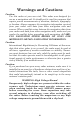
Warnings and Cautions Caution: Use this radar at your own risk. This radar was designed for use as a navigation aid. It should not be used for purposes that require precise measurements of direction, distance, topography or location. Always compare the navigation information received from your radar with data from other navigation aids and sources.
WARNING: Microwave Radiation Hazard The microwave energy radiated by a radar antenna is harmful to humans, especially to the eyes. NEVER look directly into an open waveguide or into the path of radiation from an enclosed antenna. Radar and other radio frequency radiation can upset cardiac pacemakers. If someone with a cardiac pacemaker suspects abnormal operation, immediately turn off the radar equipment and move the person away from the antenna.
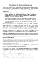
Section 1: Introduction Your radar consists of four components: the radar scanner unit (antenna), your display unit (sold separately) radar processor and RIM 300 radar interface module. This manual covers LRA-1800 and LRA-2400 radars. WARNING: Radar radiation can be harmful to you and bystanders. Radar misuse or misunderstanding radar operation could lead to a collision, which could result in property damage, personal injury or death.
3. Select your display unit icon and choose DOWNLOADS. Click on the DOWNLOAD button next to the desired software update. 4. Follow the onscreen installation instructions to download the update onto your MMC/SD card. To update display unit software: 1. With the display unit turned off, install the MMC or SD card that contains the radar software update. 2. Turn on the unit and the update will install automatically. 3. When the update is finished, the unit will power up normally.
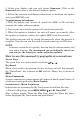
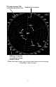
Basic Radar Display Components Range Range Ring Interval Anti-Sea Clutter Display mode Gain level Interference Rejection status Anti-Rain Clutter Radar Cursor Boxes Echo Trail status Radar Echo Expansion status Electronic Bearing Lines Variable Range Markers Your unit has three electronic bearing lines and three variable range markers. An enlarged example of EBLs and VRMs is on the next page. Variable Range Marker position for VRMs 1, 2 and 3.
PPI (radar screen's 360º overhead view of the area) Heading line (in green) EBL2 EBL3 EBL1 VRM1 VRM2 VRM3 Bearings, in degrees (in Heading Up mode, relative to bow) VRMs and EBLs allow you to track the distance and bearing of multiple radar targets.
Section 2: Radar Setup Before you begin radar setup, the radar scanning unit, RIM 300 module, radar processor and display unit all must be installed. WARNING: Do NOT attempt to execute Radar Setup, while the vessel is moving. Some motion from wind and wave action is acceptable, but these setup instructions are NOT intended for vessels moving across the water.
To access Radar Page: 1. Press PAGES, then use ← → to select the radar tab. 2. Press ↓ to select RADAR ONLY then press EXIT. Radar only highlighted on Radar Pages menu (left). Radar menu with Radar Power selected (right). 3. Press MENU, then use ↑ ↓ to select RADAR POWER from the radar menu and press ENT. A confirmation message will appear. Press ← to select YES and press ENT. A warm-up countdown will commence that will vary depending on the model of radar you have. 4.
8. Use ↑ ↓ to highlight one of the three full color options and press ENT. Press EXIT to return to the main page display. Auto Power-On When the Auto Power-on feature is turned on, the radar will start warming up every time the display unit is turned on. Access the Communications Port menu to turn on or turn off the Auto Power-on feature. Caution: If you do not plan to use your radar every time the display unit is turned on, you need to turn off the Auto Power-On feature. Turning on/off Auto Power-On: 1.
We will set them up in that order, but before making any adjustments, make sure the display is set to a range of 0.125 nautical miles and that Gain, Anti-Sea Clutter (STC), Anti-Rain Clutter (FTC) and Trigger Delay all have been set to zero percent. Trigger Delay Preparation Range 1. To reset range to 0.125 nm, make sure you are on the Radar Only page and press MENU. 2. Use ↑ ↓ to select RADAR RANGE and press ENT, which will call up the Radar Range list. Press ↑ to select 0.125 nm and press ENT.
2. Press →|↓ to ADJUST TRIGGER DELAY and press ENT. That will launch the Adjust Trigger Delay vertical scrollbar. 3. Press ↓ until Trigger Delay is set to zero percent. Press EXIT. Adjust Trigger Delay This feature eliminates the time lag between real radar returns and the time it takes data to be processed by the radar software, a common issue with all radars. Caution: If you have any doubt about your understanding of the Trigger Delay feature, you should have it set up by a qualified radar technician. 1.
4. Press ↑ to increase the level of Trigger Delay, which will decrease the size of the ring. If you have a 4 kW radar, as the large ring decreases in size, the smaller ring in the center of the screen will disappear, leaving only one ring. Increase Trigger Delay to diminish the size of the red ring (left). To set Trigger Delay correctly, reduce the ring to as small a size as possible, while keeping a black circle in the middle (enlarged view, right).
1. Line up the bow of your vessel with a point of reference, like a peninsula, lighthouse or other stationary target. 2. Press MENU, highlight RADAR SETUP and press ENT. Press → to select ADJUST HEADING LINE and press ENT. That will place an arrow on each side of the green Heading Line. 3. Use ← → to adjust the position of the green heading line, so its line to the reference point's radar image matches your bow's actual line to the reference point. 4.
Notes 12
Section 3: Basic Operation Pages The Radar Page has six display options: Radar Only, Digital Data, Radar with Map, Radar with Sonar, Radar with Gauges and Radar, Map and Sonar. GPS only units do not support the Radar with Sonar page, so they have four display options: Radar Only, Digital Data, Radar with Map and Radar with Gauges. Radar Page Menu with Radar Only selected. To access Radar page display options: 1. Press PAGES, then use ← → to highlight the radar tab. 2.
Digital Data page (left) with Radar with Map display (right). NOTE: When more than one page display is on the screen at the same time, press PAGES|PAGES to switch the Active status between windows. The title bar at the top of the window will be blue when the window is active. The only exception is the map page, which will display "Active Map" at the top of the map. Radar with Sonar The Radar with Sonar option allows you to monitor radar information, while viewing sonar returns.
Radar, Map and Sonar page display. Radar, Map and Sonar The Radar, Map and Sonar page is broken up into three windows, allowing you to monitor the radar, map and sonar simultaneously. Radar Menu When a radar page is the active page, you can access the radar menu by pressing MENU. To access the main menu, press MENU|MENU. Radar Menu. Gain The Gain feature allows you to adjust the sensitivity of the receiver.
NOTE: When adjusting Gain back to a useable level, increase the level until you see a light peppering of echoes on the display. Also remember, you will have to adjust gain every time you change ranges. To adjust Gain: 1. Press PAGES, select the Radar tab and press ENT. 2. Press MENU, highlight GAIN and press ENT. 3. Use ↑ ↓ to adjust the Gain to a desired level. Press EXIT. Gain vertical scrollbar (left) with Anti-Sea Clutter scrollbar (right).
WARNING: Increasing FTC may reduce or eliminate weak echoes, like those from small vessels. Use only the minimum amount needed, then check back periodically to see if the FTC level may be decreased. Anti-Rain Clutter vertical scrollbar (left) with Interference Rejection scrollbar (right). Interference Rejection This feature filters out signals from other radars close to your location. To adjust Interference Rejection: 1. Press MENU, select INTERFERENCE REJECTION and press ENT. 2.
To adjust radar range: 1. Press MENU, select RADAR RANGE and press ENT. 2. Use ↑ ↓ to select the desired range and press ENT. NOTE: When switching radar ranges, you likely will need to adjust Gain, STC and FTC settings to achieve optimum performance. Tip: You can also adjust radar range by pressing the ZIN or ZOUT keys. Radar Echo Expansion The Radar Echo Expansion feature will make weak signals more visible on the display by lengthening radar echoes. To turn Radar Echo Expansion On/Off: 1.
GlobalMap 8300cHD and GlobalMap 9300cHD) the Log Radar Data feature will be available on the Radar menu, allowing you to save radar logs. Saving a radar log allows you to reuse the log in the unit's simulator. If your unit does not have a hard drive you will not see the Log Radar Data command on your Radar menu. Log Radar Data menu. To record a radar log: 1. Press MENU, select LOG RADAR DATA and press ENT. 2. Press ENT to start logging.
Browse Files selected from the Radar Chart Logging menu (left). Browse Files menu (right). To copy data files: 1. Press MENU, select LOG RADAR DATA and press ENT. Select BROWSE FILES and press ENT. 2. Select the desired file and press ENT. 3. The File Information window will appear with three buttons, copy, delete and either stop or play. File Information window (left). The Copy To window (right). NOTE: Stop will only appear in the File Information menu if the file is in use. 3.
2. Select the desired file from the Browse Files menu and press ENT. 3. Highlight DELETE from the File Information window and press ENT. 4. A confirmation message will appear. Press ← to YES and press ENT. To stop or play a data file: 1. Press MENU, select LOG RADAR DATA and press ENT. Select BROWSE FILES and press ENT. 1. Select the desired file from the Browse Files menu and press ENT. 2. If the file is currently in use, the STOP button will be on the menu. Otherwise the PLAY button will be displayed.
Radar Setup The Radar Setup menu allows you to set up and adjust basic radar settings, like Heading Line, Trigger Delay and Tune, all of which are addressed in the section on Radar Setup. You can also modify Radar Orientation, Radar Color Scheme and Antenna Park from the Radar Setup menu. Radar Orientation The Radar Orientation feature, displays the orientation of your radar, which by default is set to Heading Up. To select radar orientation: 1. Press MENU, select RADAR SETUP and press ENT. 2.
Selecting Adjust Antenna Park will place a dialog box in the upper right-hand corner of the screen. Use Arrow keys to adjust it. NOTE: There is no recommended setting for Antenna Park. Use the trial and error method when adjusting antenna park. Repeat the process until the antenna comes to a stop in the desired position. To adjust Antenna Park: 1. Before adjusting Antenna Park, make sure your vessel is stationary. From the Radar Page, press MENU, select RADAR SETUP and press ENT. 2.
Radar Power Turns the radar on and off. To turn the radar on or off: 1. Press MENU, select RADAR POWER and press ENT. 2. A confirmation message will appear. Select YES and press EXIT. Radar Simulator Your unit has a simulator that allows you to get familiar with radar operation before heading out on the water. Simulators highlighted on the System Setup menu (left). Radar Simulator On selected on Radar Simulator menu (right). Notice the simulator has not been turned on, since the checkbox is unchecked.
Radar Overlay The Radar Overlay feature allows you to overlay radar data on any map page as long as you have a valid GPS position and a NMEA 2000 heading sensor or compatible NMEA 0183 heading sensor. NOTE: You will need to purchase a SIMRAD heading sensor for the Radar Overlay feature to work properly. To use Radar Overlay: 1. Press PAGES, highlight the MAP tab and press ENT. 2. Press MENU, highlight ENABLE RADAR OVERLAY and press ENT|EXIT. 3. To turn off Radar Overlay, repeat Step 2.
2. Highlight RADAR OPTIONS and press ENT to access the Radar Options menu. To use the features on the Radar Options menu, refer the Radar Menu instructions covered earlier in this section. Overlay Options menu The Overlay Options menu allows you to turn on overlay transparency, select a transparency level, and choose the color of the radar overlay. Radar Overlay Options menu (left) Radar Overlay in use on Radar with Map page. To access Overlay Options menu: 1.
Section 4: Advanced Operation Radar Only page display. Reading the Display The radar page displays digital information on the screen which covers, Range Rings, Gain, Anti-Sea Clutter (STC), Anti-Rain Clutter (FTC) and when active, Electronic Bearing Lines (EBL) and Variable Range Markers (VRM). Gain The percentage listed next to Gain, displays the current Gain setting for your radar display.
Anti-Sea Clutter (STC) The STC percentage displays the current Anti-Sea Clutter setting on your radar screen. Anti-Rain Clutter (FTC) The FTC percentage displays the current Anti-Rain Clutter setting on your radar screen. Electronic Bearing Line (EBL) A radial line that can be rotated 360°, the electronic bearing line is used to monitor the bearing of a radar target in relation to your location. The EBL and VRM selection menu appears in a small box on the left side of the radar display (left).
Radar Cursor Boxes Radar cursor The Radar Cursor boxes are show in white in the top, left-hand corner. The Radar Cursor is aligned with a target in the bottom-right portion of the screen 3. Press ENT to launch the EBL/VRM menu. Use ↑ ↓ to select the desired EBL and VRM and press ENT twice. Press EXIT. The Radar Cursor coordinates have been assigned to the EBL/VRM you selected. The EBL and VRM coordinates will be listed in the bottom left and right-hand corners of the display. 4.
VRM (Variable Range Marker) Radar Cursor Boxes Radar cursor EBL (Electronic Bearing Line) EBL L VRM The Variable Range (VRM) shows the target is 0.219 nautical miles away. The Electronic Bearing Line (EBL) displays the target's bearing as 099.9ºR. To reposition an EBL/VRM: 1. Press ENT to launch the EBL/VRM menu. Select the EBL/VRM you would like to change and press ENT. 2. Press ↑ ↓ to increase or decrease the size of the circular VRM.
VRM (Variable Range Marker) Radar Target EBL (Electronic Bearing Line) This is a zoomed in view from the previous image, clearly showing the radar target, Variable Range Marker and Electronic Bearing Line. To remove an EBL/VRM from the display: 1. Press ENT to call up the EBL/VRM menu. Select the EBL/VRM you want to remove and press ENT. 2. Press EXIT and the desired EBL/VRM will be removed from the screen. 3. Repeat these steps to remove each EBL/VRM from the display.
VRM2 EBL2 EBL3 VRM3 VRM1 EBL1 When using multiple EBL/VRMs, the size of the dashes and the distance between dashes allows you to distinguish between the different EBL/VRMs on the display.
Appendix I: Glossary Anti-Rain Clutter (FTC): used to reduce or eliminate massive number of small echoes that clutter the display during rain or snow storms. Anti-Sea Clutter (STC): lowers receiver sensitivity at shorter ranges to reduce or eliminate sea clutter echoes, which are most prevalent around the vessel. Beam: focused rays of microwave energy Beam width: measured in degrees, the width of a beam, both horizontally and vertically.
North Up: a stabilized display mode in which North is at the top of the radar display. This display mode requires a heading sensor. Offset EBL: an electronic bearing line originating from a location other than the PPI sweep origin. Open Array Antenna: a radar antenna which has an external rotating scanner. PPI (Plan Position Indicator): The PPI provides a map-like representation of target echoes. Radar Overlay: radar image data laid over an electronic chart.
Notes 35
Notes 36
Notes 37
FCC Compliance This device complies with Part 15 and Part 80 of the U.S. Federal Communications Commission (FCC) Rules. Operation is subject to the following two conditions: (1) this device may not cause harmful interference, and (2) this device must accept any interference received, including interference that may cause undesired operation. Changes or modifications not expressly approved by the manufacturer could void the user's authority to operate the equipment.
NAVICO FULL ONE-YEAR WARRANTY "We," "our," or "us" refers to NAVICO, the manufacturer of this product. "You" or "your" refers to the first person who purchases this product as a consumer item for personal, family or household use. We warrant this product against defects or malfunctions in materials and workmanship, and against failure to conform to this product's written specifications, all for one (1) year from the date of original purchase by you.
How to Obtain Service… …in the USA: We back your investment in quality products with quick, expert service and genuine Lowrance parts. If you're in the United States and you have technical, return or repair questions, please contact the Factory Customer Service Department. Before any product can be returned, you must call customer service to determine if a return is necessary. Many times, customer service can resolve your problem over the phone without sending your product to the factory.
Accessory Ordering Information for all countries To order Lowrance accessories for your unit, please contact: 1) Your local marine dealer or consumer electronics store. Most quality dealers that handle marine electronic equipment or other consumer electronics should be able to assist you with these items. To locate a Lowrance dealer near you, visit our web site, www.lowrance.com and look for the Dealer Locator. Or, you can consult your telephone directory for listings. 2) U.S. customers: LEI Extras Inc.
Visit our web site: Lowrance Pub.