ELITE Ti Operator Manual ENGLISH lowrance.
Preface Disclaimer As Navico is continuously improving this product, we retain the right to make changes to the product at any time which may not be reflected in this version of the manual. Please contact your nearest distributor if you require any further assistance. It is the owner’s sole responsibility to install and use the equipment in a manner that will not cause accidents, personal injury or property damage. The user of this product is solely responsible for observing safe boating practices.
Additional mapping data: Copyright© 2012 NSI, Inc.: Copyright© 2012 by Richardson’s Maptech. Bluetooth® is a registered trademark of Bluetooth SIG, Inc. Power-Pole® is a registered trademark of JL Marine Systems, Inc. C-Monster™ is a trademark of JL Marine Systems, Inc.
received, including interference that may cause undesired operation. The relevant Declaration of conformity is available on the following website: lowrance.com. About this manual This manual is a reference guide for operating the ELITE Ti. It assumes that all equipment is installed and configured, and that the system is ready to use. The manual assumes that the user has basic knowledge of navigation, nautical terminology and practices.
Use the menu options or the keys and on-screen buttons to maneuver in the PDF file as described below: • Search, Goto page, Page Up and Down Select the relevant panel button. • Scroll pages Drag finger on the screen in any direction. • Panning on the page Drag finger on the screen in any direction. • Zoom In/Out Key operation: Use the + and - keys. • Exit the PDF viewer Select the X in the upper right corner of the panel.
The Software version The software version currently on this unit can be found in the About dialog. The About dialog is available in the System Settings. For more information, refer to "About" on page 110. For upgrading your software, refer to "Software upgrades" on page 115.
Preface | ELITE Ti Operator Manual
Contents 13 Introduction 13 14 15 16 Front controls The Home page Application pages Power-Pole anchors 19 Basic operation 19 19 20 20 20 21 21 23 24 System Controls dialog Turning the system on and off Display illumination Locking the touchscreen Using menus and dialogs Selecting pages and panels Using the cursor on the panel Creating a Man Overboard waypoint Screen capture 25 Customizing your system 25 25 26 26 27 Customizing the Home page wallpaper Adjusting panel size Data Overlay Adding new favorit
34 35 39 44 Insight charts Navionics charts Jeppesen charts Chart settings 47 Waypoints, Routes, and Trails 47 47 49 52 Waypoints, Routes, and Trails dialogs Waypoints Routes Trails 53 Navigating 53 54 54 55 56 Steer panel Navigate to cursor position Navigate a route Navigating with the autopilot Navigation settings 58 Sonar 58 59 59 59 60 62 62 63 64 65 66 68 The Sonar image Zooming the image Using the cursor on the image Viewing history Setting up the image Stop sonar Advanced options Start recordi
76 StructureMap 76 76 77 78 78 79 80 The StructureMap image Activating Structure overlay StructureMap sources StructureMap tips Recording StructureScan data Using StructureMap with mapping cards Structure options 82 Info panels 82 82 Dashboards Customizing the Info panel 84 Trolling motor autopilot 84 85 85 86 90 Safe operation with the autopilot Switching from automatic navigation to standby mode Autopilot interface Autopilot control of the trolling motor Autopilot settings 92 Wireless connection 92
105 Alarms 105 105 105 105 106 106 Alarm system Type of messages Single alarms Multiple alarms Acknowledging a message Alarms dialog 108 Tools 108 108 108 108 111 111 112 112 112 112 Waypoints/routes/trails Tides Alarms Settings Vessels Sun, Moon Trip calculator Files Find GoFree Shop 114 Maintenance 114 114 114 114 115 116 Preventive maintenance Checking the connectors Touchscreen calibration NMEA Data logging Software upgrades Backing up your system data 119 Simulator 119 Demo mode 119 Simulator sou
1 Introduction Front controls 1 2 3 4 5 6 1 Touch screen 2 Pages 3 Zoom out / Zoom in (combined press = MOB) 4 New waypoint (long press = Find dialogue) 5 Power button Press and hold to turn the unit ON/OFF. Press once to display the System Controls dialog.
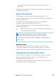
The Home page The Home page is accessed from any operation by a short press on the Pages key. 14 1 Tools Select a button to access dialogs used for carrying out a task, or for browsing stored information. 2 Local time and Water depth 3 Applications Select a button to display the application as a full page panel. Press and hold a button to display pre-configured split page options for the application. 4 Close button Select to exit the Home page and return to the previous active page.
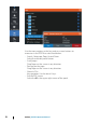
Application pages Each application connected to the system is presented on panels. The application can be presented as a full page, or in combination with other panels in a multiple panel page. All application pages are accessed from the Home page. 1 Application panel 2 Menu Panel specific menu. 3 System Controls dialog Quick access to basic system settings. Display the dialog by a short press on the Power key. 4 Dialog Information to or input from the user.
Panel sizes in a split page can be adjusted from the System Controls dialog. Quick split pages Each full screen application has several pre-configured quick split pages, featuring the selected application combined with each of the other panels. Ú Note: The number of quick split pages cannot be changed, and the pages cannot be customized or deleted. Access a quick split page by pressing and holding the application button on the Home page.
Power-Pole controls When Power-Poles are paired with the ELITE Ti, the Power-Pole button becomes available in the System Controls dialog. Select it to display the Power-Pole controller. For pairing Bluetooth devices, refer to "Pairing Bluetooth devices" on page 94. If you are pairing dual Power-Poles, also review "Pairing with dual Power-Poles" on page 95. When the Power-Pole controller is opened, the system connects to paired Power-Poles. When the connection is confirmed the control buttons are enabled.
Stay connected Select the Stay connected (cog) button on the Power-Pole controller to open the Power-Pole settings dialog where you can select to stay connected to all paired Power-Pole anchors. Ú 18 Note: Selecting to Stay connected speeds up access to the controls, but the anchors cannot be controlled from another display when it is selected. Turn off this option to allow connection from other displays.
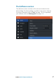
2 Basic operation System Controls dialog The System Controls dialog provides quick access to basic system settings. You display the dialog by making a short press on the Power key. Activating functions Select the icon of the function you want to set or toggle on or off. For those functions that toggle on and off, an orange bar across the top of the icon indicates the function is activated, as shown in the Data Overlay icon above.
Display illumination Brightness The display backlighting can be adjusted at any time from the System Controls dialog. You can also cycle the preset backlight levels by short presses on the Power key. Night mode The night mode option optimizes the color palette and backlight for low light conditions. Ú Note: Details on the chart may be less visible when the Night mode is selected! Locking the touchscreen You can temporarily lock a touchscreen to prevent accidental operation of the system.
When you hide a menu on one page, the menu on other pages is also hidden. To display the menu again, select the menu option. The status of the cursor (active vs. inactive) changes the menu options. Dialog boxes Numeric and alphanumeric keyboards are automatically displayed when required for entering user information in dialogs. A dialog is closed by saving or cancelling the entry. A dialog can also be closed by selecting the X in the dialog's upper right corner.
By default, the cursor is not shown on the panel. Position the cursor by tapping the desired location on the screen. When the cursor is active, the cursor position window is displayed. To remove the cursor and cursor elements from the panel, select the Clear cursor option. GoTo cursor You can navigate to a selected position on the image by positioning the cursor on the panel, then using the Goto Cursor option in the menu.
- The measuring icons appear with a line drawn from the vessel center to the cursor position, and the distance is listed in the cursor information window. 2. You can reposition the measuring points by dragging either icon as long as the measuring function is active Ú Note: The bearing is always measured from the grey icon to the blue icon. You can also start the measuring function without an active cursor. Both measuring icons are then initially located at the vessel position.
The MOB waypoint menu option When an MOB waypoint is activated, you can use the Waypoint MOB menu option to: • Move it on the panel • Edit its attributes • Delete it • Goto it When you select the Edit menu option the Edit Waypoint dialog opens. Screen capture Simultaneously press the Pages and Power keys to take a screen capture. Screen captures are saved to internal memory. To view files, refer to "Files" on page 112.
3 Customizing your system Customizing the Home page wallpaper The Home page's wallpaper can be customized. You can select one of the pictures included with the system, or you can use your own picture in .jpg or .png format. The images can be available on any location that can be seen in the files browser. When a picture is chosen as the wallpaper, it is automatically copied to the Wallpaper folder. Adjusting panel size You can change the panel size for an active split page.
The changes are saved to the active favorite or split page. Data Overlay You can have data information as overlay on a page. The information can be any data available on the network. Turning Data overlay on and off You can turn overlay data on or off for any active page by selecting the Data overlay icon on the System Controls dialog. When Data overlay is on, an orange bar appears above the icon.
2. Drag and drop page icons to set up a new page 3. Change the panel arrangement (only possible for 2 or 3 panels), if required 4. Save the page layout. The system displays the new favorite page, and the new page is included in the list of favorite pages on the Home page. Edit favorite pages 1. Select the edit icon in the Favorite panel: - Select the X icon on a favorite icon to remove the page - Select the tool icon on a favorite icon to display the page editor dialog 2.
4 28 Charts The chart function displays your vessel’s position relative to land and other chart objects. On the chart panel you can plan and navigate routes, place waypoints, and display AIS targets. You can also overlay a StructureScan image.
* Optional chart items. You turn the optional chart items on/off individually from the Chart settings dialog. Chart data The system is delivered with different embedded cartography depending on region. All units support Insight charts from Navico including Insight Genesis. The system also supports charts from Navionics and Jeppesen as well as content created by a variety of third party mapping providers in the AT5 format. For a full selection of available charts, visit gofreeshop.com, c-map.jeppesen.
Chart range scale and range rings interval (when turned on) are shown in the lower right corner of the chart panel. Panning the chart You can move the chart in any direction by dragging your finger on the screen. Select the Clear cursor menu option to remove the cursor and cursor window from the panel. This also centers the chart to the vessel position. Positioning the vessel on the chart panel Chart orientation Several options are available for how the chart is rotated in the panel.
Look ahead Moves the vessel icon closer to the bottom of the screen so that you can maximize your view ahead. Displaying information about chart items When you select a chart item, a waypoint, a route, or a target, basic information for the selected item is displayed. Select the chart item's pop-up to display all available information for that item. You can also activate the detailed information dialog from the menu.
Creating routes You can create routes as follows on the chart panel. 1. Position the cursor on the chart panel 2. Select New followed by New route in the menu 3. Continue positioning the remaining routepoints 4. Save the route by selecting the save option in the menu. Ú Note: For more information, refer to "Waypoints, Routes, and Trails" on page 47. Find objects on chart panels You can search for other vessels or various chart items from a chart panel.
Panning the 3D chart You can move the chart in any direction by selecting the Pan icon and then panning in the desired direction. Select the Return to vessel menu option to stop panning, and to center the chart to vessel position. Controlling the view angle You can control the view angle by selecting the Rotate icon and then panning the chart panel.
Insight charts Insight specific chart options Orientation, Look ahead, 3D, and change Chart source (previously described in this section) are common for all chart types. Chart imagery style The charts can be displayed in three imagery styles. 2D mapping style Shaded relief No contours Insight view options Chart detail • Full All available information for the chart in use. • Medium Minimum information sufficient for navigation.
Land Exaggeration and Water Exaggeration Graphical settings available in 3D mode only. Exaggeration is a multiplier applied to the drawn height of hills on land, and troughs in water to make them look taller or deeper. Navionics charts Navionics specific chart options Orientation, Look ahead, 3D and change Chart source (previously described in this section) are common for all chart types. Community edits Toggles on the chart layer including Navionics edits.
Presentation type Provides marine charting information such as symbols, colors of the navigation chart and wording for either International or U.S. presentation types. Chart details Provides you with different levels of geographical layer information. Safety depth The Navionics charts use different shades of blue to distinguish between shallow and deep water. Safety depth, based on a selected limit, is drawn without blue shading.
Dynamic tide information Dynamic current information The following icons and symbology are used: Current speed The arrow length depends on the rate, and the symbol is rotated according to flow direction. Flow rate is shown inside the arrow symbol. The red symbol is used when current speed is increasing, and the blue symbol is used when current speed is decreasing. Tide height The gauge has 8 labels and is set according to absolute max/min value of the evaluated day.
No Photo overlay Photo overlay, land only Full Photo overlay Photo transparency The Photo transparency sets the opaqueness of the photo overlay. With minimum transparency settings the chart details are almost hidden by the photo. Minimum transparency Maximum transparency Navionics Fish N' Chip The system supports Navionics Fish N' Chip (U.S. only) chart feature. For more information, see www.navionics.com.
No Depth highlight range Depth highlight range: 6 m - 12 m Shallow water highlight Highlights areas of shallow water. This allows you to highlight areas of water between 0 and the selected depth (up to 10 meters/30 feet). No shallow water highlighted Shallow water highlight: 0 m - 3 m Jeppesen charts All possible menu options for Jeppesen charts are described below. The Jeppesen features and menu options can vary depending on the Jeppesen charts you use.
animated dynamic icon that shows the speed and direction of the current. Dynamic icons are colored in black (greater than 6 knots), red (greater than 2 knots and less than or equal to 6 knots), yellow (greater than 1 knot and less than or equal to 2 knots) or green (equal to or less than 1 knot), depending on the current in that location. If there is no current (0 knots) this will be shown as a white, square icon.
Raster imagery High resolution bathymetry Shaded relief Shades seabed terrain. No contours Removes contour lines from the chart. Raster charts Changes the view to that of a traditional paper chart. Raster transparency Controls the transparency of raster imagery. High resolution bathymetry Enables and disables higher concentration of contour lines. Jeppesen view options Chart detail • Full All available information for the chart in use. • Medium Minimum information sufficient for navigation.
Photo overlay Photo overlay enables you to view satellite photo images of an area as an overlay on the chart. The availability of such photos is limited to certain regions, and cartography versions. You can view photo overlays in either 2D or 3D modes. No Photo overlay Photo overlay, land only Full Photo overlay Photo transparency The Photo transparency sets the opaqueness of the photo overlay. With minimum transparency settings the chart details are almost hidden by the photo.
Depth palette Controls the Depth palette used on the map. Paper chart Changes the appearance of the map to a paper chart style. Safety depth Jeppesen charts use different shades of blue to distinguish between shallow (lighter shades) and deep (darker shades) water. After enabling Safety depth, specify the desired safety depth limit. The Safety depth sets the limit at which depths will be drawn without blue shading. Depth filter Filters out depth values shallower than the selected depth filter limit.
3D exaggeration Graphical settings that are available in 3D mode only. Exaggeration is a multiplier applied to the drawn height of hills on land, and troughs in water to make them look taller or deeper. Ú Note: This option is grayed out if the data is not available in the map card inserted. Chart settings Settings and display options made in the Chart settings page are common for all chart panels.
3D boat selection Determines which icon to use on 3D charts. Boat settings Not used. Range Rings The range rings can be used to present the distance from your vessel to other chart objects. The range scale is set automatically by the system to suit the chart scale. Extension lines Sets the lengths of the heading and course extension lines for your vessel. For setting extension line lengths on other vessels shown as AIS targets, refer to AIS "Course extension lines" on page 104 lines.
Hide chart If the option is set to ON when viewing a Lowrance chart, the chart (background) is not displayed and only the vessel, extensions, waypoints, and routes are displayed on a white background. Waypoints, Routes, Trails Turns on/off displaying of these items on chart panels. Also opens the Waypoints, Routes and Trails dialogs you can use to manage them.
5 Waypoints, Routes, and Trails Waypoints, Routes, and Trails dialogs The Waypoints, Routes, and Trails dialogs give access to advanced edit functions and settings for these items. The dialogs are accessed from the Tools panel on the Home page. Waypoints A waypoint is a user generated mark positioned on a chart, or on the Sonar image. Each waypoint has an exact position with latitude and longitude coordinates. A waypoint positioned on the Sonar image has a depth value, in addition to position information.
Saving waypoints You can save a waypoint at a selected location by positioning the cursor on the panel, and then selecting the new waypoint option in the menu. You can also save a waypoint by pressing the Waypoint key: • Press once to display the New Waypoint dialog • Press twice to quickly save a waypoint. If the cursor is active, the waypoint is saved at the cursor position. If the cursor is not active, the waypoint is saved at your vessel's position. Moving a waypoint 1.
Delete a waypoint You can delete a waypoint from the Edit Waypoint dialog or by selecting the Delete menu option when the waypoint is activated. You can also delete waypoints from the Waypoints tool on the Home page. You can delete MOB waypoints the same way. Waypoint alarm settings You can set an alarm radius for each individual waypoint you create. The alarm is set in the Edit Waypoint dialog.
Edit a route from the chart panel 1. Select the route to make it active. 2. Select the route edit option in the menu. 3. Position the new routepoint on the chart panel: - If you set the new routepoint on a leg, a new point is added between existing routepoints. - If you set the new routepoint outside the route, the new routepoint is added after the last point in the route. 4. Drag a routepoint to move it to a new position. 5. Save the route by selecting the save option in the menu.
Converting Trails to Routes You can convert a trail to a route from the Edit Trail dialog. The dialog is activated by activating the trail, then selecting the trail's pop-up, or the Trail menu option. The Edit Trails dialog can also be accessed by selecting the Trails tool on the Home page. The Edit Route dialog You can add and remove routepoints from the Edit Route dialog. This dialog is activated by selecting an active route's pop-up or from the menu.
Trails Trails are a graphical presentation of the historical path of the vessel, allowing you to retrace where you have travelled. Trails can be converted to routes from the Edit dialog. From the factory, the system is set to automatically track and draw the vessel's movement on the chart panel. The system continues to record the Trails until the length reaches the maximum points, and then automatically begins overwriting the oldest points.
6 Navigating The navigation function included in the system allows you to navigate to the cursor position, to a waypoint, or along a predefined route. If autopilot functionality is included in your system, the autopilot can be set to automatically navigate the vessel. For information about positioning waypoints and creating routes, refer to "Waypoints, Routes, and Trails" on page 47. Steer panel The Steer panel can be used to display information when you are navigating.
5 Bearing line with allowed off course limit When travelling on a route the bearing line shows the intended course from one waypoint towards the next. When navigating towards a waypoint (cursor position, MOB, or an entered latitude and longitude position), the bearing line shows the intended course from the point at which navigation was started towards the waypoint. 6 Vessel symbol Indicates distance and bearing relative to the intended course.
Starting a route from the chart panel Activate a route on the panel, and then select the route navigation option from the menu. You can select a routepoint to start navigating from a selected position. Starting a route from the steer panel Select the start route option on the menu, and then details from the dialogs.
For more information about autopilot functionality, refer to "Autopilot" on page 84. Navigation settings Arrival radius Sets an invisible circle around the destination waypoint. The vessel is considered arrived at the waypoint when it is within this radius. XTE limit This setting defines how far the vessel can deviate from the selected route, if the vessel goes beyond this limit, an alarm is activated. XTE alarm (Cross track error) Turns on/off the XTE alarm.
Logging type You can select to record trail points based on time, distance, or by letting the unit position a point automatically when a course change is registered. Specify one of the following logging types in the Navigating Settings dialog: • Auto - the unit positions a point automatically when a course change is registered. • Distance - select the Distance field and enter the distance you want to record. • Time - select the Time field and enter the time you want to record.
7 Sonar The Sonar function provides a view of the water and bottom beneath your vessel, allowing you to detect fish and examine the structure of the sea floor. The Sonar image 1 Fish arches 2 History preview* 3 Temperature graph* 4 Depth at cursor 5 Amplitude scope* 6 Zoom (range) buttons 7 Water depth and Water temperature at cursor location 8 Range scale 9 Bottom * Optional Sonar items that you turn on/off individually.
Zooming the image You can zoom the image by: • using the zoom (+ or -) buttons • using the +/- keys Zoom level is shown on the bottom left side of the image. When zooming in, the sea floor is kept near the bottom of the screen, irrespective of whether it is in auto-range or manual range. If the range is set considerably less than the actual depth, the unit is not able to find the bottom when zooming. If the cursor is active, the unit zooms in where the cursor is pointed.
You can view sonar history by panning the image. You can also use the preview feature to pan history, refer to "Preview" on page 67. To resume normal scrolling, select the Clear cursor menu option. Setting up the image Use the Sonar menu options to set up the image. When the cursor is active, some options on the Sonar menu are replaced with cursor mode features. Select Clear cursor to return to the normal Sonar menu. The range The range setting determines the water depth that is visible on the screen.
Ú Note: Setting a custom range puts the sonar in manual mode. If the bottom is well beyond the lower range set, you may lose digital depth. Frequency The unit supports several transducer frequencies. Available frequencies depend on the transducer model that is connected. Ú Note: This unit cannot operate CHIRP frequencies and SideScan at the same time. If you turn on StructureScan Left/Right view, you will not be able to use the CHIRP sonar.
Stop sonar Select the Stop sonar menu option to stop the sonar from pinging. Use the stop sonar option anytime you want to disable the sonar but not power off the unit. Advanced options The Advanced option is only available when the cursor is not active. Noise rejection Signal interference from bilge pumps, engine vibration and air bubbles can clutter the image. The noise rejection option filters the signal interference and reduces the on-screen clutter.
Manual mode Manual mode is an advanced user mode that restricts digital depth capability, so the unit only sends sonar signals to the user selected depth range. This allows the display to continue smooth scrolling if the bottom depth is out of transducer range. When the unit is in manual mode, you might not receive any depth readings, or you might receive incorrect depth information.
File format Select a file format from the drop-down, slg (Sonar only), xtf (DownScan only*), or sl2 (Sonar and DownScan). Ú Note: XTF format is for use only with select 3rd party Sonar viewing tools. Save to Select whether the recording is to be saved internally or to a memory card in the card reader. Bytes per sounding Select how many bytes per seconds that are to be used when saving the log file.
Ú Note: If you have selected the Upload to Insight Genesis option and are connected to a wireless hotspot, your recorded files are transmitted to Insight Genesis when you select Stop. Viewing the recorded sounder data Both internally and externally stored sounder records may be reviewed when the view sonar log option is selected in the Sonar settings dialog. Refer to "Sonar settings" on page 68.
Sonar view options Select the View option in the Sonar menu to see View options. Split screen options Zoom 1 Zoom level 2 Zoom bars The Zoom mode presents a magnified view of the sounder image on the left side of the panel. By default the zoom level is set to 2x. You can select up to 8x zoom from the drop-down menu, using the +/- keys, or the zoom (+ or -) buttons. The range zoom bars on the right side of the display shows the range that is magnified.
Flasher The Flasher mode shows a flasher-style sonar view in the left panel and a normal sonar view in the right panel. Palettes You can select between several display palettes optimized for a variety of fishing conditions. Temperature graph The temperature graph is used to illustrate changes in water temperature. When toggled on, a colored line and temperature digits are shown on the Sonar image.
preview slider horizontally. By default, Preview is turned on when the cursor is active. Fish ID You can select how you want the echoes to appear on the screen. You can also select if you want to be notified by a beep when a fish ID appears on the panel. Traditional fish echoes Ú Fish symbols Fish symbols and depth indication Note: Not all fish symbols are actual fish.
When activated, the Sonar menu expands to include basic DownScan options. Select Overlay on the Structure options menu to adjust the level of structure overlay shown on the screen. You can make adjustments using the Overlay slider bar. Fishing mode This feature consists of preset packages of sonar settings designed for specific fishing conditions. Ú Note: Selecting the proper fishing mode is critical to optimal sonar performance.
View Sonar log Used to view Sonar recordings. The log file is displayed as a paused image, and you control the scrolling and display from the menu. You can use the cursor on the image, measure distance, and set view options as on a live Sonar image. If more than one channel was recorded in the selected Sonar file, you can select which channel to display. You exit the view function by selecting the X in the upper right corner. Installation Used for installation and setup.
8 StructureScan StructureScan HD uses high frequencies to provide a high resolution, picture-like image of the seabed. StructureScan HD provides a wide coverage in high detail with SideScan, while DownScan provides detailed images of structure and fish directly below your boat. The StructureScan page is accessed from the Home page when the TotalScan transducer is connected. Ú Note: This unit cannot operate CHIRP frequencies and SideScan at the same time.
1 Depth 2 Temperature 3 Bottom 4 Frequency 5 Zoom (downscan) / Range (sidescan) icons 6 Range scale Zooming the StructureScan image You can zoom a StructureScan image by: • using the zoom (+ or -) buttons • using the +/- keys Zoom level is shown on the bottom left side of the panel. Using the cursor on the StructureScan panel By default, the cursor is not shown on the StructureScan image.
Viewing StructureScan history When the cursor is active in a DownScan view, the history bar is shown at the top of the panel. In a SideScan view, you can pan the image to see sides and history by dragging the image left, right, and up. To resume normal StructureScan scrolling, press Clear cursor. Setting up the StructureScan image Use the StructureScan menu to set up the image. When the cursor is active, some options in the menu are replaced with cursor mode features.
Preset range levels You can select between several preset range levels. StructureScan frequencies StructureScan supports two frequencies. 455 kHz provides ideal range and image quality in most situations, while 800kHz is used to provide higher detail in shallow water. Contrast Determines the brightness ratio between light and dark areas of the screen. To adjust the contrast setting: 1. Select the contrast icon or activate the contrast option in the menu to display the color adjustment bar 2.
Advanced StructureScan settings Surface clarity Wave action, boat wakes and temperature inversions can cause onscreen clutter near the surface. The surface clarity option reduces surface clutter by decreasing the sensitivity of the receiver near the surface. Ú Note: By default, surface clarity is set to Low, for optimal image return and clarity. Flipping the Structure image left/right If required, the left/right SideScanning images can be flipped to match the direction of the transducer installation.
9 StructureMap The StructureMap feature overlays SideScan images from a StructureScan source on the map. This makes it easier to visualize the underwater environment in relation to your position, and aids in interpreting SideScan images. The StructureMap image The example below shows a chart panel with Structure overlay, combined with a traditional SideScan panel.
2. Select Structure source - Live data is default Ú Note: Structure overlay can also be activated by selecting a saved StructureMap file in the files browser. StructureMap sources Two sources can be used to overlay Structure logs on the charts, but only one can be viewed at a time: • Live data - Used when StructureScan data is available on the system. • Saved files - These are recorded StructureScan (*.sl2) data that are converted to StructureMap (*.smf) format. Saved *.
area are required, the maps should be put on separate memory cards. StructureMap tips • To get a picture of taller structures (a wreck, etc.) — do not drive over it, instead, steer the boat so the structure is on the left or right side of your vessel. • Do not use Autorange when using StructureScan. Set your structure range to a significantly greater level (two-to-three times) than the water depth to ensure a complete scan and to maximize conversion accuracy.
You can create standard or high resolution files. High resolution .smf files capture more detail, but take longer to convert and are larger than standard resolution files. To save disc space it is recommended to remove the StructureScan (.sl2) files after conversion. Using StructureMap with mapping cards StructureMap allows you to maintain full chart capability and can be used with embedded cartography as well as Navionics, Insight and other third-party charting cards compatible with the system.
Structure options You adjust the StructureMap settings from the Structure options menu. The menu is available when Structure overlay is enabled. Not all options are available when saved StructureMap files are used as the source. Unavailable options are greyed. Range Sets the search range. Transparency Sets the opaqueness of the Structure overlay. With minimum transparency settings, the chart details are almost hidden by the StructureMap overlay. Palette Selects Structure palette.
Log Sonar data Records StructureScan data. Source Selects StructureMap source.
10 Info panels The Info panels consist of multiple gauges - analog, digital, and bar - that can be customized to display selected data. The panel displays data on dashboards, and you can define up to ten dashboards within the panel. Dashboards A set of dashboard styles are predefined to display vessel, navigation, and angler information. Ú Note: Only the Navigation dashboard is available on the Elite-5Ti.
Edit a dashboard Activate the dashboard you want to edit, then: 1. Activate the menu 2. Select the edit option 3. Select the gauge you want to change. Selected gauge is indicated with a colored background 4. Select information to be displayed, configure limits, and eventually change the source for the information 5.
11 Trolling motor autopilot If a MotorGuide Xi5 trolling motor with Pinpoint GPS is connected to the NMEA 2000 network, then the SmartSteer (autopilot) functionality is available on the ELITE-7Ti. It is not available for the ELITE-5Ti.
Switching from automatic navigation to standby mode To switch from autopilot to handheld remote or foot pedal steering, set the autopilot to standby mode. You can select standby mode from the Autopilot Controller or the System Controls dialog. Autopilot interface 1 Autopilot information bar 2 Autopilot Controller The Autopilot Controller The autopilot is controlled from the Autopilot Controller, activated from the System Controls dialog displayed by pressing the Power key.
information about Favorite pages, refer to "Adding new favorite pages" on page 26. The Autopilot information bar The Autopilot information bar is displayed when an autopilot mode is selected. The bar includes information about the autopilot mode and navigational information. The bar is present on all pages if the autopilot is in an active mode. In the Autopilot settings dialog, you can select that the bar is off when the autopilot is in standby mode. Refer to "Autopilot settings" on page 90.
Heading Lock mode Locks and maintains the current vessel heading. Use the left and right arrow buttons in the Autopilot Controller to make heading adjustments. To make small heading adjustments, single-select the left or right buttons. For larger adjustments, select and hold the left or right buttons. Standby mode Cancels autopilot activity and returns the vessel to handheld remote or foot pedal steering control. Turn pattern steering Steers the vessel in predefined turn patterns.
Square turn Makes the vessel automatically turn 90° after having travelled a defined leg distance. Lazy S-turn Makes the vessel yaw around the main heading. Navigation mode In Nav. mode you can use the autopilot to steer the boat to cursor position, to a waypoint position, or along a pre-defined route. The position information from the GPS is used to keep the boat on the track line towards the destination point.
• Cruise - selects a target cruise control speed shown as “mph”, “kn”, or "kph" in the Autopilot information bar. Ú Note: Cruise set speed sets the target speed for your vessel. Your vessel may not be able to achieve the set target. The Cruise set speed (not your current speed) is displayed in the Autopilot information bar.
Autopilot settings Autopilot settings is only applicable for the ELITE-7Ti. Chart compass You can select to show a compass symbol around your boat on the chart panel. The compass symbol is off when the cursor is active on the panel. Autopilot control location Controls the location of the Autopilot controller on the panel. Auto hide autopilot bar Controls whether the Autopilot information bar is shown when the autopilot is in Standby mode.
• Standby Cancels autopilot activity and returns the vessel to handheld remote or foot pedal control. • Heading lock Locks and maintains the last vessel heading. • Anchor Anchors the vessel at the current destination. Ú Note: We recommend only using heading lock in open water. Anchor point setup Anchor points can be saved as a new waypoint, replaced with an existing waypoint, or set as your current coordinates. Anchor points are synced with the Xi5 trolling motor.
12 Wireless connection GoFree wireless connectivity gives you the ability to: • Use a wireless device to remotely view (smartphone and tablet) and control the system (tablet only). • Access the GoFree Shop. • Upload your Sonar logs to create custom maps at Insight Genesis. • Download software updates • Connect to third party applications Ú Note: Maps, charts, software updates, and other data files can be large. Your data provider may charge you based on the amount of data you transfer.
such as GoFree Controller & Viewer can access the vessel's navigation information. GoFree Shop The built-in wireless functionality must be connected to an external wireless hotspot in order to access the GoFree Shop. At the GoFree Shop you can browse, purchase and download compatible content for your system including navigation charts and Insight Genesis Maps. When you log on, the system automatically gives you a notification if a new software version is available for your system.
in the Log Sonar dialog. For more information, refer to "Start Recording log data" on page 63. Bluetooth wireless technology Ú Note: Bluetooth available early 2016. The ELITE Ti includes built-in Bluetooth wireless technology. To connect the ELITE Ti to Bluetooth enabled devices you must pair them. Pairing Bluetooth devices To pair the unit with a Bluetooth enabled device, do the following: 1. Turn on the Bluetooth enabled device so that it is able to send and receive Bluetooth signals. 2.
5. Select Pair to pair the ELITE Ti to the device. 6. Repeat these steps for each device you want to pair with the ELITE Ti. Pairing with dual Power-Poles If dual Power-Poles are installed on your boat, the one that is paired first automatically becomes Port and the second is set to Starboard in the Power-Pole controls. To swap them around, unpair the connected Power-Poles. And then, toggle off and on Bluetooth in the Wireless settings dialog to reset the Bluetooth memory.
Connect to a wireless hotspot Displays the Wireless device dialog that you can use to connect the wireless functionality to a wireless hotspot. Remote controllers When a wireless device (smart phone or tablet) is connected, it should appear in the Remote controllers list. Selecting ‘Always allow’ means the device can automatically connect without needing a password each time. This menu also allows you to disconnect devices that no longer require access.
Bluetooth Enables the built-in Bluetooth wireless technology functionality. Bluetooth devices Displays the Bluetooth Device list dialog. Use the Bluetooth Device List dialog to pair or remove pairing to Bluetooth enabled devices.
13 AIS Any AIS or NMEA 0183 VHF that can do AIS can be used by the ELITE-5Ti, if the AIS receiver can send and receive at the same NMEA 0183 baud rate. The ELITE-7Ti can use any NMEA 2000 or NMEA 0183 AIS device. AIS targets can be displayed as overlay on chart images, making this feature an important tool for safe travelling and collision avoidance. You can set alarms to notify you if an AIS target gets too close or if the target is lost.
Lost AIS target. When no signals have been received within a time limit, a target is defined as lost. The target symbol represents the last valid position of the target before the reception of data was lost. Selected AIS target, activated by selecting a target symbol. The target returns to the default target symbol when the cursor is removed from the symbol. Searching for AIS items You can search for AIS targets by using the Find option in the Tools panel.
Calling an AIS vessel If the system includes a VHF radio supporting DSC (Digital Select Calling) calls over NMEA 2000 (ELITE-7Ti only) or NMEA 0183, you can initiate a DSC call to other vessels from the ELITE-5Ti or ELITE-7Ti. The call option is available in the AIS Vessel Details dialog, and in the Vessel status dialog activated from the Tools panel. From the Call dialog you can change channel or cancel the call. The Call dialog is closed when the connection is established.
If your AIS receiver is compliant with AIS SART, the following takes place when AIS SART data is received: • An AIS SART icon is located on the chart in the position received from the AIS SART • An alarm message is displayed If you have enabled the siren, the alarm message is followed by an audible alarm. Ú Note: The icon is green if the received AIS SART data is a test and not an active message. AIS SART alarm message When data is received from an AIS SART, an alarm message is displayed.
Ú Note: If the MOB function is already active, this will be terminated and replaced by the new route towards the AIS SART position! Ú Note: If the AIS stops receiving the AIS SART message, the AIS SART remains in the Vessels list for 10 minutes after it receives the last signal. If you select the AIS SART icon on the chart panel, then you can see the AIS MOB details.
Ú Note: The check box controls whether the alarm pop-up box is displayed and if the siren goes on. The CPA and TCPA define when a vessel is dangerous regardless of the enabled or disabled state. Vessel message Controls whether an alarm will be activated when a message is received from an AIS target. Vessel settings Your vessel’s MMSI number You need to have your own MMSI (Maritime Mobile Service Identity) number entered in the system to receive addressed messages from AIS and DSC vessels.
You can select not to show any targets, or to filter the icons based on security settings, distance, and vessel speed. Course extension lines You can set the length of the Course Over Ground (COG) extension lines for other AIS vessels. The length of the extension lines is either set as off, as a fixed distance, or to indicate the distance the vessel will move in the selected time period. If Off is selected, then no COG extension lines are shown for the vessel.
14 Alarms Alarm system The system continuously checks for dangerous situations and system faults while the system is running. When an alarm situation occurs, an alarm message pops up on the screen. If you have enabled the siren, the alarm message is followed by an audible alarm, and the switch for external alarm becomes active. The alarm is recorded in the alarm listing so that you can see the details and take the appropriate corrective action.
Acknowledging a message The following options are available in the alarm dialog for acknowledging a message: • Close Sets the alarm state to acknowledged, meaning that you are aware of the alarm condition. The siren / buzzer stops and the alarm dialog is removed. However, the alarm remains active in the alarm listing until the reason for the alarm has been removed. • Disable Disables the current alarm setting. The alarm does not show again unless you turn it back on in the Alarms dialog.
Alarms | ELITE Ti Operator Manual 107
15 Tools By default, the Tools panel includes icons used for accessing options and tools that are not specific to any panel. When external equipment is integrated to the unit, new icons might be added to the Tools panel. These icons are used for accessing the external equipment's features. Waypoints/routes/trails List of waypoints, routes, and trails with details. Select the waypoint, route, or trail you want to edit or delete. Tides Displays tide information for the tide station nearest to your vessel.
Text size Used for setting the text size in menus and dialogs. Default setting: Normal Key beeps Controls the loudness of the beep sound when a key is pressed. Default setting: Loud Time Controls the local time zone offset, and the format of the time and date. Datum If your paper charts are in a different format, you can change the datum settings accordingly to match your paper charts.
Advanced Shows a panel with more advanced settings. Used for setting how your system displays various user interface information. In addition, controls which features are shown in the interface. About Displays copyright information, software version, and technical information for this unit. Navigation Provides options and dialogs where you specify settings for your navigation, such as arrival radius, XTE limit, XTE Alarm, Trails, and Logging Type. Refer to "Navigation settings" on page 56.
Units Provides setup of units of measure used on various data types. Wireless Provides dialogs where you set remote controllers, view wireless devices, and customize advanced settings. For more information about using this panel, refer to "Wireless settings" on page 95. Network Provides information about your network, settings options, and configuration options. For more information about using this panel, refer to the Installation Manual.
Trip calculator Trip 1 / Trip 2 Displays voyage and engine information, with reset option for all data fields. Today Displays voyage and engine information for current date. All data fields are automatically reset when the date changes. Files File management system for Files, Waypoints, Routes, Trails, and Settings. Viewing files Select a file in the Files panel and then the view file option in the Details dialog.
an update is available, you can download it to a card slot or defer the download until later.
16 Maintenance Preventive maintenance The unit does not contain any field serviceable components. Therefore, the operator is required to perform only a very limited amount of preventative maintenance. Checking the connectors The connectors should be checked by visual inspection only. Push the connector plugs into the connector. If the connector plugs are equipped with a lock, ensure that it is in the correct position.
Exporting the log file The log file can be exported from the files dialog. When you select the Log database you are prompted to select a destination folder and filename. Once accepted, the log file is written to the chosen location. Software upgrades The latest software is available for download from our website, lowrance.com.
Detailed instructions for how to install the software are included in the upgrade files. Backing up your system data Waypoints, Routes, and Trails that you create are filed in your system. It is recommended to regularly copy these files and your system settings files as part of your back-up routine. The files can be copied to a card inserted in the card reader. There are no export file format options for the system settings file.
Export region The export region option allows you to select the area from where you want to export data. 1. Select Export region 2. Drag the boundary box to define the desired region 3. Select the export option from the menu 4. Select the appropriate file format 5.
Purging Waypoints, Routes and Trails Ú 118 Note: When user data is purged from the memory, it cannot be recovered.
17 Simulator The simulation feature lets you see how the unit works in a stationary position and without being connected to the Sonar, GPS, etc. Use the simulator to become familiar with your unit before using it on the water. Demo mode In this mode the unit automatically runs through the main features of the product; it changes pages automatically, adjusts settings, opens menus, etc. If you tap on a touchscreen or press a key when demo mode is running, the demonstration pauses.
Advanced simulator settings The Advanced simulator settings allows for manually controlling the simulator. GPS source Selects where the GPS data is generated from. Speed, Course and Route Used for manually entering values when GPS source is set to Simulated course or Simulated route. Otherwise, GPS data including speed and course come from the selected source file. Set start position Moves your vessel to the current cursor position.
18 Touchscreen operation Basic touchscreen operation on the different panels is shown in the table below. The panel sections in this manual have more information about panel specific touchscreen operation.
Touchscreen operation | ELITE Ti Operator Manual
Index Control of the trolling motor 86 Controller 85 Heading Lock mode 87 Information bar 86 information bar, hide 90 Interface 85 Nav.
Find chart objects 32 Insight 34 Chart categories 34 Exaggeration 35 Imagery style 34 Jeppesen Tides and currents 39 Look ahead 31 Measuring distance 22 Navionics 35, 36 Annotation 35 Chart details 36 Chart shading 36 Colored seabed areas 35 Community edits 35 Contours depth 36 Depth highlight range 38 Dynamic tides and currents 36 Easy view 37 Fish N' Chip 38 Presentation type 36 Rock filter 36 Safety depth 36 Shallow water highlight 39 Orientation 30 Overlay 33 Panning 30 Photo overlay, Jeppesen 42 Photo
E K Export region 117 Key beeps 109 F L Favorite pages 16 Adding new 26 Edit 27 Features, how to turn on 110 Files to a card, copying 112 Files, management 112 Files Viewing 112 Find items tool 112 Fishing mode 69 Reset 69 Flasher 67 Frequency 61 Fuel 110 Language 108 Locking the touchscreen 20 Log sonar 69 Log sonar data 75 Logging type, Navigating settings 57 G Go to cursor 22 GoFree Shop 93 Wireless connection 92 GoFree Controller & Viewer app 93 H Heading Lock mode 87 Home page 14 Home page back
Trails 56 With autopilot 55 XTE alarm 56 Navigation settings 56 Network Settings 111 NMEA Data logging 114 NMEA Exporting log file 115 Noise rejection 62 O Operation Touch 121 Overlay data Configuring 26 turn on and off 26 Overlay downscan 68 Overlay, data information 26 P Pages Selecting a page 21 Selecting active panel 21 Pair Bluetooth devices 94 Palettes 67, 74 Panels Adjusting panel size 25 PDF, viewing files 5 Phantom Loran 57 Settings 57 Power-Poles 16 Controls 17 Dual, pairing with 95 Preventive mai
Demo mode 119 Source files 119 SL2 format 64 SLG format 64 Software upgrade 116 Software version 7 Sonar 58 Auto sensitivity 61 Colorline 61 Image 58 Manual mode 63 Preview history 67 Sensitivity 61 Split Zoom 66 Start recording sonar data 63 Stop recording log data 64 Stop sonar 62 Surface clarity 62 Using the cursor 59 View history 60 View options 66 View recorded data 65 Zoom bar 59 Zooming 59 Speed control, Trolling motor 88 Split pages 15 Standby mode, Autopilot 87 Steer panel 54 Stop sonar 62 Structur
Tools 108 Tools Files 112 Find items 112 Routs 108 Settings 108 Trails 108 Waypoints 108 Touchscreen Calibration 114 Touch Operation 121 Touchscreen Locking 20 Trails Converting trails to routes 51 Creating new 52 Navigating settings 56 Settings 52 Trolling motor Autopilot control 86 Speed control 88 Turn off automatic navigation 85 Turn pattern steering Trolling autopilot 87 Turning the unit on and off 19 U Units of measure, setting 111 V Vessel alarms 102 Vessel settings 103 View Echosounder log 70 Viewin
0980 *988-11048-001*