
User guide


provide the most rewarding overall blend when you finally turn the mix knob
to 12:00 and hear the two sources together.
3.STRAPJACK INSTALLATION
Drilling the strapjack hole: For proper installation, this jack requires a clean
1/2" hole in the tail block of the instrument. If the guitar lacks this hole, start
by placing a piece of masking tape on the outside of the instrument over the
drilling area (to avoid chipping the finish), drill a small pilot hole in the tail
block and then follow with a step drill.
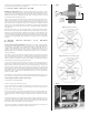
Remove the strap ring, retaining nut and one washer from the end of the jack.
There should still be one star locking washer, one flat washer and a nut
remaining on the jack. Bring the jack down through the soundhole into the
body and insert it into the pre-drilled hole in the tail block. Using the internal
nut (be sure to include the flat and star washers), set the proper depth that
will allow the entire smaller threaded section to protrude from the instrument
(see figure 2).
With the jack in place, lay the remaining washer over the threads and attach
the external retaining nut until it’s tight. Finish by attaching the strap ring (it
should cover the retaining nut and washer). Asserting too much pressure may
crack the finish. Now bring the preamp into the guitar (do not adhere it yet),
connect a battery, and plug the strapjack cable into the "output" socket. Then
proceed to the appropriate iBeam installation instructions in the following
sections.
4 . i B E A M I N S T A L L A T I O N : P I N B R I D G E
G U I T A R S
4.1 General positioning guidelines: The iBeam is a highly sensitive pickup;
therefore, placement and the unique characteristics of the instrument are
critical factors in producing the outstanding results of which the iBeam is
capable. A few millimeters in any direction can have profound effects on the
quality of the sound. Because every guitar is different, we can tell you
approximately where the pickup should be placed, but we can not provide an
exact specification.
The iBeam is designed to attach to the bridge plate directly under the saddle
line and generally parallel to the saddle, with the attached peel-and-stick
adhesive. Good results should be consistently had by attaching the pickup as
shown in figure 3. However, because every guitar is unique, you may be
rewarded by searching for the optimum location.
In general, placing the iBeam directly under the saddle will provide the
greatest sense of immediacy, impact, snap and “string” sound. Offsetting the
pickup either toward the sound hole or toward the bridge pins in the area
shown in figure 4 will increase the amount of “body” in the sound and
generally have a more mellow and homogeneous tone with less midrange. We
have often achieved our very best results by placing the pickup as close to the
string ball-ends as is practical and offsetting it about 1 to 2 mm toward the
treble side of the saddle.
An alternative location that has often worked well, provided the x-braces are
wide enough, is to offset the pickup toward the front edge of the bridge plate.
4.2 Pin bridge installation (initial placement):
1. Assemble the mounting fixture.
2. Remove the strings from the pin holes.
3. Reach inside the hole and feel around under the bridge to be sure the
bridge plate is free from debris and obstructions. If you are unsure, stick a
mirror inside to inspect this area.
4. Place the stationary rod of the mounting fixture in the high-E bridge pin
hole and adjust the movable rod laterally in the slot until it drops into the low-
E bridge pin hole as shown in figure 5. Tighten the nut to secure the movable
rod.
5. Place the adhesive dots on the fixture over the saddle (see figure 5), one on
each side of the big slot. Remove the adhesive backing from the dots and
position the iBeam over the fixture in the desired location. Stick the iBeam to
the adhesive dots on the fixture as shown in figure 6.
6. Remove the fixture and iBeam together from the bridge and remove the
adhesive backing from the bottom surface of the iBeam.
fig. 3: primary location
fig. 4: alternative mounting area
fig. 5
tail
block
smaller
threaded
section
protrudes
fig. 2