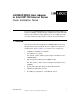
® LSI22902/22903 Host Adapter to Intel ISP1100 Internet Server Quick Installation Guide The LSI Logic LSI22902/22903 PCI to Dual Channel Ultra2 SCSI Low Profile Host Adapter is ideally suited for installation into the Intel ISP1100 Internet Server Platform. In this application, the host adapter provides one internal LVD only channel and one LVD or SE external channel. 1 Overview This document describes installing the LSI22902/22903 into the Intel ISP1100 Internet Server Platform.
Figure 1 LSI22902 Host Adapter Kit 2 Installation The installation process contains the following four major sections: 2 • Section 2.1, “Setting up the Installation” • Section 2.2, “Installing the Host Adapter Board” • Section 2.3, “Installing New Drives” • Section 2.
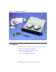
2.1 Setting up the Installation Important: Make sure the ISP1100 server is turned off and is not plugged into an electrical outlet. Take all precautions to minimize ESD. A ground strap is recommended. Step 1. Identify the parts listed below on the LSI22902/22903. Refer to Figure 2 for a photograph of the board. • Internal Channel B, 68-pin HD connector, J4. • Hard drive activity LED connector, J3. • External Channel A, VHDCI 68-pin connector, J2.
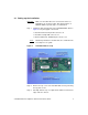
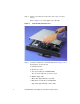
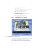
Step 4. Lift the cover using the notch in the front of the cover and remove. Refer to Figure 3 for a photograph of the ISP1100. Figure 3 Intel ISP1100 Internet Server Step 5. Locate the components of the ISP1100. Refer to Figure 4 for a photograph of an opened unit. a. Retention bracket. b. PCI bus riser card. c. Area for mounting the LSI22902/22903. The slot on the right side of the riser card. d. Slimline floppy cable. White cable approximately 1 inch wide. e. IDE cables for hard drives and CD-ROM.
f. Slimline floppy and CD-ROM assembly. g. Two hard drive bays. The ISP1100 is provided with a floppy cable for hard drives, but no drives are installed or included. h. IDE cable with hard drive connectors. The cables are routed under the drive bays and the CD-ROM/floppy assembly. i. SCSI hard drive activity LED connector . J11 on the mainboard. Figure 4 Intel ISP1100 Server, Cover Removed 2.
Refer to Figure 5. Step 2. On the back of the chassis, remove the two screws holding the expansion bays retention bracket. Step 3. Remove the retention bracket and the expansion slot cover. Figure 5 PCI Slot Location You can use one of two methods to install the SCSI card in the ISP1100. Both methods install the board in the same location but use a different sequence of steps. You might want to review both methods to see which you prefer.
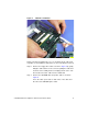
Step 1. Attach the hard drive LED cable to the SCSI host adapter card. Use either pin pairs 1-2 or 3-4, as shown in the inset in Figure 6. Step 2. With the host adapter board bracket facing the rear of the computer, insert the host adapter card in the expansion slot by carefully pressing the PCI bus edge connector into the PCI slot. The SCSI card aligns itself properly to the PCI slot if the card guide bracket is in the proper position.
2.2.2 LSI22902 Installation Method 2 Method 2 is different from the first method in that you remove the riser card from the ISP1100 to insert the LSI22902/22903, rather than doing it in place as in Method 1. Refer to Figure 7 for a photograph showing the host adapter installed in the riser card. Step 1. Attach the hard drive LED cable to the SCSI host adapter card. Use either pin pairs 1-2 or 3-4, as shown in the inset in Figure 7. Step 2. Gently remove the riser card from the server board connector.
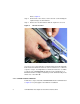
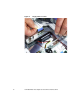
Figure 7 Method 2 Installation At this point in the installation process, you should be at the same point, regardless of the installation method chosen. Proceed with the next step. Step 6. Remove the floppy drive cable as shown in Figure 8 by gently lifting the cable retainer on the connector, pulling the cable from under the fan assembly bracket, and laying it back to the side. Do not disconnect this cable from the mainboard. Step 7. Remove the CD-ROM cable and power cable as shown in Figure 9.
Figure 8 10 Floppy Cable Location LSI22902/22903 Host Adapter to Intel ISP1100 Internet Server
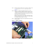
Figure 9 CD-ROM and Power Cables 2.3 Installing New Drives This section of the procedure describes installing the proper SCSI hard drives, as well as a CD-ROM drive and floppy drive, in the ISP1100. It also includes removing the existing IDE hard drives shipped with the unit. Step 1. Remove the slimline CD-ROM and floppy assembly from the ISP1100 by removing the three screws holding the assembly to the chassis. Refer to Figure 10 for a photograph of the Slimline CD-ROM/floppy assembly.
Figure 10 CD-ROM/Floppy Assembly Step 2. Remove the two hard drive bays by lifting the back of the bay until the bay clears the two snaptop standoffs and remove. Refer to Figure 11 for a photograph of this step. Step 3. Mount the two LVD SCSI hard drives in the bays according to the installation instructions from the original equipment manufacturer. Refer to the inset photograph in Figure 11.
Figure 11 Note: Removing the Hard Drive Bays Each device on the SCSI bus, in this case, the host adapter and hard drives, must have a unique SCSI ID. SCSI ID 7 is the default host adapter setting. See the documentation for your hard drives for assistance in determining and if necessary, changing, the device’s SCSI ID. SCSI ID 0 and 1 are recommended for the two internal hard drives. For further information about setting SCSI IDs, contact LSI Logic Technical Support at 719-533-7230. Step 4.
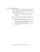
Figure 12 Removing the IDE Cable Step 5. Pull the Slimline floppy cable up and lay it out of the way temporarily. Step 6. Attach the preformed 68-pin LVD SCSI cable to the host adapter board. Step 7. Route the cable along the side of the chassis under the fan assembly bracket and lay the cable flat under the CD-ROM and drive bay positions. The LVD terminator is attached to the end of the SCSI cable and should rest between the two drive bays. Step 8. Lay the floppy cable back on top of the SCSI cable.
Figure 13 SCSI Cable Routing Step 9. Install both drive bays by positioning the front tabs in their respective positions with the rear of the bay over the chassis snaptop standoffs. Step 10. Firmly press down on the rear of the bay until the bay “snaps” securely into position on the standoffs. Step 11. Attach the SCSI and power cable for each drive. The SCSI cable terminator should position itself between the two drive bays. Refer to Figure 14 for a photograph showing drive bay installation.
Figure 14 Drive Bay Installation Step 12. Reinstall the CD-ROM and floppy drives. Use the three mounting screws and attach the CD-ROM/floppy devices to the chassis, taking care to not overtighten the mounting screws. Overtigntening cause warp in the ISP1100 chassis. Step 13. Connect the IDE secondary channel cable and the power cable for the CD-ROM. Step 14. Connect the floppy cable. Refer to Figure 15 for a photograph of the CD-ROM and floppy drive installation.
Figure 15 CD-ROM and Floppy Installation 2.4 Completing the Installation Step 1. Attach the loose end of the hard drive LED cable to the server board SCSI LED connector, J11. Refer to Figure 16 on the next page for a photograph showing the LED cable attachment. Step 2. Position the top cover of the ISP1100 and secure with the mounting screw. The Intel ISP1100 Internet Server is now ready to be mounted into a rack mount system and is ready for software installation.
Figure 16 18 Attaching the Hard Drive LED Activity Cable LSI22902/22903 Host Adapter to Intel ISP1100 Internet Server
Notes LSI22902/22903 Host Adapter to Intel ISP1100 Internet Server 19
Headquarters LSI Logic Corporation North American Headquarters Milpitas CA Tel: 408.433.8000 Fax: 408.433.8989 LSI Logic Europe Ltd European Headquarters Bracknell England Tel: 44.1344.426544 Fax: 44.1344.481039 LSI Logic K.K. Headquarters Tokyo Japan Tel: 81.3.5463.7821 Fax: 81.3.5463.7820 To receive product literature, visit us at http://www.lsilogic.com. ISO 9000 Certified The LSI Logic logo design is a registered trademark or trademark of LSI Logic Corporation.