72-Inch Cabinet Site Preparation and Installation Guide AA1167-E1, First Edition
This document contains proprietary information of LSI Logic Corporation. The information contained herein is not to be used by or disclosed to third parties without the express written permission of an officer of LSI Logic Corporation. Any product(s) described herein is/are a licensed product of LSI Logic Corporation. Document AA1167-E1, First Edition.
Federal Communications Commission (FCC) Radio Frequency Interference Statement This equipment has been tested and found to comply with the limits for a Class A digital device, pursuant to Part 15 of the FCC Rules. These limits are designed to provide reasonable protection against harmful interference in a commercial installation.
Revision Record Revision Date First Edition July 2001 Affected Pages/Remarks First Printing Part Number: AA1167-E1 ii 72-Inch Cabinet Site Preparation and Installation Guide
Contents About this Site Preparation Guide .................................................................................................. 1 Customer Responsibilities ......................................................................................................... 1 Cabinet Features .............................................................................................................................. 2 Reference Documentation ...............................................................
List of Figures 1 72-inch Cabinet .............................................................................................................................2 2 72-inch Cabinet with Command and Drive Modules ................................................................3 3 Cabinet Dimensions ......................................................................................................................6 4 Cabinet Area Requirements ..................................................................
List of Tables 1 Cabinet, Crate, and Module Weights .......................................................................................... 7 2 Environmental Requirements ...................................................................................................... 9 3 Power Requirements ..................................................................................................................
vi 72-Inch Cabinet Site Preparation and Installation Guide
. . . . . . . . . . . . . . . . . . . . . . . . . . . . . . . . . . . . . . . . . . . . . . . . . . About this Site Preparation Guide About this Site Preparation Guide This document is intended for service technicians. It contains site preparation requirements and instructions for installing a 72-inch cabinet. This document also provides instructions for transporting the cabinet to another location.
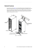
.............................................................................. Cabinet Features The rackmount cabinet (Figure 1) has a detachable back door and standard Electronic Industry Association (EIA) rails, which provide mounting holes for installing 19-inch wide devices. The cabinet has four roller casters and four adjustable guides for moving and leveling the cabinet during installation and relocation.
. . . . . . . . . . . . . . . . . . . . . . . . . . . . . . . . . . . . . . . . . . . . . . . . . . . . . . . . . . . . . . . Cabinet Features Depending upon performance, capacity, and availability requirements, you can customize the cabinet to meet your data storage needs. The cabinet contains two AC distribution boxes and can support up to twelve command modules and drive modules.
.............................................................................. Reference Documentation The following documents contain additional information on command and drive modules, their installation, and cabling schemes. These documents are listed chronological order from newest to oldest, based on the month and year they were released.
. . . . . . . . . . . . . . . . . . . . . . . . . . . . . . . . . . . . . . . . . . . . . . . . . . . . . . . . . . . . . . . Cabinet Features • MetaStor CM2000 Command Module Installation Guide, J90981S-0999, Revision B, Third Printing (March 2000) – provides information and step-by-step instructions for installing CM2000 Command Modules containing 4766 controllers and running SYMplicity Storage Manager (6.x) or SANtricity Storage Manager (7.00, 7.01, or 7.
.............................................................................. Dimensions and Weights Dimensions The cabinet has the following dimensions (Figure 3), excluding the removable stability foot: • • • Height:183 cm (72 in.) Width: 56 cm (22 in.) Depth: 91 cm (36 in.
. . . . . . . . . . . . . . . . . . . . . . . . . . . . . . . . . . . . . . . . . . . . . . . . . . . . . . . . . Dimensions and Weights Weights The total weight depends on the type and quantity of modules installed in the 72-inch cabinet. Table 1 lists the overall weight of the cabinet, plus the maximum weights for the command and drive modules. You can use these weights to estimate the total weight of your system, based on the number of devices installed in the cabinet.
.............................................................................. Area Requirements The floor area at the installation site must provide: • Enough stability to support the weight of the 72-inch cabinet and installed devices (Table 1 on page 7) • • Sufficient space to install and service the cabinet and components (Figure 4) Sufficient ventilation to provide a free flow of air to the cabinet. Air flow in the cabinet is from the front to back.
. . . . . . . . . . . . . . . . . . . . . . . . . . . . . . . . . . . . . . . . . . . . . . . . . . . . . . Environmental Requirements Environmental Requirements Table 2 Environmental Requirements Environment Altitude Requirements Operating Range Storage Range Transit Range Below Sea Level 30.5 m (100 ft.) 30.5 m (100 ft.) 30.5 m (100 ft.) Above Sea Level 3000 m (9840 ft.) 3000 m (9840 ft.) 12,000 m (40,000 ft.
.............................................................................. Power Requirements Table 3 Power Requirements Unit/Component Requirements Domestic International AC Power 250 VAC, 30 A 230 VAC, 32 A AC Plug NEMA L6-30P, locking plug IEC 309 locking plug Receptacle 6-30R, receptacle IEC 309 receptacle Circuit Breaker 20 A Voltage Range 180 to 257 VAC Frequency 49 to 50.5 Hz or 59 to 60.
. . . . . . . . . . . . . . . . . . . . . . . . . . . . . . . . . . . . . . . . . . . . . . . . . . . . . . . . . . . . Power Requirements AC Power Distribution The 72-inch cabinet has two identical AC power boxes (Figure 5).
.............................................................................. Power Box Cables Each AC box outlet supports on ladder-attach power cable (Figure 6) that you can connect to a maximum of six devices. You may connect up to twelve 220/230 VAC devices to each AC box for a maximum of twenty-four power attachments inside the cabinet. Although the cabinet may not be fully populated when shipped, the 72-inch cabinet is shipped with four, ladder-attach cables for easier expansion in the future.
. . . . . . . . . . . . . . . . . . . . . . . . . . . . . . . . . . . . . . . . . . . . . . . . . . . . . . . . . . . . Power Requirements Power Cords and Receptacles The cabinet is shipped with two power cords: one for domestic use, the other for international use. Each cord connects to an independent 24 A circuit breaker and an AC distribution box. The AC distribution box has two outlets for connecting the power cords from devices installed in the cabinet. Figure 7 shows these receptacles.
.............................................................................. Site Wiring and Power Considerations The cabinet’s AC distribution boxes use common industrial wiring. Consider the following site wiring and power source requirements: • AC power source. The AC power source must provide the correct voltage, current, and frequency specified on the manufacturer’s name plate. • Earth ground. You must have an earth grounding conductor to the cabinet’s power receptacles. • Circuit overloading.
. . . . . . . . . . . . . . . . . . . . . . . . . . . . . . . . . . . . . . . . . . . . . . . . . . . . . . . . . . .
.............................................................................. Unpacking and Moving the Cabinet WARNING Risk of bodily injury! The cabinet can weigh up to 636 kg (1420 lb) fully loaded. Do not attempt to move the cabinet without a forklift or sufficient help from others. Always push the cabinet from the front to prevent it from tipping over (Figure 10).
. . . . . . . . . . . . . . . . . . . . . . . . . . . . . . . . . . . . . . . . . . . . . . . . . . . . . . . . . . .
..............................................................................
. . . . . . . . . . . . . . . . . . . . . . . . . . . . . . . . . . . . . . . . . . . . . . . . . . . . . . . . . . .
.............................................................................. Installing the Cabinet The installation tasks you must perform depends on how you ordered the 72-inch cabinet and its associated modules. In most cases, you will need to do some or all of the following: 1 Check the shipping contents list to make sure all equipment arrived at the site. 2 Move the cabinet to its final location. Once it is in position, lower the levelling glides and level the unit as necessary.
. . . . . . . . . . . . . . . . . . . . . . . . . . . . . . . . . . . . . . . . . . . . . . . . . . . . . . . . Transportation Instructions Transportation Instructions WARNING Risk of bodily harm. Failure to follow this procedure could result in a cabinet becoming very unstable up/down inclines or over uneven surfaces. To maximize stability during the transportation of a 72-inch cabinet, the center of gravity for the cabinet must be as close to the base as possible.
..............................................................................