Command Module and Drive Module Site Preparation Guide AP1172-E1, First Edition
Proprietary Rights Notice This document contains proprietary information of LSI Logic Corporation. The information contained herein is not to be used by or disclosed to third parties without the express written permission of an officer of LSI Logic Corporation. Any product(s) described herein is/are a licensed product of LSI Logic Corporation. Document Description Document AP1172-E1, First Edition.
Regulatory Compliance Statements FCC Radio Frequency Interference Statement This equipment has been tested and found to comply with the limits for a Class A digital device, pursuant to Part 15 of the Federal Communications Commission (FCC) Rules. These limits are designed to provide reasonable protection against harmful interference in a commercial installation.
Revision Record Edition or Revision Date Affected Pages or Remarks First Edition September 2002 New Book.
Contents Chapter 1: 72-INCH CABINET SITE PREPARATION Cabinet Features ........................................................................................................................... 1-2 Area Requirements ....................................................................................................................... 1-4 Weights .................................................................................................................................... 1-5 Dimensions.................
Chapter 3: DRIVE MODULE SITE PREPARATION Area Requirements....................................................................................................................... 3-2 Weights.................................................................................................................................... 3-2 Dimensions ............................................................................................................................. 3-4 Shipping Carton Dimensions ..................
List of Figures Chapter 1: 72-INCH CABINET SITE PREPARATION Figure 1-1. 72-inch Cabinet ........................................................................................................ 1-2 Figure 1-2. Cabinet Area Requirements ..................................................................................... 1-4 Figure 1-3. Cabinet Dimensions ................................................................................................. 1-6 Figure 1-4. Cabinet AC Distribution ..................
vi Command Module and Drive Module Site Preparation Guide
List of Tables Chapter 1: 72-INCH CABINET SITE PREPARATION Table 1-1. Cabinet, Crate, and Module Weights ....................................................................... 1-5 Table 1-2. Cabinet Environmental Requirements ..................................................................... 1-7 Table 1-3. Power Requirements ................................................................................................. 1-8 Chapter 2: COMMAND MODULE SITE PREPARATION Table 2-1.
Chapter 4: ARRAY MODULE SITE PREPARATION Table 4-1. E2400 10x Array Module Weight ............................................................................. 4-2 Table 4-2. E2400 14x Array Module Weight ............................................................................. 4-3 Table 4-3. Array Module Shipping Carton Dimensions ........................................................... 4-5 Table 4-4. Array Module Environmental Requirements ..........................................................
Chapter 1 72-Inch Cabinet Site Preparation This chapter contains essential site preparation information for the 72-inch cabinet that you will use to determine installation, service, and operating floor space requirements; heating and air conditioning specifications; and voltage and power requirements.
72-Inch Cabinet Site Preparation . . . . . . . . . . . . . . . . . . . . . . . . . . . . . . . . . . . . . . . . . . . . . . . . . . . Cabinet Features The rackmount cabinet (Figure 1-1) has a detachable back door and standard Electronic Industry Association (EIA) rails, which provide mounting holes for installing 19-inch wide devices. The cabinet has four roller casters and four adjustable guides (located beneath the cabinet) for moving and leveling the cabinet during installation and relocation.
. . . . . . . . . . . . . . . . . . . . . . . . . . . . . . . . . . . . . . . . . . . . . . . . . . . . . . . . . . . . . . . Cabinet Features You can customize the cabinet to meet your data storage needs, based on performance, capacity, and availability requirements. The cabinet contains two AC power distribution boxes and can support a combination of twelve modules. The cabinet will ship with a maximum of three command modules installed.
72-Inch Cabinet Site Preparation . . . . . . . . . . . . . . . . . . . . . . . . . . . . . . . . . . . . . . . . . . . . . . . . . . . Area Requirements The floor area at the installation site must provide enough stability to support the weight of the cabinet and installed devices, sufficient space to install and service the cabinet and components, and sufficient ventilation to provide a free flow of air to the cabinet. Airflow in the cabinet is from the front to back. See Figure 1-2 for more information.
. . . . . . . . . . . . . . . . . . . . . . . . . . . . . . . . . . . . . . . . . . . . . . . . . . . . . . . . . . . . . . Area Requirements Weights The total weight depends on the type and quantity of modules installed in the cabinet. Table 1-1 lists the overall weight of the cabinet, plus the maximum weight for each module. Use these weights to estimate the total weight of your system, based on the number of modules installed in the cabinet.
72-Inch Cabinet Site Preparation . . . . . . . . . . . . . . . . . . . . . . . . . . . . . . . . . . . . . . . . . . . . . . . . . . . Dimensions The cabinet has the following dimensions (Figure 1-3), excluding the removable stability foot: • • • Height – 183 cm (72 in.) Width – 56 cm (22 in.) Depth – 91 cm (36 in.
. . . . . . . . . . . . . . . . . . . . . . . . . . . . . . . . . . . . . . . . . . . . . . . . . . . . . . Environmental Requirements Environmental Requirements The cabinet is designed to operate in the environment defined in Table 1-2. Table 1-2 Cabinet Environmental Requirements Environment Altitude Requirements Operating Range Storage Range Transit Range Below Sea Level 30.5 m (100 ft.) 30.5 m (100 ft.) 30.5 m (100 ft.) Above Sea Level 3048 m (10,000 ft.) 3048 m (10,000 ft.
72-Inch Cabinet Site Preparation . . . . . . . . . . . . . . . . . . . . . . . . . . . . . . . . . . . . . . . . . . . . . . . . . . . Power Requirements This section provides information regarding power requirements, AC power distribution box specifications, ladder cord and power cord routing instructions, and site wiring conditions. The AC power source must provide the correct voltage, current, and frequency specified on the manufacturer’s nameplate.
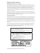
. . . . . . . . . . . . . . . . . . . . . . . . . . . . . . . . . . . . . . . . . . . . . . . . . . . . . . . . . . . . Power Requirements AC Power Distribution Boxes The cabinet has two identical AC power distribution boxes with two separate power cords (Figure 1-4).
72-Inch Cabinet Site Preparation . . . . . . . . . . . . . . . . . . . . . . . . . . . . . . . . . . . . . . . . . . . . . . . . . . . Ladder Cords Each AC power distribution box outlet supports one ladder cord (Figure 1-5) that you can connect to a maximum of six modules. You may connect up to twelve 220/230 VAC modules to each AC power distribution box for a maximum of twenty-four power attachments inside the cabinet.
. . . . . . . . . . . . . . . . . . . . . . . . . . . . . . . . . . . . . . . . . . . . . . . . . . . . . . . . . . . . Power Requirements Power Cords and Receptacles The cabinet is shipped with two power cords: one for domestic (inside USA) use, the other for international (outside USA) use. Each power cord connects to an independent 25 A circuit breaker and an AC power distribution box.
72-Inch Cabinet Site Preparation . . . . . . . . . . . . . . . . . . . . . . . . . . . . . . . . . . . . . . . . . . . . . . . . . . . Site Wiring The cabinet’s AC power distribution boxes use common industrial wiring. Consider the following information when preparing the cabinet installation site: • AC power source – The AC power source must provide the correct voltage, current, and frequency specified on the manufacturer’s nameplate.
Chapter 2 Command Module Site Preparation This chapter provides technical specifications and information you will need to prepare a site before installing the E4400, E4600, and the E5600 command modules. This chapter provides information you will use to determine installation, service, and operating floor space requirements; heating and air conditioning specifications; voltage and power requirements; and adapter, module, transceiver, and cabling specifications for interface connectors.
Command Module Site Preparation . . . . . . . . . . . . . . . . . . . . . . . . . . . . . . . . . . . . . . . . . . . . . . . . . Area Requirements The floor space at the installation site must provide enough strength to support the weight of the command module and associated equipment, sufficient space to install, operate, and service the command module, and sufficient ventilation to provide a free flow of air to the unit.
. . . . . . . . . . . . . . . . . . . . . . . . . . . . . . . . . . . . . . . . . . . . . . . . . . . . . . . . . . . . . . Area Requirements Table 2-2 E4600 Command Module Weight Maximum1 Empty Unit3 Unit Weight Shipping2 Weight Weight Shipping2 Weight Rackmount Command Module 43.99 kg (97.0 lb) 57.2 kg (125.9 lb) 18.07 kg (39.84 lb) 30.8 kg (67.8 lb) Battery 10.89 kg (24.0 lb) 12.97 kg (28.6 lb) Controller 3.0 kg (6.6 lb) 5.0 kg (11.0 lb) Controller Fan 0.9 kg (1.9 lb) 2.3 kg (5.
Command Module Site Preparation . . . . . . . . . . . . . . . . . . . . . . . . . . . . . . . . . . . . . . . . . . . . . . . . . Dimensions Command module dimensions are the same for each model (Figure 2-1). 44.5 cm (17.5 in.) Rackmount 17.5 cm (6.9 in.) 61.0 cm (24.0 in.) 48.2 cm (19.0 in.) 2.0 cm (0.8 in.) Figure 2-1 Command Module Dimensions Shipping Carton Dimensions Shipping carton dimensions include the height of the pallet and are the same for all models (Table 2-4).
. . . . . . . . . . . . . . . . . . . . . . . . . . . . . . . . . . . . . . . . . . . . . . . . . . . . . . . . . . . . . . Area Requirements Airflow For proper ventilation, allow at least 2 feet of clearance in front of and behind the command module (Figure 2-2).
Command Module Site Preparation . . . . . . . . . . . . . . . . . . . . . . . . . . . . . . . . . . . . . . . . . . . . . . . . . Environmental Requirements The command module is designed to operate in the environment defined in Table 2-5 and Table 2-6.
. . . . . . . . . . . . . . . . . . . . . . . . . . . . . . . . . . . . . . . . . . . . . . . . . . . . . . Environmental Requirements Table 2-6 Command Module Heat Dissipation Model Heat Dissipation E4400 657.5 Btu/hr (0.1925 kVA or 192.5 W) E4600 790.0 Btu/hr (0.2333 kVA or 231.0 W) E5600 786.6 Btu/hr (0.2300 kVA or 230.
Command Module Site Preparation . . . . . . . . . . . . . . . . . . . . . . . . . . . . . . . . . . . . . . . . . . . . . . . . . Power Requirements This section provides information regarding command module AC power requirements, power cord routing instructions, and site wiring conditions. The AC power source must provide the correct voltage, current, and frequency specified on the manufacturer’s nameplate.
. . . . . . . . . . . . . . . . . . . . . . . . . . . . . . . . . . . . . . . . . . . . . . . . . . . . . . . . . . . .
Command Module Site Preparation . . . . . . . . . . . . . . . . . . . . . . . . . . . . . . . . . . . . . . . . . . . . . . . . .
. . . . . . . . . . . . . . . . . . . . . . . . . . . . . . . . . . . . . . . . . . . . . . . . . . . . . . . . . . . . Power Requirements Site Wiring The command module uses wide-ranging, redundant power supplies that automatically accommodate voltages to the AC power source. The power supplies operate at a range between 90 VAC and 264 VAC, and at a minimum frequency of 50 Hz and a maximum frequency of 60 Hz.
Command Module Site Preparation . . . . . . . . . . . . . . . . . . . . . . . . . . . . . . . . . . . . . . . . . . . . . . . . . Interface Cables and Connections This section provides information about command module interface cables, such as GBIC minihubs and SFP transceivers, and their appropriate connections. See Figure 2-5 and Figure 2-6 on page 2-14 for command module interface connector examples.
. . . . . . . . . . . . . . . . . . . . . . . . . . . . . . . . . . . . . . . . . . . . . . . . . . Interface Cables and Connections If you order optical GBIC connectors, you will need fiber optic cable. If you order copper GBIC minihubs or DB-9 minihubs, you will need copper fiber cable. Refer to Table 2-8 for types and cable lengths available from your local dealer.
Command Module Site Preparation . . . . . . . . . . . . . . . . . . . . . . . . . . . . . . . . . . . . . . . . . . . . . . . . . E4600 and E5600 Command Modules The E4600 and E5600 command modules support fiber optic connections to both hosts and drive modules. Up to four host minihubs and four drive minihubs can be installed in a command module. Each Small Form-factor Pluggable (SFP) minihub has two connectors, allowing a maximum of sixteen connections.
. . . . . . . . . . . . . . . . . . . . . . . . . . . . . . . . . . . . . . . . . . . . . . . . . .
Command Module Site Preparation . . . . . . . . . . . . . . . . . . . . . . . . . . . . . . . . . . . . . . . . . . . . . . . . .
Chapter 3 Drive Module Site Preparation This chapter provides technical specifications and information you will need to prepare a site before installing a FC-1 10x, FC-1 14x, or FC-2 14x drive module. This chapter provides information you will use to determine installation, service, and operating floor space requirements; heating and air conditioning specifications; voltage and power requirements; and adapter, module, transceiver, and cabling specifications for interface connectors.
Drive Module Site Preparation. . . . . . . . . . . . . . . . . . . . . . . . . . . . . . . . . . . . . . . . . . . . . . . . . . . . . . Area Requirements The floor space at the installation site must provide enough strength to support the weight of the drive module and associated equipment, sufficient space to install, operate, and service the drive module, and sufficient ventilation to provide a free flow of air to the unit.
. . . . . . . . . . . . . . . . . . . . . . . . . . . . . . . . . . . . . . . . . . . . . . . . . . . . . . . . . . . . . . Area Requirements Table 3-2 FC-1 14x Drive Module Weight Weight Maximum Unit Shipping3 Drive Module Rackmount Low Profile (LP) drives 40.95 kg (90.5 lb)1 47.25 kg (105.0 lb) Drive Module Drive-ready Rackmount LP drives 30.5 kg (66.4 lb)2 37.44 kg (83.2 lb) Unit LP Drive, 18 GB or 36 GB 1.0 kg (2.2 lb) LP Drive, Blank Canisters 0.32 kg (0.72 lb) ESM 1.67 kg (3.
Drive Module Site Preparation. . . . . . . . . . . . . . . . . . . . . . . . . . . . . . . . . . . . . . . . . . . . . . . . . . . . . . Dimensions Drive module dimensions for each model differ slightly. See Figure 3-1 and Figure 3-2 for model descriptions. 16.6 cm (6.5 in.) 52.7 cm (20.7 in.) 56.0 cm (22.0 in.) 44.7 cm (17.6 in.) 12.9 cm (5.08 in.) 13.18 cm (5.2 in.) 55.91 cm (22.0 in.) 48.0 cm (18.9 in.) 1.59 cm (0.625 in.
. . . . . . . . . . . . . . . . . . . . . . . . . . . . . . . . . . . . . . . . . . . . . . . . . . . . . . . . . . . . . . Area Requirements 44.70 cm (17.60 in) 59.74 cm (23.52 in.) 12.9 cm (5.08 in.) 13.23 cm (5.21 in.) 56.13 cm (22.1 in.) 48.18 cm (18.97 in.) 3.63 cm (1.43 in.) Figure 3-2 FC-1 14x and FC-2 14x Drive Module Dimensions Shipping Carton Dimensions Shipping carton dimensions include the height of the pallet (Table 3-4).
Drive Module Site Preparation. . . . . . . . . . . . . . . . . . . . . . . . . . . . . . . . . . . . . . . . . . . . . . . . . . . . . . Airflow For proper ventilation, allow at least 2 feet of clearance in front of and behind the drive module (Figure 3-3).
. . . . . . . . . . . . . . . . . . . . . . . . . . . . . . . . . . . . . . . . . . . . . . . . . . . . . . Environmental Requirements Environmental Requirements The drive module is designed to operate in the environment defined in Table 3-5 and Table 3-6 on page 3-7.
Drive Module Site Preparation. . . . . . . . . . . . . . . . . . . . . . . . . . . . . . . . . . . . . . . . . . . . . . . . . . . . . . Power Requirements This section provides information regarding drive module AC power requirements, power cord routing instructions, and site wiring conditions. The AC power source must provide the correct voltage, current, and frequency specified on the manufacturer’s nameplate.
. . . . . . . . . . . . . . . . . . . . . . . . . . . . . . . . . . . . . . . . . . . . . . . . . . . . . . . . . . . . Power Requirements Table 3-9 Item Circuit Breaker FC-2 14x Drive Module Power Requirements Unit of Measure Slow-blow Fuse 10 A per Power Supply Low Range High Range 90 to 136 VAC 198 to 264 VAC 50 to 60 Hz 50 to 60 Hz Idle Current 2.93 A1 1.27 A2 Maximum Operating Current 3.18 A1 1.37 A2 Maximum Surge Current 5.85 A1 2.
Drive Module Site Preparation. . . . . . . . . . . . . . . . . . . . . . . . . . . . . . . . . . . . . . . . . . . . . . . . . . . . . .
. . . . . . . . . . . . . . . . . . . . . . . . . . . . . . . . . . . . . . . . . . . . . . . . . . . . . . . . . . . .
Drive Module Site Preparation. . . . . . . . . . . . . . . . . . . . . . . . . . . . . . . . . . . . . . . . . . . . . . . . . . . . . . Site Wiring The drive modules use wide-ranging, redundant power supplies that automatically accommodate voltages to the AC power source. The power supplies operate at a range between 90 VAC and 264 VAC, and at a minimum frequency of 50 Hz and a maximum frequency of 60 Hz.
. . . . . . . . . . . . . . . . . . . . . . . . . . . . . . . . . . . . . . . . . . . . . . . . . . Interface Cables and Connections Interface Cables and Connections This section provides information about drive module interface cables, such as GBIC modules and SFP transceivers, and their appropriate connections. FC-1 10x and FC-1 14x Drive Modules The FC-1 10x and FC-1 14x drive modules support Fibre Channel connections to command modules. Each have four GBIC modules; two on each ESM (Figure 3-6).
Drive Module Site Preparation. . . . . . . . . . . . . . . . . . . . . . . . . . . . . . . . . . . . . . . . . . . . . . . . . . . . . . If you order optical GBIC modules, you will need fiber optic cable. If you order copper GBIC modules, you will need copper fiber cable. Refer to Table 3-10 for types and cable lengths available from your local dealer.
. . . . . . . . . . . . . . . . . . . . . . . . . . . . . . . . . . . . . . . . . . . . . . . . . . Interface Cables and Connections FC-2 14x Drive Module The FC-2 14x drive module supports Fibre Channel connections to command modules. The drive module ships with two ESMs, and each has connectors for two optical Small Form-factor Pluggable (SFP) transceivers (Figure 3-7).
Drive Module Site Preparation. . . . . . . . . . . . . . . . . . . . . . . . . . . . . . . . . . . . . . . . . . . . . . . . . . . . . .
Chapter 4 Array Module Site Preparation This chapter provides technical specifications and information you will need to prepare a site before installing the E2400 10x and E2400 14x array modules. This chapter provides information you will use to determine installation, service, and operating floor space requirements; heating and air conditioning specifications; voltage and power requirements; and adapter, module, transceiver, and cabling specifications for interface connectors.
Array Module Site Preparation . . . . . . . . . . . . . . . . . . . . . . . . . . . . . . . . . . . . . . . . . . . . . . . . . . . . . Area Requirements The floor space at the installation site must provide enough strength to support the weight of the array module and associated equipment, sufficient space to install, operate, and service the array module, and sufficient ventilation to provide a free flow of air to the unit.
. . . . . . . . . . . . . . . . . . . . . . . . . . . . . . . . . . . . . . . . . . . . . . . . . . . . . . . . . . . . . . Area Requirements Table 4-2 E2400 14x Array Module Weight Weight Maximum Unit1 Empty Unit2 Shipping3 Array Module Deskside, Low Profile (LP) drives, 18 GB or 36 GB 52.84 kg (116.5 lb) 27.0 kg (59.54 lb) 59.0 kg (130.1 lb) Array Module Rackmount, LP drives, 18 GB or 36 GB 40.95 kg (90.5 lb) 15.21 kg (33.54 lb) 47.25 kg (105.0 lb) LP Drive, 18 GB or 36 GB 1.06 kg (2.
Array Module Site Preparation . . . . . . . . . . . . . . . . . . . . . . . . . . . . . . . . . . . . . . . . . . . . . . . . . . . . . Dimensions Array module dimensions for each model differ slightly. See Figure 4-1 and Figure 4-2 for model descriptions. 16.6 cm (6.5 in.) 52.7 cm (20.7 in.) 56.0 cm (22.0 in.) 44.7 cm (17.6 in.) 12.9 cm (5.08 in.) 13.18 cm (5.2 in.) 55.91 cm (22.0 in.) 48.0 cm (18.9 in.) 1.59 cm (0.625 in.
. . . . . . . . . . . . . . . . . . . . . . . . . . . . . . . . . . . . . . . . . . . . . . . . . . . . . . . . . . . . . . Area Requirements 16.6 cm (6.5 in.) 52.7 cm (20.7 in.) 56.0 cm (22.0 in.) 44.70 cm (17.60 in.) 59.74 cm (23.52 in.) 12.9 cm (5.08 in.) 13.23 cm (5.21 in.) 56.13 cm (22.1 in.) 48.18 cm (18.97 in.) 3.63 cm (1.43 in.) Figure 4-2 E2400 14x Array Module Dimensions Shipping Carton Dimensions The shipping carton dimensions include the height of the pallet (Table 4-3).
Array Module Site Preparation . . . . . . . . . . . . . . . . . . . . . . . . . . . . . . . . . . . . . . . . . . . . . . . . . . . . . Airflow For proper ventilation, allow at least 2 feet of clearance in front of and behind the array module (Figure 4-3).
. . . . . . . . . . . . . . . . . . . . . . . . . . . . . . . . . . . . . . . . . . . . . . . . . . . . . . Environmental Requirements Environmental Requirements The array modules are designed to operate in the environment defined in Table 4-4 and Table 4-5 on page 4-7.
Array Module Site Preparation . . . . . . . . . . . . . . . . . . . . . . . . . . . . . . . . . . . . . . . . . . . . . . . . . . . . . Power Requirements This section provides information regarding array module AC power requirements, power cord routing instructions, and site wiring conditions. The AC power source must provide the correct voltage, current, and frequency specified on the manufacturer’s nameplate.
. . . . . . . . . . . . . . . . . . . . . . . . . . . . . . . . . . . . . . . . . . . . . . . . . . . . . . . . . . . . Power Requirements Power Cord Routing All modules are shipped with two AC power cords that are appropriate for use in a typical outlet in the destination country. Each power cord connects one of the power supplies in a module to an independent, external power source, such as a wall receptacle or uninterruptible power supply (UPS).
Array Module Site Preparation . . . . . . . . . . . . . . . . . . . . . . . . . . . . . . . . . . . . . . . . . . . . . . . . . . . . .
. . . . . . . . . . . . . . . . . . . . . . . . . . . . . . . . . . . . . . . . . . . . . . . . . . . . . . . . . . . . Power Requirements Site Wiring The array modules use wide-ranging, redundant power supplies that automatically accommodate voltages to the AC power source. The power supplies operate at a range between 90 VAC and 264 VAC, and at a minimum frequency of 50 Hz and a maximum frequency of 60 Hz.
Array Module Site Preparation . . . . . . . . . . . . . . . . . . . . . . . . . . . . . . . . . . . . . . . . . . . . . . . . . . . . . Interface Cables and Connections This section provides information about array module interface cables and their appropriate connections. The E2400 10x and E2400 14x array modules support Fibre Channel connections to drive modules. Each module has four GBIC connectors; two on each controller. The connectors may be fiber optic or copper (Figure 4-6).
. . . . . . . . . . . . . . . . . . . . . . . . . . . . . . . . . . . . . . . . . . . . . . . . . . Interface Cables and Connections If you order optical GBIC connectors, you will need fiber optic cable. If you order copper GBIC minihubs, you will need copper fiber cable. Refer to Table 4-8 for types and cable lengths available from your local dealer.
Array Module Site Preparation . . . . . . . . . . . . . . . . . . . . . . . . . . . . . . . . . . . . . . . . . . . . . . . . . . . . .
Index A D array module area requirements 4-2 dimensions 4-4 environmental requirements 4-7 heat dissipation 4-7 interface connections 4-12 power cord routing 4-9 power requirements 4-8 site wiring requirements 4-11 weight 4-2 data transfer rates 2-13, 3-14, 4-13 dimensions array module 4-4 cabinet 1-6 command module 2-4 drive module 3-4 drive module area requirements 3-2 dimensions 3-4 environmental requirements 3-7 heat dissipation 3-7 interface connections 3-13 power cord routing 3-9 power requirements
E4600 dimensions 2-4 environmental requirements 2-6 interface connections 2-14 power requirements 2-8 weight 2-3 E5600 dimensions 2-4 environmental requirements 2-6 interface connections 2-14 power requirements 2-8 weight 2-3 F FC-1 10x dimensions 3-4 environmental requirements 3-7 heat dissipation 3-7 interface connections 3-13 power requirements 3-8 weight 3-2 FC-1 14x dimensions 3-5 environmental requirements 3-7 heat dissipation 3-7 interface connections 3-13 power requirements 3-8 weight 3-3 FC-2 14x