MegaRAID® Express 500 Hardware Guide MAN-475 6/13/2001
© Copyright 2001 LSI Logic Corporation All rights reserved. LSI Logic Corporation 6145-D Northbelt Parkway Norcross, GA 30071 This publication contains proprietary information which is protected by copyright. No part of this publication can be reproduced, transcribed, stored in a retrieval system, translated into any language or computer language, or transmitted in any form whatsoever without the prior written consent of the publisher, LSI Logic Corporation.
Table of Contents 1 Overview .................................................. 1 Single Ended and Differential SCSI Buses....................... 2 Maximum Cable Length for SCSI Standards.................... 2 Documentation.................................................................. 3 MegaRAID Express 500 Block Diagram.......................... 4 2 Introduction to RAID................................ 5 RAID Benefits ..................................................................
Table of Contents, Continued 4 Features ................................................. 27 Hardware Requirements ................................................. 28 Configuration Features ................................................... 28 Hardware Architecture Features ..................................... 29 Array Performance Features ........................................... 29 RAID Management Features .......................................... 30 Fault Tolerance Features........................
Table of Contents, Continued 6 Hardware Installation ............................ 49 Checklist ......................................................................... 49 Installation Steps............................................................. 50 Step 1 Unpack................................................................. 51 Step 2 Power Down ........................................................ 51 Step 3 Configure Motherboard .......................................
Table of Contents, Continued 8 Troubleshooting .................................... 99 BIOS Boot Error Messages .......................................... 101 Other BIOS Error Messages ......................................... 103 DOS ASPI Driver Error Messages ............................... 104 Other Potential Problems.............................................. 105 A SCSI Cables and Connectors ............. 107 SCSI Connectors...........................................................
Preface The MegaRAID Express 500 PCI RAID Controller supports all single ended and low-voltage differential (LVD) SCSI devices on a 160M Ultra and Wide SCSI channel with data transfer rates up to 160 MB/s (Megabytes per second). This manual describes MegaRAID Express 500.
Preface, Continued Package Contents You should have received: • • • • • • • a MegaRAID Express 500 PCI RAID Controller a CD with drivers, utilities, and documentation a MegaRAID Express 500 Hardware Guide (on CD) a MegaRAID Configuration Software Guide (on CD) a MegaRAID Operating System Drivers Guide (on CD) software license agreement (on CD) a warranty registration card (on CD) Technical Support If you need help installing, configuring, or running the MegaRAID Express 500 PCI RAID Controller, call your
MegaRAID Problem Report Form Customer Information Name Company Address City/State Country email address Phone Fax Motherboard: Operating System: Op. Sys. Ver.: MegaRAID Driver Ver.
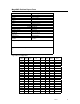
Logical Drive RAID Level Stripe Size LD20 LD21 LD22 LD23 LD24 LD25 LD26 LD27 LD28 LD29 LD30 LD31 LD32 LD33 LD34 LD35 LD36 LD37 LD38 LD39 x MegaRAID Express500 Hardware Guide Logical Drive Size Cache Policy Read Policy Write Policy # of Physical Drives
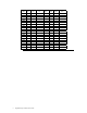
Physical Device Layout Channel 1 Target ID Device Type Logical Drive Number/ Drive Number Manufacturer/Model Number Firmware level Target ID Device Type Logical Drive Number/ Drive Number Manufacturer/Model Number Firmware level Target ID Device Type Logical Drive Number/ Drive Number Manufacturer/Model Number Firmware level Target ID Device Type Logical Drive Number/ Drive Number Manufacturer/Model Number Firmware level Target ID Device Type Logical Drive Number/ Drive Number Manufacturer/Model Number
Channel 1 Logical Drive Number/ Drive Number Manufacturer/Model Number Firmware level Target ID Device Type Logical Drive Number/ Drive Number Manufacturer/Model Number Firmware level Target ID Device Type Logical Drive Number/ Drive Number Manufacturer/Model Number Firmware level Target ID Device Type Logical Drive Number/ Drive Number Manufacturer/Model Number Firmware level Target ID Device Type Logical Drive Number/ Drive Number Manufacturer/Model Number Firmware level xii MegaRAID Express500 Har
Preface, Continued Disclaimer This manual describes the operation of the LSI Logic MegaRAID Express 500 Disk Array Controller.
FCC Regulatory Statement This device complies with Part 15 of the FCC Rules. Operation is subject to the following two conditions: (1) this device may not cause harmful interference, and (2) this device must accept any interference received, including interference that may cause undesired operation. Warning: Changes or modifications to this unit not expressly approved by the party responsible for compliance could void the user's authority to operate the equipment.
1 Overview The MegaRAID® Express 500 PCI RAID controller is a high performance intelligent PCI-to-SCSI host adapter with RAID control capabilities. The MegaRAID Express 500 provides reliability, high performance, and fault-tolerant disk subsystem management. The MegaRAID Express 500 is part of the LSI Logic Intel i960RM/RS-based MegaRAID controller family. The MegaRAID Express 500 is an entry level-to mid-range RAID controller solution.
Single Ended and Differential SCSI Buses The SCSI standard defines two electrical buses: • • a single ended bus low-voltage differential bus Maximum Cable Length for SCSI Standards Standard Single ended LVD SCSI I Fast SCSI Fast Wide SCSI Ultra SCSI Ultra SCSI Wide Ultra SCSI Wide Ultra SCSI Wide Ultra SCSI Ultra 2 SCSI Ultra 2 SCSI Wide Ultra 2 SCSI Wide Ultra 2 SCSI Ultra3 SCSI Ultra3 SCSI Wide Ultra3 SCSI Wide Ultra3 SCSI 6m 6m 6m 1.
Documentation The MegaRAID Express 500 technical documentation set includes: • • • the MegaRAID Elite 1600 Hardware Guide the MegaRAID Configuration Software Guide the MegaRAID Operating System Drivers Guide MegaRAID Configuration Hardware Guide This manual contains the RAID overview, RAID planning, and RAID system configuration information you will need first. Read the MegaRAID Express 500 Hardware Guide first.
MegaRAID Express 500 Block Diagram 4 MegaRAID Express 500 Hardware Guide
2 Introduction to RAID RAID (Redundant Array of Independent Disks) is an array of multiple independent hard disk drives that provide high performance and fault tolerance. A RAID disk subsystem improves I/O performance over a computer using only a single drive. The RAID array appears to the host computer as a single storage unit or as multiple logical units. I/O is expedited because several disks can be accessed simultaneously.
In This Chapter The following topics are discussed: Major Topic Host-based RAID solution RAID overview Subtopic Consistency check Fault tolerance Disk rebuild Hot spares Hot swaps Parity Disk striping Disk mirroring Disk spanning Logical drive Logical drive states SCSI drive states Disk array types Enclosure management 6 MegaRAID Express 500 Hardware Guide turn to page 7 page 8 page 8 page 8 page 9 Page 10 page 10 page 11 page 12 page 13 page 14 page 15 page 15 page 15 page 16 page 16
MegaRAID Express 500 – Host-Based RAID Solution RAID products are either: • host-based or • SCSI-to-SCSI The MegaRAID Express 500 controller is a host-based RAID solution. MegaRAID Express 500 is a PCI adapter card that is installed in any available PCI expansion slot in a host system. Host-Based A host-based RAID product puts all of the RAID intelligence on an adapter card that is installed in a network server. A host-based RAID product provides the best performance.
RAID Overview RAID (Redundant Array of Independent Disks) is a collection of specifications that describe a system for ensuring the reliability and stability of data stored on large disk subsystems. A RAID system can be implemented in a number of different versions (or RAID Levels). The standard RAID levels are 0, 1, 3, and 5. MegaRAID Express 500 supports all standard RAID levels and RAID levels 10, 30, and 50, special RAID versions supported by MegaRAID Express 500.
Disk Rebuild You rebuild a disk drive by recreating the data that had been stored on the drive before the drive failed. Rebuilding can be done only in arrays with data redundancy such as RAID level 1, 3, 5, 10, 30, and 50. Standby (warm spare) rebuild is employed in a mirrored (RAID 1) system. If a disk drive fails, an identical drive is immediately available. The primary data source disk drive is the original disk drive. A hot spare can be used to rebuild disk drives in RAID 1, 3, 5, 10, 30, or 50 systems.
Hot Spares A hot spare is an extra, unused disk drive that is part of the disk subsystem. It is usually in standby mode, ready for service if a drive fails. Hot spares permit you to replace failed drives without system shutdown or user intervention. MegaRAID Express 500 implements automatic and transparent rebuilds using hot spare drives, providing a high degree of fault tolerance and zero downtime. The MegaRAID Express 500 RAID Management software allows you to specify physical drives as hot spares.
Parity Parity generates a set of redundancy data from two or more parent data sets. The redundancy data can be used to reconstruct one of the parent data sets. Parity data does not fully duplicate the parent data sets. In RAID, this method is applied to entire drives or stripes across all disk drives in an array. The types of parity are: Type Dedicated Parity Distributed Parity Description The parity of the data on two or more disk drives is stored on an additional disk.
Disk Striping Disk striping writes data across multiple disk drives instead of just one disk drive. Disk striping involves partitioning each drive storage space into stripes that can vary in size from 2 KB to 128 KB. These stripes are interleaved in a repeated sequential manner. The combined storage space is composed of stripes from each drive. MegaRAID Express 500 supports stripe sizes of 2 KB, 4 KB, 8 KB, 16 KB, 32 KB, 64 KB, or 128 KB.
Disk Mirroring With mirroring (used in RAID 1), data written to one disk drive is simultaneously written to another disk drive. If one disk drive fails, the contents of the other disk drive can be used to run the system and reconstruct the failed drive. The primary advantage of disk mirroring is that it provides 100% data redundancy. Since the contents of the disk drive are completely written to a second drive, it does not matter if one of the drives fails. Both drives contain the same data at all times.
Disk Spanning Disk spanning allows multiple disk drives to function like one big drive. Spanning overcomes lack of disk space and simplifies storage management by combining existing resources or adding relatively inexpensive resources. For example, four 400 MB disk drives can be combined to appear to the operating system as one single 1600 MB drive. Spanning alone does not provide reliability or performance enhancements. Spanned logical drives must have the same stripe size and must be contiguous.
Logical Drive A logical drive is a partition in a physical array of disks that is made up of contiguous data segments on the physical disks. A logical drive can consist of: • • • • • an entire physical array more than one entire physical array a part of an array parts of more than one array, or a combination of any two of the above conditions Logical Drive States State Optimal Degraded Failed Offline Description The drive operating condition is good.
Disk Array Types The RAID disk array types are listed in the following table: Type SoftwareBased SCSI to SCSI Bus-Based Description The array is managed by software running in a host computer using the host CPU bandwidth. The disadvantages associated with this method are the load on the host CPU and the need for different software for each operating system. The array controller resides outside of the host computer and communicates with the host through a SCSI adapter in the host.
3 RAID Levels There are six official RAID levels (RAID 0 through RAID 5). MegaRAID Express 500 supports RAID levels 0, 1, 3, and 5. LSI Logic has designed three additional RAID levels (10, 30, and 50) that provide additional benefits.
Selecting a RAID Level Level Description and Use Pros Cons 0 Data divided in blocks and distributed sequentially (pure striping). Use for non-critical data that requires high performance. Data duplicated on another disk (mirroring). Use for read-intensive fault-tolerant systems. Disk striping with a dedicated parity drive. Use for noninteractive apps that process large files sequentially. Disk striping and parity data across all drives.
RAID 0 RAID 0 provides disk striping across all drives in the RAID subsystem. RAID 0 does not provide any data redundancy, but does offer the best performance of any RAID level. RAID 0 breaks up data into smaller blocks and then writes a block to each drive in the array. The size of each block is determined by the stripe size parameter, set during the creation of the RAID set. RAID 0 offers high bandwidth.
RAID 1 In RAID 1, MegaRAID Express 500 duplicates all data from one drive to a second drive. RAID 1 provides complete data redundancy, but at the cost of doubling the required data storage capacity. Uses Use RAID 1 for small databases or any other environment that requires fault tolerance but small capacity. Strong Points RAID 1 provides complete data redundancy. RAID 1 is ideal for any application that requires fault tolerance and minimal capacity.
RAID 3 RAID 3 provides disk striping and complete data redundancy though a dedicated parity drive. The stripe size must be 64 KB if RAID 3 is used. RAID 3 handles data at the block level, not the byte level, so it is ideal for networks that often handle very large files, such as graphic images. RAID 3 breaks up data into smaller blocks, calculates parity by performing an exclusive-or on the blocks, and then writes the blocks to all but one drive in the array.
RAID 3, Continued RAID 5 vs RAID 3 You may find that RAID 5 is preferable to RAID 3, even for applications characterized by sequential reads and writes, because MegaRAID Express 500 has very robust caching algorithms. The benefits of RAID 3 disappear if there are many small I/O operations scattered randomly and widely across the disks in the logical drive. The RAID 3 fixed parity disk becomes a bottleneck in such applications.
RAID 5 RAID 5 includes disk striping at the byte level and parity. In RAID 5, the parity information is written to several drives. RAID 5 is best suited for networks that perform a lot of small I/O transactions simultaneously. RAID 5 addresses the bottleneck issue for random I/O operations. Since each drive contains both data and parity numerous writes can take place concurrently.
RAID 10 RAID 10 is a combination of RAID 0 and RAID 1. RAID 10 has mirrored drives. RAID 10 breaks up data into smaller blocks, and then stripes the blocks of data to each RAID 1 raid set. Each RAID 1 raid set then duplicates its data to its other drive. The size of each block is determined by the stripe size parameter, which is set during the creation of the RAID set. RAID 10 can sustain one to four drive failures while maintaining data integrity if each failed disk is in a different RAID 1 array.
RAID 30 RAID 30 is a combination of RAID 0 and RAID 3. RAID 30 provides high data transfer speeds and high data reliability. RAID 30 is best implemented on two RAID 3 disk arrays with data striped across both disk arrays. RAID 30 breaks up data into smaller blocks, and then stripes the blocks of data to each RAID 3 raid set. RAID 3 breaks up data into smaller blocks, calculates parity by performing an exclusive-or on the blocks, and then writes the blocks to all but one drive in the array.
RAID 50 RAID 50 provides the features of both RAID 0 and RAID 5. RAID 50 includes both parity and disk striping across multiple drives. RAID 50 is best implemented on two RAID 5 disk arrays with data striped across both disk arrays. RAID 50 breaks up data into smaller blocks, and then stripes the blocks of data to each RAID 5 raid set.
4 Features MegaRAID is a family of high performance intelligent PCI-to-SCSI host adapters with RAID control capabilities. MegaRAID Express 500 has a SCSI channel that supports 160M Ultra and Wide SCSI at data transfer rates up to 160 MB/s. The SCSI channel supports up to 15 Wide devices and up to seven non-Wide devices.
Hardware Requirements MegaRAID Express 500 can be installed in an IBM AT®-compatible or EISA computer with a motherboard that has 5 volt/3.3 volt PCI expansion slots. The computer must support PCI version 2.1 or later. The computer should have an Intel Pentium, Pentium Pro, or more powerful CPU, a floppy drive, a color monitor and VGA adapter card, a mouse, and a keyboard.
Hardware Architecture Features The hardware architecture features include: Specification Processor SCSI Controller Size of Flash ROM Amount of NVRAM Hardware XOR assistance Direct I/O Removable cache memory module SCSI bus termination Double-sided DIMMs Auxiliary TermPWR source Direct I/O bandwidth Feature Intel i960RM 100 Q Logic ISP10160A 1 MB 32 KB Yes Yes Yes Active, single-ended or LVD Yes No 132 MB/s Array Performance Features The array performance features include: Specification Host data transfer
RAID Management Features The RAID management features include: Specification Support for SNMP Performance Monitor provided Remote control and monitoring Event broadcast and event alert Hardware connector Drive roaming Support for concurrent multiple stripe sizes Web-based management tools Windows NT and NetWare server support via GUI client utility SCO Unix, OS/2, and UnixWare server support via GUI client utility DMI support Management through an industrystandard browser Feature Yes Yes Yes Yes RS232C Yes
Software Utilities The software utility features include: Specification Graphical user interface Management utility Bootup configuration via MegaRAID Manager Online Read, Write, and cache policy switching Internet and intranet support through TCP/IP Feature Yes Yes Yes Yes Yes Operating System Software Drivers Operating System Drivers MegaRAID Express 500 includes a DOS software configuration utility and drivers for: • • • • • Windows NT V4.0 Novell NetWare 4.x OS/2 SCO UnixWare 2.1x SCO Open Server R5.
MegaRAID Express 500 Specifications Parameter Card Size Processor Bus Type PCI Controller Bus Data Transfer Rate BIOS Cache Configuration Firmware Nonvolatile RAM Operating Voltage SCSI Controller SCSI Data Transfer Rate SCSI Bus SCSI Termination Termination Disable Devices per SCSI Channel SCSI Device Types Supported RAID Levels Supported SCSI Connectors Serial Port Specification 5.875" x 4.2" (half length PCI) Intel i960RM™ 32-bit RISC processor @ 100 MHz PCI 2.
Cache Memory MegaRAID Express 500 cache memory resides in a memory bank that uses 2 M x 72 (16 MB), 4 M x 72 (32 MB), 8 M x 72 (64 MB) or 16 M x 72 (128 MB) unbuffered 3.3V SDRAM . Possible configurations are 16, 32, 64, or 128 MB. The maximum achievable memory bandwidth is 528 MB/s. MegaRAID supports write-through or write-back caching, which can be selected for each logical drive. To improve performance in sequential disk accesses, MegaRAID does not use read-ahead caching for the current logical drive.
SCSI Bus MegaRAID Express 500 has a Fast and Wide Ultra 160M SCSI channel that supports both LVD and single-ended devices with active termination. Synchronous and asynchronous devices are supported. MegaRAID Express 500 provides automatic termination disable via cable detection. The SCSI channel supports up to 15 wide or seven non-wide SCSI devices at speeds up to 160 MB/s. MegaRAID Express 500 supports up to six non-disk devices per controller.
RAID Management RAID management is provided by software utilities that manage and configure the RAID system and MegaRAID Express 500, create and manage multiple disk arrays, control and monitor multiple RAID servers, provide error statistics logging, and provide online maintenance. They include: • • • • MegaRAID BIOS Setup Power Console 500 MegaRAID Manager General Alert Module MegaRAID BIOS Setup BIOS Setup configures and maintains RAID arrays, formats disk drives, and manages the RAID system.
Compatibility MegaRAID Express 500 compatibility issues include: • • • server management SCSI device compatibility software compatibility Server Management As an SNMP agent, MegaRAID Express 500 supports all SNMP managers and RedAlert from Storage Dimensions. SCSI Device Compatibility MegaRAID Express 500 supports SCSI hard disk drives, CD-ROMs, tape drives, optical drives, DAT drives and other SCSI peripheral devices. Software All SCSI backup and utility software should work with MegaRAID Express 500.
5 Configuring MegaRAID Express 500 Configuring SCSI Physical Drives SCSI Channel Physical SCSI drives must be organized into logical drives. The arrays and logical drives that you construct must be able to support the RAID level that you select. Your MegaRAID Express 500 adapter has one SCSI channel.
Current Configuration SCSI ID Device Description SCSI Channel 1 Termination? 0 1 2 3 4 5 6 8 9 10 11 12 13 14 15 Logical Drive Configuration Logical Drive RAID Level Stripe Size LD0 LD1 LD2 LD3 LD4 LD5 LD6 LD7 LD8 LD9 LD10 LD11 LD12 LD13 LD14 LD15 LD16 LD17 LD18 LD19 LD20 LD21 LD22 LD23 LD24 LD25 LD26 LD27 LD28 38 MegaRAID Express 500 Hardware Guide Logical Drive Size Cache Policy Read Policy Write Policy # of Physical Drives
Logical Drive RAID Level Stripe Size Logical Drive Size Cache Policy Read Policy Write Policy # of Physical Drives LD29 LD30 LD31 LD32 LD33 LD34 LD35 LD36 LD37 LD38 LD39 Cont’d Chapter 5 Configuring MegaRAID Express 500 39
Physical Device Layout Channel 1 Target ID Device Type Logical Drive Number/ Drive Number Manufacturer/Model Number Firmware level Target ID Device Type Logical Drive Number/ Drive Number Manufacturer/Model Number Firmware level Target ID Device Type Logical Drive Number/ Drive Number Manufacturer/Model Number Firmware level Target ID Device Type Logical Drive Number/ Drive Number Manufacturer/Model Number Firmware level Target ID Device Type Logical Drive Number/ Drive Number Manufacturer/Model Number
Channel 1 Logical Drive Number/ Drive Number Manufacturer/Model Number Firmware level Target ID Device Type Logical Drive Number/ Drive Number Manufacturer/Model Number Firmware level Target ID Device Type Logical Drive Number/ Drive Number Manufacturer/Model Number Firmware level Target ID Device Type Logical Drive Number/ Drive Number Manufacturer/Model Number Firmware level Target ID Device Type Logical Drive Number/ Drive Number Manufacturer/Model Number Firmware level Chapter 5 Configuring MegaRA
Configuring Arrays Organize the physical disk drives in arrays after the drives are connected to MegaRAID Express 500, formatted, and initialized. An array can consist of up to 15 physical disk drives, depending on the RAID level. MegaRAID Express 500 supports up to eight arrays. The number of drives in an array determines the RAID levels that can be supported. Arranging Arrays You must arrange the arrays to provide additional organization for the drive array.
Configuration Strategies The most important factors in RAID array configuration are: drive capacity, drive availability (fault tolerance), and drive performance. You cannot configure a logical drive that optimizes all three factors, but it is easy to choose a logical drive configuration that maximizes one factor at the expense of the other two factors, although needs are seldom that simple. Maximize Capacity RAID 0 achieves maximum drive capacity, but does not provide data redundancy.
Configuration Strategies, Continued Maximizing Drive Availability You can maximize the availability of data on the physical disk drive in the logical array by maximizing the level of fault tolerance. The levels of fault tolerance provided by the RAID levels are: RAID Level 0 1 3 5 10 30 50 Fault Tolerance Protection No fault tolerance. Disk mirroring, which provides 100% data redundancy. 100% protection through a dedicated parity drive. 100% protection through striping and parity.
Assigning RAID Levels Only one RAID level can be assigned to each logical drive. The drives required per RAID level is: RAID Level 0 1 3 5 10 30 50 Note: Minimum Number of Physical Drives 1 2 3 3 4 6 6 Maximum Number of Physical Drives 15 2 15 15 14 15 15 The maximum number of physical drives supported by the controller is 15.
Optimizing Data Storage Data Access Requirements Each type of data stored in the disk subsystem has a different frequency of read and write activity. If you know the data access requirements, you can more successfully determine a strategy for optimizing the disk subsystem capacity, availability, and performance. Servers that support Video on Demand typically read the data often, but write data infrequently. Both the read and write operations tend to be long.
Array Configuration Planner Using the Array Configuration Planner The following table lists the possible RAID levels, fault tolerance, and effective capacity for all possible drive configurations for an array consisting of one to seven drives. This table does not take into account any hot spare (standby) drives. You should always have a hot spare drive in case of drive failure. RAID 1 requires two physical drives. RAID 3 and RAID 5 require at least three drives.
48 MegaRAID Express 500 Hardware Guide
6 Hardware Installation Requirements You must have the following: • • • • • • a MegaRAID Express 500 Controller a host computer with an available PCI expansion slot the MegaRAID Express 500 Installation CD the necessary SCSI cables and terminators (this depends on the number and type of SCSI devices to be attached) an Uninterruptible Power Supply (UPS) for the entire system 160M, Ultra, Fast SCSI 2 or Wide SCSI hard disk drives Optional Equipment You may also want to install SCSI cables that connect Me
Installation Steps MegaRAID Express 500 provides extensive customization options. If you need only basic MegaRAID Express 500 features and your computer does not use other adapter cards with resource settings that may conflict with MegaRAID Express 500 settings, even custom installation can be quick and easy. Step Action 1 Unpack the MegaRAID controller and inspect for damage. Make sure all items are in the package. 2 Turn the computer off and remove the cover.
Step 1 Unpack Unpack and install the hardware in a static-free environment. The MegaRAID Express 500 controller card is packed inside an anti-static bag between two sponge sheets. Remove the controller card and inspect it for damage. If the card appears damaged, or if any item listed below is missing, contact LSI Logic or your MegaRAID OEM support representative.
Step 4 Install Cache Memory Use 72-bit 3.3V unbuffered SDRAM only. The maximum memory bandwidth is 528 MB/s with an SDRAM DIMM. Important A minimum of 16 MB of cache memory is required. The cache memory must be installed before MegaRAID Express 500 is operational. SDRAM SDRAM specifications are specified below. Memory Type Volt SDRAM SDRAM Speed Parity Type BBU Support Bank I Total Memory 3.3 V PC-100 Yes Single-sided Yes 2M x 72 16 MB 3.
Step 5 Set Jumpers Make sure the jumper settings on the MegaRAID Express 500 card are correct.
Step 5 Set Jumpers, Continued J1 Termination Enable J1 is a three-pin header that specifies hardware or software control of SCSI termination. Type of SCSI Termination Software control of SCSI termination via drive detection. Permanently disable all onboard SCSI termination. Permanently enable all onboard SCSI termination.
Step 5 Set Jumpers, Continued J8 Hard Disk LED J8 is a four-pin connector that attaches to a cable that connects to the hard disk LED mounted on the computer enclosure. The LED indicates data transfers. Pin 1 2 3 4 Description VCC through pullup SCSI Activity Signal SCSI Activity Signal VCC through pullup J10 Term PowerJ10 is a 2-pin jumper. The factory setting is Pins 1-2 shorted. Pins 1-2 should always be shorted for J10 to enable onboard term power.
Step 6 Set Termination You must terminate the SCSI bus properly. Set termination at both ends of the SCSI cable. The SCSI bus is an electrical transmission line and must be terminated properly to minimize reflections and losses. Termination should be set at each end of the SCSI cable(s), as shown below. For a disk array, set SCSI bus termination so that removing or adding a SCSI device does not disturb termination.
SCSI Termination The SCSI bus is an electrical transmission line and it must be terminated properly to minimize reflections and losses. You complete the SCSI bus by setting termination at both ends. You can let MegaRAID Express 500 automatically provide SCSI termination at one end of the SCSI bus.
SCSI Termination, Continued Terminating External Disk Arrays In most array enclosures, the end of the SCSI cable has an independent SCSI terminator module that is not part of any SCSI drive. In this way, SCSI termination is not disturbed when any drive is removed, as shown below: Terminating Internal and External Disk Arrays You can use both internal and external drives with MegaRAID Express 500.
SCSI Termination, Continued Connecting Non-Disk SCSI Devices SCSI Tape drives, scanners, CD-ROM drives, and other non-disk drive devices must each have a unique SCSI ID regardless of the SCSI channel they are attached to. The general rule for Unix systems is: • tape drive set to SCSI ID 2 • CD-ROM drive set to SCSI ID 5 Make sure that no hard disk drives are attached to the same SCSI channel as the non-disk SCSI devices.
Step 7 Install MegaRAID Express 500 Choose a 3.3 V or 5 V PCI slot and align the MegaRAID Express 500 controller card bus connector to the slot. Press down gently but firmly to make sure that the card is properly seated in the slot. The bottom edge of the controller card should be flush with the slot. Insert the MegaRAID Express 500 card in a PCI slot as shown below: Screw the bracket to the computer frame.
Step 8 Connect SCSI Cables Connect SCSI cables to SCSI devices. MegaRAID Express 500 provides two SCSI connectors: J11, the SCSI channel internal high-density 68-pin connector for Wide (16bit) SCSI and J13, the SCSI channel external ultra high-density 68-pin connector for Wide (16-bit) SCSI. Connect SCSI Devices Use the following procedure to connect SCSI devices: Step 1 2 3 4 5 Action Disable termination on any SCSI device that does not sit at the end of the SCSI bus.
Step 8 Connect SCSI Cables, Continued Cable Suggestions System throughput problems can occur if SCSI cable use is not maximized. You should: • • • • • • • • • you can use cables up to 12 meters for LVD devices for single ended SCSI devices, use the shortest SCSI cables (no more than 3 meters for Fast SCSI, no more than 1.
Device Identification on MegaRAID Express 500 Example of MegaRAID Express 500 ID Mapping ID 0 1 2 3 4 5 6 7 8 9 10 11 12 13 14 15 Channel 1 A1-1 A2-1 CD A2-5 CD A4-1 Optical Reserved A5-2 A5-6 A6-1 A6-4 A6-7 A7-2 A7-5 A7-8 As Presented to the Operating System ID 0 0 0 0 0 0 0 0 LUN 0 1 2 3 4 5 6 7 Device Disk (A1-X) Disk (A2-X) Disk (A3-X) Disk (A4-X) Disk (A5-X) Disk (A6-X) Disk (A7-X) Disk (A8-X) ID 1 2 3 4 5 6 LUN 0 0 0 0 0 0 Device Scanner CD Tape CD Tape Optical Chapter 6 Hardware Installation
Step 10 Power Up Replace the computer cover and reconnect the AC power cords. Turn power on to the host computer. Set up the power supplies so that the SCSI devices are powered up at the same time as or before the host computer. If the computer is powered up before a SCSI device, the device might not be recognized. During boot, the MegaRAID Express 500 BIOS message appears: MegaRAID Express 500 Disk Array Adapter BIOS Version x.xx date Copyright (c) LSI Logic Corporation Firmware Initializing...
Step 12 Install the Operating System Driver Important When booting the system from a drive connected to a MegaRAID controller and using EMM386.EXE, MEGASPI.SYS must be loaded in CONFIG.SYS before EMM386.EXE is loaded. If you do not do this, you cannot access the boot drive after EMM386 is loaded. DOS ASPI Driver The MegaRAID Express ASPI driver can be used under DOS, Windows 3.x, and Windows 95.
Step 12 Install Operating System Driver, Continued CD-ROM Driver A device driver is provided with MegaRAID Express 500 for CD-ROM drives operating under DOS, Windows 3.x, and Windows 95. The driver filename is AMICDROM.SYS. The MEGASPI.SYS ASPI manager must be added to the CONFIG.SYS file before you can install the CD-ROM device driver. See the instructions on the previous page for adding the MEGASPI.SYS driver. Copy AMICDROM.SYS to the root directory of the C: drive. Add the following line to CONFIG.
7 Cluster Installation and Configuration Overview This chapter contains the procedures for installing Cluster Service for servers running the Windows 2000 server operating system. Clusters Physically, a cluster is a grouping of two independent servers that can access the same data storage and provide services to a common set of clients. With current technology, this usually means servers connected to common I/O buses and a common network for client access.
Hardware Requirements The hardware requirements for the Cluster Service node can be found at the following web site: http://www.microsoft.com/windows2000/upgrade/compat/default.asp. • The cluster hardware must be on the Cluster Service Hardware Compatibility List (HCL). To see the latest version of the Cluster Service HCL, go to the following web site: http://www.microsoft.com/hcl/default.asp and search using the word “Cluster.
Installation and Configuration Use the following procedures to install and configure your system as part of a cluster. Step 1 2 3 4 5 6 7 8 9 10 Action Unpack the controller following the instructions on page 51. Set the hardware termination for the controller as “always on”. Refer to the J1 Termination Enable jumper settings on page 54 for more information. Configure the IDs for the drives in the enclosure. See the enclosure configuration guide for information. Install one controller at a time.
Driver Installation Instructions under Microsoft Windows 2000 Advanced Server After the hardware is set up for the MS cluster configuration, perform the following procedure to configure the driver. Step 1 2 3 70 Action When the controller is added to an existing Windows 2000 Advanced Server installation, the operating system detects the controller. The following screen displays the detected hardware device. Click on Next. The following screen appears.
Step 4 Action The following screen displays. Insert the floppy diskette with the appropriate driver disk for Windows 2000. Select Floppy disk drives in the screen below and click on Next. 5 The Wizard detects the device driver on the diskette and the "Completing the upgrade device driver" wizard displays the name of the controller. Click on Finish to complete the installation. Repeat steps 1 – 5 to install the device driver on the second system.
72 Step 8 Action On the screen below, choose to display a list of the known drivers, so that you can choose a specific driver. Click on Next. 9 The following screen displays. Select Other devices from the list of hardware types. Click on Next.
Step 10 11 Action The following screen displays. Select the driver that you want to install for the device. If you have a disk with the driver you want to install, click on Have Disk. The following window displays. Insert the disk containing the driver into the selected drive and click on OK.
Step 12 13 74 Action The following screen displays. Select the processor device and click on Next. On the final screen, click on Finish to complete the installation. Repeat the process on the peer system.
Network Requirements The network requirements for clustering are: • • • • A unique NetBIOS cluster name Five unique, static IP addresses: • two are for the network adapters on the internal network • two are for the network adapters on the external network • one is for the cluster itself A domain user account for Cluster Service (all nodes must be part of the same domain.
Cluster Installation Installation Overview During installation, some nodes are shut down, and other nodes are rebooted. This is necessary to ensure uncorrupted data on disks attached to the shared storage bus. Data corruption can occur when multiple nodes try to write simultaneously to the same disk, if that disk is not yet protected by the cluster software. The table below shows which nodes and storage devices should be powered on during each step.
Installing the Windows 2000 Operating System Install Microsoft Windows 2000 to each node. See your Windows 2000 manual on how to install the Operating System. Log on as administrator before you install the Cluster Services. Setting Up Networks Note: Do not allow both nodes to access the shared storage device before the Cluster Service is installed. In order to prevent this, power down any shared storage devices and then power up nodes one at a time.
Setting Up Networks, Continued Verify that all network connections are correct, with private network adapters connected to other private network adapters only, and public network adapters connected to the public network. View the Network and Dial-up Connections screen to check the connections. Note: Use crossover cables for the network card adapters that access the cluster nodes.
Configuring the Cluster Node Network Adapter Note: Which network adapter is private and which is public depends upon your wiring. For the purposes of this chapter, the first network adapter (Local Area Connection) is connected to the public network, and the second network adapter (Local Area Connection 2) is connected to the private cluster network. This may not be the case in your network.
Configuring the Public Network Adapter Note: It is strongly recommended that you use static IP addresses for all network adapters in the cluster. This includes both the network adapter used to access the cluster nodes and the network adapter used to access the LAN (Local Area Network). If you must use a dynamic IP address through DHCP, access to the cluster could be terminated and become unavailable if the DHCP server goes down or goes offline.
They you would type Ping 192.168.0.172 and 10.1.1.1 from Node 2. To confirm name resolution, ping each node from a client using the node’s machine name instead of its IP number. Verifying Domain Membership All nodes in the cluster have to be members of the same domain and capable of accessing a domain controller and a DNS Server. You can configure them as either member servers or domain controllers.
Setting Up a Cluster User Account The Cluster Service requires a domain user account that the Cluster Service can run under. You must create the user account before installing the Cluster Service. The reason for this is that setup requires a user name and password. This user account should not belong to a user on the domain. Step 1 2 3 4 5 6 7 8 9 10 Description Click on Start. Point to Programs, then point to Administrative Tools. Click on Active Directory Users and Computers.
Setting Up Shared Disks Warning: Make sure that Windows 2000 Advanced Server or Windows 2000 Datacenter Server and the Cluster Service are installed and running on one node before you start an operating system on another node. If the operating system is started on other nodes before you install and configure Cluster Service and run it on at least one node, the cluster disks will have a high chance of becoming corrupted. To continue, power off all nodes. Power up the shared storage devices.
Configuring Shared Disks Perform the following procedure to configure the shared disks. Step 1 2 3 4 Description Right-click on My Computer. Click on Manage, then click on Storage. Double-click on Disk Management. Make sure that all shared disks are formatted as NTFS and are designated as Basic. If you connect a new drive, the Write Signature and Upgrade Disk Wizard starts automatically. If this occurs, click on Next to go through the wizard.
Verifying Disk Access and Functionality Perform the steps below to verify disk access and functionality. Step 1 2 3 4 5 6 7 8 9 10 11 12 13 14 Description Click on Start. Click on Programs. Click on Accessories, then click on Notepad. Type some words into Notepad and use the File/Save As command to save it as a test file called test.txt. Close Notepad. Double-click on the My Documents icon. Right-click on test.txt and click on Copy. Close the window. Double-click on My Computer.
Cluster Service Software Installation Before you begin the Cluster Service Software installation on the first node, make sure that all other nodes are either powered down or stopped and that all shared storage devices are powered on. Cluster Configuration Wizard To create the cluster, you must provide the cluster information. The Cluster Configuration Wizard will allow you to input this information. Step 1 2 3 4 5 6 7 86 Description Click on Start. Click on Settings, then click on Control Panel.
8 9 Click on Next. The Hardware Configuration Certification window appears. Click on I Understand to accept the condition that Cluster Service is supported only on hardware listed on the Hardware Compatibility List. 10 This is the first node in the cluster; therefore, you must create the cluster itself. Select The first node in the cluster, as shown below and then click on Next.
11 12 Enter a name for the cluster (up to 15 characters), and click on Next. (In our example, the cluster is named ClusterOne.) Type the user name of the Cluster Service account that you created during the preinstallation. (In our example, the user name is cluster.) Do not enter a password. Type the domain name, then click on Next. At this point the Cluster Service Configuration Wizard validates the user account and password. 13 Click on Next. The Add or Remove Managed Disks screen displays next.
Configuring Cluster Disks Windows 2000 Managed Disks displays all SCSI disks, as shown on the screen below. It displays SCSI disks that do not reside on the same bus as the system disk. Because of this, a node that has multiple SCSI buses will list SCSI disks that are not to be used as shared storage. You must remove any SCSI disks that are internal to the node and not to be shared storage.
Configuring Cluster Disks, Continued Use the following procedure to configure the clustered disks. Step 1 Description The Add or Remove Managed Disks dialog box specifies disks on the shared SCSI bus that will be used by Cluster Service. Add or remove disks as necessary, then click on Next. 2 The following screen displays. Click on Next in the Configure Cluster Networks dialog box. 3 Verify that the network name and IP address correspond to the network interface for the public network.
Next. 6 The next dialog box configures the private network. Make sure that the network name and IP address correspond to the network interface used for the private network. Check the box Enable this network for cluster use. Select the option Internal cluster communications only, then click on Next. 7 In this example, both networks are configured so that both can be used for internal cluster communication. The next dialog window offers an option to modify the order in which the networks are used.
network on the list—in this case Public Cluster Connection. Verify that the first connection in the list is the Private Cluster Connection, then click on Next. Note: Always set the order of the connections so that the Private Cluster Connection is first in the list. 8 Enter the unique cluster IP address and Subnet mask for your network, then click on Next. The Cluster Service Configuration Wizard shown below automatically associates the cluster IP address with one of the public or mixed networks.
The Cluster Service Setup Wizard completes the setup process for the first node by copying the files needed to complete the installation of Cluster Service. 10 After the files are copied, the Cluster Service registry entries are created, the log files on the quorum resource are created, and the Cluster Service is started on the first node. A dialog box appears telling you that Cluster Service has started successfully. Click on OK.
11 94 Close the Add/Remove Programs window.
Validating the Cluster Installation Use the Cluster Administrator snap-in to validate the Cluster Service installation on the first node. Step 1 2 3 4 5 Description Click on Start. Click on Programs. Click on Administrative Tools. Click on Cluster Adminstrator. The following screen displays. If your snap-in window is similar to that shown above below, your Cluster Service was successfully installed on the first node. You are now ready to install Cluster Service on the second node.
Verify Installation There are several ways to verify that Cluster Service was successfully installed. Here is a simple one: 1. Click Start, click Programs, click Administrative Tools, then click Cluster Administrator. The presence of two nodes (pictured below) shows that a cluster exists and is in operation. 2. Right-click the group Disk Group 1 and select the option Move. This option moves the group and all its resources to another node.
SCSI Drive Installations This information is provided as a generic instruction set for SCSI drive installations. If the SCSI hard disk vendor’s instructions conflict with the instructions in this section, always use the instructions supplied by the vendor. The SCSI bus listed in the hardware requirements must be configured prior to installation of Cluster Services. This includes: • • • Configuring the SCSI devices. Configuring the SCSI controllers and hard disks to work properly on a shared SCSI bus.
98 MegaRAID Express 500 Hardware Guide
8 Troubleshooting Problem The system hangs during the boot process after installation. The system hangs during the boot process after installation. Some operating systems do not load in a computer with a MegaRAID Express 500 adapter. Suggested Solution Make sure the SCSI BIOS on the motherboard has been disabled. Make sure the MegaRAID Express 500 adapter card is installed in the proper PCI expansion slot. It must be installed in the RAID Upgrade PCI slot.
Problem Firmware Initializing... appears and remains on the screen. Suggested Solution Make sure that TERMPWR is being properly provided to each peripheral device populated channel. Make sure that each end of the channel chain is properly terminated using the recommended terminator type for the peripheral device. The channel is automatically terminated at the MegaRAID Express 500 card if only one cable is connected to a channel.
BIOS Boot Error Messages Message Adapter BIOS Disabled. No Logical Drives Handled by BIOS Host Adapter at Baseport xxxx Not Responding No MegaRAID Express 500 Adapter Configuration of NVRAM and drives mismatch. Run View/Add Configuration option of Configuration Utility. Press any key to run the Configuration Utility. 1 Logical Drive Failed X Logical Drives Degraded Problem The MegaRAID BIOS is disabled. Sometimes the BIOS is disabled to prevent booting from the BIOS.
Message 1 Logical Drive Degraded Insufficient memory to run BIOS. Press any key to continue… Insufficient Memory The following SCSI IDs are not responding: Channel x:a.b.c 102 Problem A logical drive signed on in a degraded state. Not enough MegaRAID Express 500 memory to run MegaRAID BIOS. Not enough memory on the MegaRAID Express adapter to support the current configuration. The physical drives with SCSI IDs a, b, and c are not responding on SCSI channel x.
Other BIOS Error Messages Message Following SCSI disk not found and no empty slot available for mapping it Following SCSI IDs have the same data y, z Channel x: a, b, c Unresolved configuration mismatch between disks and NVRAM on the adapter Problem The physical disk roaming feature did not find the physical disk with the displayed SCSI ID. No slot is available to map the physical drive. MegaRAID Express cannot resolve the physical drives into the current configuration.
DOS ASPI Driver Error Messages Message LSI Logic ASPI Manager has NOT been loaded. Controller setup FAILED error code=[0xab] Corrective Action The ASPI manager is not loaded. One of the failure codes listed below is displayed next. Correct the condition that caused the failure.
Other Potential Problems Topic DOS ASPI CD-ROM drives under DOS Physical Drive Errors Virtual Sizing BSD Unix Multiple LUNs MegaRAID Express Power Requirements SCSI Bus Requirements Information MEGASPI.SYS, the MegaRAID DOS ASPI manager, uses 6 KB of system memory once it is loaded. At this time, copied CDs are not accessible from DOS even after loading MEGASPI.SYS and AMICDROM.SYS.
Topic Windows NT Installation Information When Windows NT is installed via a bootable CD, the devices on the MegaRAID Express 500 will not be recognized until after the initial reboot. The Microsoft documented workaround is in SETUP.TXT: SETUP.TXT is on the CD To install drivers when Setup recognizes one of the supported SCSI host adapters without making the devices attached to it available for use: 1 2 Restart Windows NT Setup.
A SCSI Cables and Connectors SCSI Connectors MegaRAID Express 500 provides several different types of SCSI connectors. The connectors are: • • one 68-pin high density internal connector one 68-pin ultra high density external connector 68-Pin High Density SCSI Internal Connector The SCSI channel on the MegaRAID Express 500 Controller has a 68-pin high density 0.050 inch pitch unshielded connector. This connector provides all signals needed to connect MegaRAID Express 500 to wide SCSI devices.
68-Pin High Density Connectors, Continued Cable Assembly for Internal Wide SCSI Devices The cable assembly for connecting internal wide SCSI devices is shown below: pin 1 pin 1 pin 1 Connectors: 68 position plug (male) AMP - 786090-7 Cable: Flat Ribbon or Twisted-Pair Flat Cable 68 Conductor 0.
68-Pin High Density Connectors, Continued Connecting Internal and External Wide Devices The cable assembly for connecting internal wide and external wide SCSI devices is shown below: A pin 1 pin 1 B pin 1 B Connector A: 68 position panel mount receptacle with 4-40 holes (female) AMP - 786096-7 NOTE: To convert to 2-56 holes, use screwlock kit 749087-1, 749087-2, or 750644-1 from AMP Connector B: 68 position plug (male) AMP - 786090-7 Cable: Flat Ribbon or Twisted-Pair Flat Cable 68 Conductor 0.
68-Pin High Density Connectors, Continued Converting Internal Wide to Internal Non-Wide (Type 2) The cable assembly for converting internal wide SCSI connectors to internal non-wide SCSI connectors is shown below: 68 POSITION CONNECTOR CONTACT NUMBER 50 POSITION CONNECTOR CONTACT NUMBER 6 40 7 1 2 3 41 4 pin 1 * * * 49 16 50 17 51 18 52 19 OPEN OPEN OPEN A 20 21 22 23 24 25 26 27 * * * 29 63 30 47 48 49 64 TABLE 1: 50 pin 1 pin 1 B B Connector A: 68 position plug (male) AMP - 749925-5 Conn
68-Pin High Density Connectors, Continued Converting Internal Wide to Internal Non-Wide (Type 30) The cable assembly for connecting internal wide SCSI devices to internal non-wide SCSI devices is shown below: pin 1 A pin 1 B Connector A: 68 position plug (male) AMP - 749925-5 Connector B:50 position plug (male) AMP - 749925-3 Wire: Twisted-Pair Flat Cable or Laminated Discrete Wire Cable 25 pair 0.
68-Pin High Density Connectors, Continued Converting from Internal Wide to Internal Non-Wide (Type 3) The cable assembly for connecting internal wide SCSI devices to internal non-wide (Type 3) SCSI devices is shown below: pin 1 A pin 1 B Connector A: 68 position plug (male) AMP - 786090-7 Connector B:50 position plug (male) AMP - 786090-7 Wire: Flat ribbon or twisted-pair flat cable 50 conductor 0.
High-Density 68-Pin SCSI Connector Pinout Signal Ground Ground Ground Ground Ground Ground Ground Ground Ground Ground Ground Ground Ground Ground Ground Ground TERMPWR TERMPWR Reserved Ground Ground Ground Ground Ground Ground Ground Ground Ground Ground Ground Ground Ground Ground Ground Connector Pin 1 2 3 4 5 6 7 8 9 10 11 12 13 14 15 16 17 18 19 20 21 22 23 24 25 26 27 28 29 30 31 32 33 34 Cable Pin 1 3 5 7 9 11 13 15 17 19 21 23 25 27 29 31 33 35 37 39 41 43 45 47 49 51 53 55 57 59 61 63 65 67 Cabl
68-Pin SCSI Connector Pinout, Continued High-Density Single Ended Connector The following applies to the high-density SCSI connector table on the previous page: • • • • A hyphen before a signal name indicates that signal is active low. The connector pin refers to the conductor position when using 0.025 inch centerline flat ribbon cable with a high-density connector (AMPLIMITE.050 Series connectors).
68-Pin Connector Pinout for LVD SCSI Signal +DB(12) +DB(13) +DB(14) +DB(15) +DB(P1) +DB(0) +DB(1) +DB(2) +DB(3) +DB(4) +DB(5) +DB(6) +DB(7) +DB(P) Ground DIFFSENS TERMPWR TERMPWR Reserved Ground +ATN Ground +BSY +ACK +RST +MSG +SEL +C/D +REQ +I/O +DB(8) +DB(9) +DB(10) +DB(11) Note: Connector Pin 1 2 3 4 5 6 7 8 9 10 11 12 13 14 15 16 17 18 19 20 21 22 23 24 25 26 27 28 29 30 31 32 33 34 Cable Pin 1 3 5 7 9 11 13 15 17 19 21 23 25 27 29 31 33 35 37 39 41 43 45 47 49 51 53 55 57 59 61 63 65 67 Cable Pin 2
116 MegaRAID Express 500 Hardware Guide
B Audible Warnings The MegaRAID Express 500 RAID controller has an onboard tone generator that indicates events and errors. Tone Pattern Three seconds on and one second off One second on and one second off One second on and three seconds off Meaning A logical drive is offline. A logical drive is running in degraded mode. An automatically initiated rebuild has been completed. Examples One or more drives in a RAID 0 configuration failed. Two or more drives in a RAID 1, 3, or 5 configuration failed.
118 MegaRAID Express 500 Hardware Guide
C Cluster Configuration with a Crossover Cable When you are installing the Cluster Service on the first node in a server cluster, Setup may not detect the network adapter that is connected with a crossover cable. The icon in Network and Dial-up Connections that represents the network adapter connected to the crossover cable is displayed with a red X, and the Network cable unplugged icon in displayed on the taskbar.
Solution Note: Using Registry Editor incorrectly can cause serious problems that may require you to reinstall your operating system. Use Registry Editor at your own risk. You should back up the registry before you edit it. If you are running Windows NT or Windows 2000, you should also update your Emergency Repair Disk (ERD). Disable the Media Sense feature: 1. Start Registry Editor (Regedt32.exe). 2.
Glossary Array A grouping or array of disk drives combines the storage space on the disk drives into a single segment of contiguous storage space. MegaRAID can group disk drives on one or more SCSI channels into an array. A hot spare drive does not participate in an array. Array Management Software Software that provides common control and management for a disk array.
Glossary, Continued Consistency Check An examination of the disk system to determine whether all conditions are valid for the specified configuration (such as parity.) Cold Swap A cold swap requires that you turn the power off before replacing a defective hard drive in a disk subsystem. Data Transfer Capacity The amount of data per unit time moved through a channel. For disk I/O, bandwidth is expressed in megabytes per second (MB/s).
Glossary, Continued Disk Striping A type of disk array mapping. Consecutive stripes of data are mapped round-robin to consecutive array members. A striped array (RAID Level 0) provides high I/O performance at low cost, but provides lowers data reliability than any of its member disks. Disk Subsystem A collection of disks and the hardware that connects them to one or more host computers.
Glossary, Continued Format The process of writing zeros to all data fields in a physical drive (hard drive) to map out unreadable or bad sectors. Because most hard drives are factory formatted, formatting is usually only done if a hard disk generates many media errors. GB Shorthand for 1,000,000,000 (10 to the ninth power) bytes. It is the same as 1,000 MB (megabytes). Host-based Array A disk array with an Array Management Software in its host computer rather than in a disk subsystem.
Glossary, Continued Logical Disk A set of contiguous chunks on a physical disk. Logical disks are used in array implementations as constituents of logical volumes or partitions. Logical disks are normally transparent to the host environment, except when the array containing them is being configured. Logical Drive A virtual drive within an array that can consist of more than one physical drive.
Glossary, Continued Parity Parity is an extra bit added to a byte or word to reveal errors in storage (in RAM or disk) or transmission. Parity is used to generate a set of redundancy data from two or more parent data sets. The redundancy data can be used to reconstruct one of the parent data sets. However, parity data does not fully duplicate the parent data sets. In RAID, this method is applied to entire drives or stripes across all disk drives in an array.
Glossary, Continued RAID Levels A style of redundancy applied to a logical drive. It can increase the performance of the logical drive and can decrease usable capacity. Each logical drive must have a RAID level assigned to it. The RAID level drive requirements are: RAID 0 requires one or more physical drives, RAID 1 requires exactly two physical drives, RAID 3 requires at least three physical drives, RAID 5 requires at least three physical drives.
Glossary, Continued Reconstruct The act of remaking a logical drive after changing RAID levels or adding a physical drive to an existing array. Redundancy The provision of multiple interchangeable components to perform a single function to cope with failures or errors. Redundancy normally applies to hardware; a common form of hardware redundancy is disk mirroring. Replacement Disk A disk available to replace a failed member disk in a RAID array.
Glossary, Continued SCSI ID A SCSI physical drive can be in one of these states: • • • • Online Powered-on and operational. Hot Spare - Powered-on stand-by disk drive, ready for use if an online disk fails. Rebuild A disk drive to which one or more logical drives is restoring data. Not Responding The disk drive is not present, is not powered-on, or has failed. Service Provider The Service Provider (SP) is a program that resides in the desktop system or server and is responsible for all DMI activities.
Glossary, Continued Spare A hard drive available to back up the data of other drives. Stripe Size The amount of data contiguously written to each disk. You can specify stripe sizes of 4 KB, 8 KB, 16 KB, 32 KB, 64 KB, and 128 KB for each logical drive. For best performance, choose a stripe size equal to or smaller than the block size used by the host computer. Stripe Width The number of disk drives across which the data are striped.
Index 1 160M and Wide SCSI, 27 6 68-Pin High Density Connectors, 107 A AMICDROM.SYS, 66 AMPLIMITE .
Devices per SCSI Channel, 32 DIMMs, 52 Disconnect/Reconnect, 34 Disk, 122 Disk Access and Functionality, 85 Disk Activity LED, 53 Disk Array, 122 Disk Array Types, 16 Disk Duplexing, 122 Disk Mirroring, 13, 122 Disk Rebuild, 9 Disk Spanning, 14, 122 Disk Striping, 12, 123 Disk Subsystem, 123 Distributed Parity, 11 DOS ASPI driver, 65 Double Buffering, 123 Drive roaming, 27 Drive States, 15 Drivers, 65 E Enclosure Management, 16 Error Failure codes, 104 Error Messages ASPI Driver, 104 F Fail, 15 Failed, 15
O Offline, 15 Onboard Speaker, 33 Online Drive state, 15 Operating Environment, 125 Operating System Software Drivers, 31 Operating Voltage, 32 Optimal, 15 Optimizing Data Storage, 46 OS/2 2.
Software Utilities, 31 Software-Based, 16 Spanning, 14, 129 Spare, 130 Standby rebuild, 9 Stripe Size, 12, 34, 130 Stripe Width, 12, 130 Striping, 130 System Connection, 112 U T Virtual Sizing, 130 Tagged Command Queuing, 34 Target IDs Setting, 62 Technical Cable Concepts, 112 Technical Support, viii Termination Disable, 32 Terminator, 130 Troubleshooting, 99 W 134 MegaRAID Express 500 Hardware Guide Ultra SCSI, 130 Ultra2-SCSI, 130 Ultra3-SCSI (160M), 130 UnixWare, 35 Unpack, 51 V WebBIOS Guide,