
Logic MegaRAID Express User's Guide
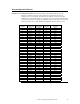


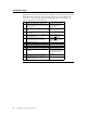

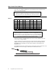


Table Of Contents
- 1 Overview
- 2 Introduction to RAID
- 3 RAID Levels
- 4 Features
- 5 Configuring MegaRAID Express 500
- 6 Hardware Installation
- Checklist
- Installation Steps
- Summary
- 7 Cluster Installation and Configuration
- Software Requirements
- Hardware Requirements
- Installation and Configuration
- Driver Installation Instructions under Microsoft Windows 2000 Advanced Server
- Network Requirements
- Shared Disk Requirements
- Cluster Installation
- Installing the Windows 2000 Operating System
- Setting Up Networks
- Configuring the Cluster Node Network Adapter
- Configuring the Public Network Adapter
- Verifying Connectivity and Name Resolution
- Verifying Domain Membership
- Setting Up a Cluster User Account
- Setting Up Shared Disks
- Configuring Shared Disks
- Assigning Drive Letters
- Verifying Disk Access and Functionality
- Cluster Service Software Installation
- Configuring Cluster Disks
- Validating the Cluster Installation
- Configuring the Second Node
- Verify Installation
- SCSI Drive Installations
- Configuring the SCSI Devices
- Terminating the Shared SCSI Bus
- 8 Troubleshooting
- A SCSI Cables and Connectors
- B Audible Warnings
- C Cluster Configuration with a Crossover Cable
- Glossary
- Index
MegaRAID Express 500 Hardware Guide
54
Step 5 Set Jumpers,
Continued
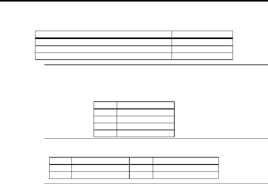
J1 Termination Enable
J1 is a three-pin header that specifies hardware or software control of SCSI
termination.
Type of SCSI Termination J10 Setting
Software control of SCSI termination via drive detection. Short Pins 1-2
Permanently disable all onboard SCSI termination. Short Pins 2-3
Permanently enable all onboard SCSI termination. OPEN
J9 I2C Interface Connector
J9 is a four-pin header that allows the i960JX core processor to serve as a
master and slave device that resided on the I2C bus when used with the I2C Bus Interface
Unit. Attach a four-wire cable from J9 to the I2C Bus Interface Unit.
Pin Description
1SDA
2GND
3SCL
4VCC
J5 Serial Port
J5 is a 3-pin berg that attaches to a serial cable. The pinout is:
Pin Signal Description Pin Signal Description
1 RXD 2 TXD
3GND
Cont’d