Lucas Control Systems Deeco Systems EM-C061 14" Flat Panel Display Embedded Computer Module USER MANUAL Manual P/N: 15062 Manual Revision: 1.
How to contact Deeco Systems for sales or technical support: Lucas Control Systems, Deeco Systems 31047 Genstar Road Hayward, California USA 94544-7831 Phone: 1-800-376-1154 or 510-471-4700 FAX: 510-489-3500 General E-mail: sales@deeco.com Internet: http://www.deeco.com Technical Support E-mail: LDTECHSUPPORT@COMPUSERVE.
Warning!! Grounding circuit continuity is vital for safe operation of the machine. Never operate the machine with the grounding conductor disconnected. See installation instructions before connecting to the supply. The computer system contains voltages capable of producing a dangerous electrical shock. Only properly trained and authorized personnel should access the computer. CAUTION: DISCONNECT POWER BEFORE SERVICING.
Table of Contents 1.0 OVERVIEW............................................................................................................................. 1 1.1 PRODUCT SUMMARY............................................................................................................ 1 1.2 INDUSTRIAL COMPUTERS ................................................................................................... 2 1.3 SINGLE BOARD COMPUTER .......................................................................
8.4 SINGLE BOARD COMPUTER................................................................................................ 27 9.0 COMPONENT TEST PROCEDURE.................................................................................... 29 9.1 POWER SUPPLY..................................................................................................................... 29 10.0 COMPONENT INSTALLATION AND REMOVAL.......................................................... 33 10.1 TOUCH CONTROLLER BOARD .....
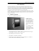
EM-C061 Computer User Manual 1.0 Overview Lucas Control Systems, Deeco™ Systems offers a complete line of rugged computers, VGA monitors, and terminals. These products are available in sealed standalone enclosures, with panel mount brackets, and as embedded modules. All Deeco Systems products are available with touch systems for a complete user interface. Deeco Systems has manufactured quality flat panel display based products for harsh and industrial applications for more than a decade.
EM-C061 Computer User Manual 1.2 INDUSTRIAL COMPUTERS Deeco computers are designed for industrial conditions and exposure to harsh environments including extended high and low temperatures, high and low humidity, and severe shock and vibration. The optional sealed front bezel meets NEMA 4/12 (IP65) requirements. Deeco computers are available with Deeco’s Power Assist factory automation software, which speeds implementation of the EM-C061 in industrial control applications.
EM-C061 Computer User Manual 1.4 ORDERING INFORMATION Base System Configuration Select a Computer and Chip Set *a ❏ ❏ ❏ ❏ 123 120 121 122 Full Size ISA/PCI SBC, 100 MHz Pentium Full Size ISA/PCI SBC, 133 MHz Pentium Full Size ISA/PCI SBC, 166 MHz Pentium Full Size ISA/PCI SBC, 200 MHz Pentium Select Memory 72-Pin EDO SIMM ❏ ❏ ❏ ❏ 211 212 213 214 8MB SIMM 16MB SIMM 32MB SIMM 64MB SIMM Select a Display ❏ 3261 XGA (1024 x 768) up to 4K colors, 13.
EM-C061 Computer User Manual Floppy Drive ❏ 600 Mounted Floppy Drive (Rear Access) PC/104 Semiconductor Disks ❏ 1010 ❏ 1011 2MB on PC/104 Card 8MB on PC/104 Card Ethernet LAN Communications *e ❏ 904 10BASE-T (T-pair) / 10BASE-2 Software - Operating Systems ❏ ❏ ❏ ❏ 800 803 811 812 Microsoft Windows 3.1 DOS Microsoft Windows 95 Microsoft Windows NT for Workstations Software - Touch Drivers ❏ 816 DOS/Microsoft Windows 3.
EM-C061 Computer User Manual 1.5 SPECIFICATIONS CPU Pentium processor up to 200 MHz L2 Cache 512K pipeline burst mode Displays 13.8" XGA (1024 x 768), AM Color TFT LCD Video Controller Chips and Technology 65XXX Memory Includes two to four 72-pin SIMM sockets supporting up to 128 MB DRAM Connectors Serial Parallel Network (optional) Keyboard Weight 26 lbs (11.82 kg) Dimensions (1502) Standard With Optional Front Panel 11.5" H x 14.4" W x 4.0" * D (292 mm x 366 mm x 102 mm) 12.3" H x 15.
EM-C061 Computer User Manual 1.6 DISPLAY The display is color active matrix LCD incorporating amorphous silicon TFT. Graphics and texts can be displayed on the 1024 x 768 color panel. The TFT panel used is a low-reflection and highercolor saturation type. AMTFT technology is rapidly changing. The EM-C061 uses the latest technology in flat panel displays.
EM-C061 Computer User Manual 2.0 INSTALLATION Read this section prior to installing the computer. Following these steps will ensure a successful installation of the computer system. 2.1 UNPACKING Components used in these systems are electrostatic sensitive. Observe proper electrostatic discharge (ESD) procedures when unpacking and handling the computer. The shipping configuration of the EM-C061 will vary according to the options ordered.
EM-C061 Computer User Manual 2.2 MOUNTING The EM-C061 is designed to be mounted in enclosures, rack-mounted, mounted in walls, and integrated in systems. Other arrangements can be used as long as these standard criteria are met: • When the unit is safely mounted the installation must be able to support at least five times the unit’s weight. The unit must be rigidly fastened so that when the touch screen is used the unit will not move or fall over. The weight of the unit is 26 lbs (11.82 kg).
EM-C061 Computer User Manual 2.4 POWER REQUIREMENTS The following table specifies the electrical requirements and capabilities of the power supplies available for the computer system. Power Supply Option Voltage Current Frequency Watts Option 703 20-36 VDC 6.7 - 3.7 A DC 100 W Option 704 100-240 VAC 1.25 - 2.
EM-C061 Computer User Manual Customer Supplied ±5, ±12V: Connect ±5, ±12V and Ground to the pigtail as shown: +5V Ground Ground +12V -12V -5V 10
EM-C061 Computer User Manual 3.0 Single Board Computer Operation The separate Single Board Computer (SBC) user manual contains setup, operation, and maintenance documentation for the SBC. The SBC is factory configured by Deeco Systems, and modifications are usually unnecessary.
EM-C061 Computer User Manual 4.0 Touch System Refer to the manual on the Touch Driver Diskette for information on the optional touch system. Touch drivers are pre-installed at the factory and reside on the mass storage device.
EM-C061 Computer User Manual 5.0 Input/Output Interface Ports 5.1 SERIAL COMMUNICATIONS PORT The computer includes two serial ports, configured as COM1 and COM2. Refer to the SBC manual for configuration information. The EM-C061 includes a 12" cable with two 9-pin DSUB connectors, so customers can access the two serial ports. COM2 is disconnected from the DSUB connector on the cable and used by the touch screen when the optional touch screen is ordered.
EM-C061 Computer User Manual 5.2.2 Parallel Port Connector The parallel port uses a 25-pin IDC style DSUB.
EM-C061 Computer User Manual 5.3 KEYBOARD PORT The computer supports an AT style 101 Keyboard. Keyboard Connector (Rear View) 5.4 Pin 1 2 3 4 5 Signal KeyClk KeyData NC GND VCC 3 1 5 4 2 NETWORK COMMUNICATIONS PORT Ethernet is the most widely used of all LAN protocols. Typical characteristics of the Ethernet are: Bandwidth 10 MB/Sec Protocol CSMA/CD Frame Size 1514 bytes Max. Nodes 1024 Max. Network Span 2.8 Km There are 3 basic topologies.
EM-C061 Computer User Manual 5.4.1 10 BASE-T Connector Ethernet Network Interface RJ45 Connector Pin-Out 1 2 3 4 5 6 7 Front View Pin 1 2 3 4 5 6 7 8 Signal TX+ TXRX+ NC NC RXNC NC 5.4.2 10 BASE-2 Connector The 10 BASE-2 connector is a BNC type COAX connector.
EM-C061 Computer User Manual 6.0 Data Storage 6.1 HARD DRIVES: Drive Type 1.3GB, rugged 2.5″ PIO4 (EIDE) 2.0GB, rugged 2.5″ PIO4 (EIDE) 2.11GB, 3.5″ Ultra SCSI (Requires PCI card slot) 3.26GB, 3.5″ SCSI3 (Requires PCI card slot) 340MB, rugged 2.5″ PIO4 (EIDE) The hard drive is preconfigured and preloaded with all software options at the factory. 6.2 SOLID STATE DISKS: Refer to the separate SSD documentation shipped with the 2 MB or 8 MB SSD options. 6.
EM-C061 Computer User Manual 7.0 General Maintenance The bezel and filter are made of a plastic polymer material, so strong solvents or acids should not be used for cleaning purposes. A soft, lint-free cloth, along with a non-abrasive, non-acidic cleaner can be used to clean the touch screen. Ammonia based cleaners are fine. 7.
EM-C061 Computer User Manual 8.0 Troubleshooting Lucas Deeco maintains a repair facility at the factory and at various international locations. Call Technical Support and ask for a RA (return authorization) number before shipping computers needing repairs. Use the telephone number in the front of this manual. If the computer suddenly ceases to function, disconnect the power, and re-seat all the cables on their connectors. Be careful to re-connect all the cables correctly.
EM-C061 Computer User Manual Problem: Malfunctioning Display Sub-System to Check: • Display • Single Board Computer Motherboard (Refer to the accompanying SBC manual) • Power Supply Problem: Malfunctioning Memory Systems Sub-System to Check: • Single Board Computer Motherboard (Refer to the accompanying SBC manual) • BIOS System (Refer to the accompanying SBC manual) Problem: Mouse pointer unresponsive to touch Sub-System to Check: • Mouse Drivers • Touch controller Problem: Serial, Pa
EM-C061 Computer User Manual 8.1 POWER SUPPLY • Input Power: Check to see if the input power to the power supply meets the requirement in section 2.4 of this manual. Refer to section 9.1 for power supply test procedures. If the measured input power is not within the values shown, provide an alternative source of input power to the computer that satisfies the proper input power requirements. If the measured power falls within the values shown, proceed to the next troubleshooting guideline in section 9.1.
EM-C061 Computer User Manual 8.2 TOUCH INTERFACE 3.3" (84 mm) 3.0" (76 mm) E271-2210 ELOGRAPHICS, INC. LED P4 - + 1.8" (46 mm) 2.1" (53 mm) Power 1x2 M RS-232 Serial 2x5 M P2 P3 5 L AccuTouch Y S 1x5 M X H H1 J0 •1 2 3 4 5 6 7 8 9 10 11 1 0.15" (4 mm) 0.156" (4 mm) 8.2.1 Controller Board • Input Power: Check to see if the input power to the controller board meets the specifications in the following table.
EM-C061 Computer User Manual 8.3 DISPLAY Verify that the cable is properly connected to the SBC. Replace the cable as a part of test procedure. If display still does not work contact application engineering or otherwise return the unit to the factory. 8.4 SINGLE BOARD COMPUTER Input Power: Using the multi-meter, check to see if the input power to the SBC meets the voltage. Make sure that power pins are not shorted during the measurements. Refer to the SBC manual for power connector pinout.
EM-C061 Computer User Manual 9.0 Component Test Procedure 9.1 POWER SUPPLY This section details the procedures for testing the functionality of the power supply. Warning: • The power supply produces DC voltages that can cause a severe electric shock if handled improperly. Disconnect power before opening. Input Power: Plug the computer into the desired power source. The voltage should fall within this range at the power supply input connector.
EM-C061 Computer User Manual • Output Power: Using a multi-meter set for DC voltage, measure the potential between ground and the pins in the following table. The voltage should match the values shown when the supply is loaded.
EM-C061 Computer User Manual If no output is measured, disconnect the power supply from source voltage and check the fuse on the power supply board. • Fuse: Remove the fuse from the power supply. Measure the resistance with an ohmmeter. If the fuse is open, replace the fuse on the power supply. Power Supply Order Number 703 704 Description +24 VDC 100W 100-240 VAC 100W Value of F1 A/250 VAC, Fast Blow 2A/250 VAC, Fast Blow Different suppliers may qualify as power supply vendors.
EM-C061 Computer User Manual 10.
EM-C061 Computer User Manual Right Side View (Viewed from Front) Left Side View (Viewed from Front) 34
EM-C061 Computer User Manual 10.1 TOUCH CONTROLLER BOARD 10.1.1 Removal • Place the computer face-down on a flat surface. • Remove the 5-pin touch screen flex cable from P3 on the touch controller. • Remove the serial interface cable from the P2 header on the controller board. • Remove the 2-pin power cable. • Remove the 4 Phillips mounting screws holding the controller board to the side panel on the computer chassis. • Remove the touch controller from the computer system. 10.1.
EM-C061 Computer User Manual 10.2.2 SIMMs Installation Figure A Figure B (Photo used for illustrative purposes only. Models and configurations may vary.) • Insert the SIMM at an angle as shown in Figure A. The SIMM will not physically fit in the socket unless pin 1 of the SIMM matches pin 1 of the socket. • Gently press the SIMM into the vertical position. The SIMM will snap easily into place if the connectors are at the correct depth in the socket.
EM-C061 Computer User Manual 10.3 MICROPROCESSOR REMOVAL AND INSTALLATION Chip Removal Tool Removing the microprocessor from the socket (Photo used for illustrative purposes only. Models and configurations may vary.) Refer to the accompanying SBC User Manual for microprocessor removal and installation guidelines. Make sure the jumper settings are matching the CPU speed! The heatsink is glued to certain microprocessors. Consult the factory for replacement microprocessors with similar heat sinks.
EM-C061 Computer User Manual Appendix A: Mechanical Drawings A.1 EM-C061 COMPUTER FRONT VIEW 11.5" (292 mm) 14.4" (366 mm) Note: Dimensions shown without optional front panel. with front panel are 12.3" H x 15.2" W (312 mm x 386 mm) Drawing not to scale -- Dimensions are in inches (mm).
EM-C061 Computer User Manual A.2 EM-C061 COMPUTER REAR VIEW SBC in Standard Model Card Slots (2 PCI, SBC, 2 ISA slots or 4 ISA slots) with Backplane Option 14.4" (366 mm) 11.5" (292 mm) Power Supply Touch Controller Hard Drive / Floppy Drive Drawing not to scale -- Dimensions are in inches (mm).
EM-C061 Computer User Manual A.3 EM-C061 SIDE VIEW 2 PCI Slots SBC 2 ISA Slots 11.5" (292 mm) Power Supply Hard Drive Floppy Drive 4.0" (102 mm) without backplane 6.2" (157 mm) with backplane Drawing not to scale -- Dimensions are in inches (mm).
EM-C061 Computer User Manual A.
EM-C061 Computer User Manual A.5 EM-C061 PANEL CUT-OUTS AND MOUNTING GUIDE 11.22" (284.99 mm) 1.39" (35.31 mm) 0.32" (8.13 mm) 5.29" (134.37 mm) 43 11.0" (279.40 mm) Suggested Panel Cutout for Mounting the EM-C061 Computer without the optional front panel 8.38" (H) x 11.22" (W) (212.85 mm x 284.99 mm) 8.38" (212.85 mm) 5.16" (131.06 mm) 0.09" (2.
EM-C061 Computer User Manual 14.50" (368.30 mm) 5.8" (147.32 mm) Suggested Panel Cutout for Mounting the EM-C061 Computer with the optional front panel 11.60" (H) x 14.50" (W) ( 294.64 mm x 368.30 mm) 5.8" (147.32 mm) Center Line 0.15" (3.81 mm) 2.5" (63.50 mm) 2.5" (63.50 mm) 7.25" (184.15 mm) 7.25" (184.15 mm) Center Line 44 11.60" (294.64 mm) 0.15" (3.81 mm) 0.11" (2.
EM-C061 Computer User Manual Appendix B: Product Naming Convention EM - C 0 6 1 Platform Type Processing Configuration ST Enclosed System EM Embedded Module Designator: 0 Computers Terminals Monitors 486 - Functional Type Display Size C T M 1 2 3 4 5 6 7 Computer, CPU-based Serial Terminal Monitor system 1 NA 8.4″″ 10.4″″ 11.3″″ 12.1″″ 13.8″″ 17.
EM-C061 Computer User Manual Display Nomenclature 3fds Sequential number ID Size of display (same as specified in base unit ID #) 1 2 NA 8.4” 3 4 10.4” 11.3” Format 0 = VGA 1 = SVGA 2 = XGA 3 = SXGA 640.480 800.600 1024.768 1280.1024 Examples: 3261 = 14″ (13.8″) 1024.768 XGA display 3153 = 12″ (12.1″) 800.600 SVGA display 46 5 6 12.1” 13.
EM-C061 Computer User Manual Limited Warranty Lucas Control Systems warrants this product against defects in materials and workmanship for a period of one year (12 months) from the date of original shipment from the factory with the following exceptions: • Active Matrix LCD Display. The original equipment manufacturers warranty will apply. • Electroluminescent Display. The original equipment manufacturers warranty will apply.
EM-C061 Computer User Manual LIMITATIONS OF LIABILITY THE BUYER AND LUCAS CONTROL SYSTEMS AGREE THAT THE SOLE AND EXCLUSIVE REMEDIES FOR BREACH OF ANY WARRANTY SHALL BE REPAIR OR REPLACEMENT OF DEFECTIVE PARTS ACCORDING TO THE TERMS DESCRIBED ABOVE. LUCAS CONTROL SYSTEMS SHALL NOT BE LIABLE FOR CONTINGENT OR CONSEQUENTIAL DAMAGES TO PERSONS OR PROPERTY, AND LUCAS CONTROL SYSTEMS’ SOLE LIABILITY IS AS SET FORTH ABOVE.
EM-C061 Computer User Manual Index 1 10 BASE-T Connector, 18 A Applying Power, 8 B BIOS, 23, 24 D Diagnostics, 2 DOS, 2 E Ethernet, 17 F Fuse, 31 G Green PC, 2 I Input Power, 25, 26, 27, 29 49
EM-C061 Computer User Manual L LAN, 17 LCD, 47 M Mounting, 8, 35 Mouse, 2, 17 N Novell, 2 O OS/2, 2 Output Power, 25, 30 P Parallel Port, 16 Power, 2 Power Requirements, 9 S SBC, 15 SIMM, 27, 35 Specifications, 5 T Touch, 26, 35 Troubleshooting, 23, 24, 25, 26, 27 U UNIX, 2 50
EM-C061 Computer User Manual W Windows, 2 51