DSLPipe DSU (SDSL) User’s Guide Part Number: 7820-0657-001 For software version 7.0.
Copyright© 1999 Lucent Technologies. All Rights Reserved. This material is protected by the copyright laws of the United States and other countries. It may not be reproduced, distributed, or altered in any fashion by any entity (either internal or external to Lucent Technologies), except in accordance with applicable agreements, contracts, or licensing, without the express written consent of Lucent Technologies.
Customer Service Customer Service Customer Service provides a variety of options for obtaining information about Lucent products and services, software upgrades, and technical assistance. Finding information and software on the Internet Visit the Web site at http://www.ascend.com for technical information, product information, and descriptions of available services. Visit the FTP site at ftp.ascend.com for software upgrades, release notes, and addenda to this manual.
Customer Service Priority Technical Assistance If you need to talk to an engineer right away, call (900) 555-2763 to reach the Priority Call queue. The charge of $2.95 per minute does not begin to accrue until you are connected to an engineer. Average wait times are less than three minutes. Other telephone numbers For a menu of Lucent’s services, call (800) 272-3634). Or call (510) 769-6001 for an operator.
Important safety instructions your inquiry to Lucent’s U.S. offices. Following are the ways in which you can reach Customer Service: • Email from within the U.S.—support@ascend.com • Email from Europe, the Middle East, or Asia—EMEAsupport@ascend.com • Fax—(510) 814-2312 • Customer Support BBS (by modem)—(510) 814-2302 Write to Lucent at the following address: Attn: Customer Service Lucent Technologies 1701 Harbor Bay Parkway Alameda, CA 94502-3002 Important safety instructions A.
Important safety instructions 8 The power source has to be adequately rated to assure safe operation of the equipment. The building installation and/or power source must provide overload protection. 9 Protective earth (PE) connection is essential to ensure safe operation before connecting to the power supply and telecommunication network. Do not defeat the purpose of the grounding-type plug by modifying the plug or using an adapter.
Important safety instructions 16 When installed in the final configuration, the product must comply with the applicable safety standards and regulatory requirements of the country in which it is installed. If necessary, consult with the appropriate regulatory agencies and inspection authorities to ensure compliance. 17 A rare phenomenon can create a voltage potential between the earth grounds of two or more buildings.
Important safety instructions ! ! ! Warning: The battery can explode if incorrectly replaced. Replace the battery only with the same or equivalent type recommended by the manufacturer. Dispose of used batteries according to the manufacturer’s instructions. Avertissement: Il y a danger d'explosion si la batterie n'est pas remplacée correctement. Remplacer uniquement avec une batterie du même type ou d'un type recommandé par le fabricant.
Contents Customer Service............................................................................................. iii Important safety instructions ............................................................................. v Introduction................................................................... 1-1 DSLPipe DSU features.................................................................................. 1-2 DSLPipe DSU configuration..............................................................
1 Introduction DSLPipe DSU features . . . . . . . . . . . . . . . . . . . . . . . . . . . . . . . . . . . . . . . . . 1-2 DSLPipe DSU configuration . . . . . . . . . . . . . . . . . . . . . . . . . . . . . . . . . . . . . 1-2 DSLPipe DSU architecture . . . . . . . . . . . . . . . . . . . . . . . . . . . . . . . . . . . . . . 1-3 The DSLPipe DSU (SDSL) is a modem that allows you to send data across two dissimilar devices. The unit converts data to an SDSL format and sends it to the destination device.
DSLPipe DSU features DSLPipe DSU features The DSLPipe DSU includes the following features: • High-speed SDSL transport over a single copper twisted-pair telephone line • Symmetrical multirate data transmission from 144 Kbps to 2320 Kbps • Compatible and interoperable with major COE routers • Easy-to use • Low power consumption • Easy configuration • COE or CPE configuration • Transmission distance of almost 18,000 feet at 786 Kbps (with a 24 gauge wire) DSLPipe DSU configuration You can use
DSLPipe DSU architecture Figure 1-2 illustrates how you can use a DSLPipe DSU as COE. WAN V.35 Router A DSLPipe DSU (as COE) DSLPipe DSU (as CPE) V.35 Router B Figure 1-2. Example: Using a DSLPipe DSU as COE The DSLPipe DSU in Figure 1-2 accepts HDLC data from V.35 Router A. The unit converts the data into SDSL format and sends it, via a WAN link, to another DSLPipe DSU that is configured as CPE. That unit then sends the data to V.35 Router B.
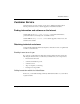
Installation 2 Checking package contents . . . . . . . . . . . . . . . . . . . . . . . . . . . . . . . . . . . . . . 2-1 Setting up the DSLPipe DSU. . . . . . . . . . . . . . . . . . . . . . . . . . . . . . . . . . . . . 2-2 Connecting the cables . . . . . . . . . . . . . . . . . . . . . . . . . . . . . . . . . . . . . . . . . . 2-4 Checking the activity of the LED lights. . . . . . . . . . . . . . . . . . . . . . . . . . . . . 2-4 The DSLPipe DSU (SDSL) modem is easy to install.
Setting up the DSLPipe DSU 1 2 3 5 4 Figure 2-1. Package contents Setting up the DSLPipe DSU Figure 2-2 shows the DSLPipe DSU’s rear panel. To set up your DSLPipe DSU, you use components located on the rear panel to set the data transmission rate, configure the unit as either CPE or COE, and connect the necessary cables Figure 2-2. DSLPipe DSU Rear Panel DC IN 2-2 RATE V.
Setting up the DSLPipe DSU Setting the data transmission rate To set the DSLPipe DSU data transmission rate, use a pen to move the DIP switches.Table 2-1 shows the DIP switch settings for each rate. Move the DIP switch down to turn the switch on. Move a switch up to turn it off. Table 2-1.
Connecting the cables Table 2-2 shows the proper setting for each configuration . Table 2-2. CPE vs. COE configuration Configuration DIP Switch 4 CPE OFF COE ON Connecting the cables To connect your DSLPipe DSU: 1 Use the V.35 to DB-25 cable to connect the V.35 device to the DSLPipe DSU. 2 Use the WAN cable to connect the DSLPipe DSU to the SDSL line. 3 Use the power supply cable to connect the DSLPipe DSU to a power source. Plugging the power supply automatically turns on the DSLPipe DSU.
Figure 2-3 shows the location of the status lights on the DSLPipe DSU front panel. Figure 2-3.
3 Viewing configuration information Items you need . . . . . . . . . . . . . . . . . . . . . . . . . . . . . . . . . . . . . . . . . . . . . . . . 3-1 Connecting serial cable and setting up communications software . . . . . . . . 3-1 Viewing configuration information . . . . . . . . . . . . . . . . . . . . . . . . . . . . . . . . 3-3 Viewing diagnostic information. . . . . . . . . . . . . . . . . . . . . . . . . . . . . . . . . . .
Connecting serial cable and setting up communications software 2 Use a communications program (such as HyperTerm, PROCOMM PLUS, Zterm, or any other program that supports VT100 terminal emulation) to open a session directly with the port to which the DSLPipe unit is connected. 3 Set your communications software to connect with the following settings: Note: If you are not already familiar with the settings listed, see the documentation for your communications software.
Viewing configuration information Press any key on the keyboard and the DSLPipe unit’s configuration menu appears: SDSL V.35 DSU Software Version 3.31 0. Show DSL Status 1. Change Configuration 2. Upgrade Operation Software 3. Upgrade SDSL Firmware 4. Debug Mode Figure 3-1. DSLPipe configuration window Note: At this time, you cannot change DSLPipe configuration, upgrade the DSLPipe software, or upgrade the DSLPipe firmware using the on-board software.
Viewing configuration information Table 3-1. Fields in the DSLPipe status window (Continued) Fields Description V35 Indicates OFF_line or ON_line Data Bit Polarity Indicates Norm (Normal) or Rev (Reverse). The default is Rev.This means that the transmitter inverts the data polarity before sending data. Sign/Magn Bit Seq Indicates Norm (Normal) or Rev (Reverse). The default is Rev. This means that the magnitude bit is followed by the sign bit. Noise Margin Shows the noise margin value (in dB).
Viewing diagnostic information Table 3-1. Fields in the DSLPipe status window (Continued) Fields Description V.35 ch Tx CRC Shows either Enable or Disable. The default is Enable. This means that the CRC is appended to the end of the frame when data is sent over the V.35 line. V.35 ch RxC Polarity Indicates Norm (Normal) or Rev (Reverse). The default is Norm.This means that data will be sampled at the rising edge of the clock. V.35 ch TxC Polarity Indicates Norm (Normal) or Rev (Reverse).
Viewing diagnostic information Table 3-2. Fields in the HDLC Registers list Fields Description HDMARXCNTA HDMARXCNTB HINTENA HINTENB HSTATA HSTATB These fields are not currently supported. HCON0A HCON0B HCON1A HCON1B SDSL_RX PACKETS Shows the number of packets received by the SDSL line. V35_RX PACKETS Shows the number of packets received by the V.35 line. V35_RX_ERROR_COUNT Shows the number of errors received by the V.35 receiver.
Viewing diagnostic information Table 3-2. Fields in the HDLC Registers list (Continued) Fields Description DMA_TXB_STATUS Shows Working if the V.35 line is working. Otherwise, shows Non-Working.
Hardware Specifications A Table A-1 lists the DSLPipe DSU specifications. Table A-1. DSLPipe DSU specifications Physical connectors RJ-11 for SDSL WAN DB-25 to V.35 connector Transmission rate 144 Kbps - 2320 Kbps DSL line code 2B1Q Line impedance 135 ohms Dimensions 220mm x 169mm x 40mm Weight Approximately 2 lbs (0.
Warranties and FCC Regulations B Product warranty . . . . . . . . . . . . . . . . . . . . . . . . . . . . . . . . . . . . . . . . . . . . . . B-1 FCC Part 15 Notice . . . . . . . . . . . . . . . . . . . . . . . . . . . . . . . . . . . . . . . . . . . . B-2 IC CS-03 Notice . . . . . . . . . . . . . . . . . . . . . . . . . . . . . . . . . . . . . . . . . . . . . . B-3 Product warranty 1 Lucent Technologies warrants that the DSLPipe V.
Warranties and FCC Regulations FCC Part 15 Notice RELATIONS. THIS WARRANTY IS IN LIEU OF ALL OTHER WARRANTIES. Warranty repair 1 During the first three (3) months of ownership, Lucent Technologies will repair or replace a defective product covered under warranty within twenty-four (24) hours of receipt of the product.
Warranties and FCC Regulations IC CS-03 Notice cause harmful interference. But if it does, the user will be required to correct the interference at his or her own expense. The authority to operate this equipment is conditioned by the requirement that no modifications will be made to the equipment unless the changes or modifications are expressly approved by Lucent Technologies. IC CS-03 Notice The Industry Canada label identifies certified equipment.