CellPipe™ 20 Series User’s Guide Part Number: 7820-0766-004 November, 2001
Copyright © 2001 Lucent Technologies Inc. All rights reserved. This material is protected by the copyright laws of the United States and other countries. It may not be reproduced, distributed, or altered in any fashion by any entity (either internal or external to Lucent Technologies), except in accordance with applicable agreements, contracts, or licensing, without the express written consent of Lucent Technologies. For permission to reproduce or distribute, please email your request to techcomm@lucent.
Customer Service Customer Service Product and service information, and software upgrades, are available 24 hours a day. Technical assistance options accommodate varying levels of urgency. Finding information and software To obtain software upgrades, release notes, and addenda for these products, log in to Lucent OnLine Customer Support at http://www.lucent.com/support. Lucent OnLine Customer Support also provides technical information, product information, and descriptions of available services.
Customer Service Obtaining assistance through email or the Internet If your services agreement allows, you can communicate directly with a technical engineer through Email Technical Support or a Live Chat. Select one of these sites when you log in to http://www.lucent.com/support. Calling the technical assistance center (TAC) If you cannot find an answer through the tools and information of Lucent OnLine Customer Support or if you have a very urgent need, contact TAC.
Contents Customer Service ..................................................................................................... iii Introduction .......................................................................... 1-1 About this guide .................................................................................................... What is the CellPipe 20 Series Product Family? ................................................... Lucent TURN-UP .......................................................
Contents Configuring a 20 Series CellPipe ...................................... 4-1 Auto-provisioning .................................................................................................. 4-1 Configuring WAN interface .................................................................................. 4-2 SDSL commands and configurations ............................................................. 4-2 ADSL commands and configurations ............................................................
Introduction 1 About this guide . . . . . . . . . . . . . . . . . . . . . . . . . . . . . . . . . . . . . . . . . . . . . . . . . . 1-1 What is the CellPipe 20 Series Product Family? . . . . . . . . . . . . . . . . . . . . . . . . . 1-2 Lucent TURN-UP. . . . . . . . . . . . . . . . . . . . . . . . . . . . . . . . . . . . . . . . . . . . . . . . . 1-3 CellPipe 20 Series management . . . . . . . . . . . . . . . . . . . . . . . . . . . . . . . . . . . . . .
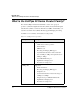
Introduction What is the CellPipe 20 Series Product Family? What is the CellPipe 20 Series Product Family? The current CellPipe 20 Series Product Family consists of two groups of products—symmetrical digital subscriber line (SDSL) and asymmetrical digital subscriber line (ADSL)—for Point-to-Point Protocol (PPP) or Frame Relay over asynchronous transfer mode (ATM). All units support IP bridging and routing. See Table 1-1 for a summary of the features for each product. Table 1-1.
Introduction Lucent TURN-UP Lucent TURN-UP The CellPipe 20 Series Product Family supports the Lucent TURN-UP™ automated CPE provisioning system. TURN-Up is enabled when a user powers up his unit and allows service providers to quickly and efficiently distribute and provision CPE gear without the use of truck-rolls. Furthermore, TURN-UP stores configuration information on a central server, making configuration management efficient and easy.
2 Setup Verifying package contents. . . . . . . . . . . . . . . . . . . . . . . . . . . . . . . . . . . . . . . . . . 2-1 Items you need for installation . . . . . . . . . . . . . . . . . . . . . . . . . . . . . . . . . . . . . . . 2-2 Connecting CellPipe 20 Series products . . . . . . . . . . . . . . . . . . . . . . . . . . . . . . . 2-2 Checking status lights. . . . . . . . . . . . . . . . . . . . . . . . . . . . . . . . . . . . . . . . . . . . . . 2-4 Console setup . . . . . . . . . . . . . . . . . . .
Setup Items you need for installation • Power supply • Warranty card Note: All CellPipe units are shipped with a power supply. However, European users need to purchase an additional wall-outlet cable because of regional variations in wall outlets. Please check with your sales representative for the item specific to your unit. Figure 2-1. Power supplies U.S.
Setup Connecting CellPipe 20 Series products Figure 2-2. CellPipe 20 Series rear panels CellPipe 20A-GX CellPipe 20S To connect up the CellPipe 20 Series units, proceed as follows: 1 2 LAN connections: • On the CellPipe 20A-GX, use the provided Ethernet cable (yellow) to connect the ETHERNET port to the NIC on a computer or to an appropriate networking component.
Setup Checking status lights Checking status lights Observe the activity pattern of the lights at the front of the CellPipe units to verify that they are connected properly. Figure 2-3. Status lights When all the cables are connected, verify that: • The pwr light comes on initially and remains on. If not on, make sure the power supply is properly connected. • The act light blinks during any LAN traffic. Otherwise it remains off. • The lnk light is on if there is an Ethernet connection established.
Setup Console setup Set your communications software to connect with the following settings: • Connection—Specify a direct connection from the unit to the computer. • Serial port—Specify the serial port on the computer the software is to use. • Terminal type—Specify VT100. • Duplex—Specify Full. This is the default for most communications software. • Bits per second—Specify 9600. • Data bits—Specify 8. • Parity—Specify None. • Stop bits—Specify 1. • Flow control—Specify None.
Command-Line Interface 3 Syntax of command-line interface . . . . . . . . . . . . . . . . . . . . . . . . . . . . . . . . . . . . 3-1 Using the commands . . . . . . . . . . . . . . . . . . . . . . . . . . . . . . . . . . . . . . . . . . . . . . 3-2 Bridging commands . . . . . . . . . . . . . . . . . . . . . . . . . . . . . . . . . . . . . . . . . . . . . . . 3-3 Routing commands. . . . . . . . . . . . . . . . . . . . . . . . . . . . . . . . . . . . . . . . . . . . . . . .
Command-Line Interface Using the commands Using the commands The CLI of the CellPipe 20 Series consists of two hierarchical levels. Some of the second-level commands display values or status of the selected commands from the main level. Note: Access to the CLI is possible without a password. When user enables a password, the unit will time-out after 10 minutes if there is no activity on the unit. Re-entering password is necessary to resume activity.
Command-Line Interface Bridging commands Returning to the main menu To return to the main commands, enter the home command: >lan> home Displaying second-level commands To select a second-level command, enter the command at the > prompt: >adsl> show Saving configurations To save a value or configuration, enter the save command and type y: >> save Are you sure that you want to save the new changes?(y/n)y Note: All settings have to be saved to take effect.
Command-Line Interface Bridging commands save show ver - save and restart modem - display configuration of PVC and Ethernet - display software version Note: *The WAN interface displayed in the menu is dependent on the interface supported by your unit. This generic form of presentation has been arrived at to eliminate the need of representing every interface. Table 3-1 lists the main menu commands and their corresponding second-level menus.
Command-Line Interface Bridging commands Table 3-1.
Command-Line Interface Routing commands Table 3-1.
Command-Line Interface Routing commands The following main menu commands are displayed for routing mode: xdsl* default dnsrelay ipoa lan list manage mode pat ping pppoa quick r1483 restart rtable save show ver - entry to xdsl menu set all configuration to factory setting entry to DNS Relay menu entry to IPoA menu entry to Ethernet list status for enabled PVC entry to management menu exit this menu and change modem mode entry to PAT menu ping IP for testing purpose entry to PPPoA menu quick setup entry to
Command-Line Interface Routing commands Table 3-2.
Command-Line Interface Routing commands Table 3-2.
Configuring a 20 Series CellPipe 4 Auto-provisioning. . . . . . . . . . . . . . . . . . . . . . . . . . . . . . . . . . . . . . . . . . . . . . . . . 4-1 Configuring WAN interface . . . . . . . . . . . . . . . . . . . . . . . . . . . . . . . . . . . . . . . . . 4-2 Configuring LAN interface . . . . . . . . . . . . . . . . . . . . . . . . . . . . . . . . . . . . . . . . . 4-7 Configuring the manage command . . . . . . . . . . . . . . . . . . . . . . . . . . . . . . . . . . .
Configuring a 20 Series CellPipe Configuring WAN interface When you power up the unit, it is set to default (factory settings) and the console will display the following message: Starting to download from remote server... This means TURN-UP is enabled and is downloading the latest configuration information. To disable the feature, interrupt the download and manually configure the system. To re-enable the feature, you need to select the default command and reinstall the factory default configuration.
Configuring a 20 Series CellPipe Configuring WAN interface Select the cell command to enable or disable the idle-cell header. >sdsl> cell Select the dbit command to configure the sdsl data bit. >sdsl> dbit Select the default command to set the SDSL configuration back to factory setting. >sdsl> default Set SDSL configuration back to factory setting Select the enable command to activate the last updated SDSL parameters.
Configuring a 20 Series CellPipe Configuring WAN interface >sdsl> smbit Select the status command to display the configuration and status of the current SDSL setting. For example: >sdsl> status >version : Ver 2.31 Date 19/Feb/2001 terminal - cpe auto - enable rate - 2320 maxrate - 2320 smbit - reverse dbit - normal scramble - enabled cell - disabled Status : Bitpump F/W Version : 5.
Configuring a 20 Series CellPipe Configuring WAN interface coding - <0>|<1>|<2>|<3>|<4>|<5>|<6>| dB - coding gain counts - display ADSL counters default - reset to default ADSL setting ec_fdm - | - set EC or FDM mode rx_bin - show - display ADSL parameter configuration startup - restart ADSL line status - display ADSL line status stnl - ||| trellis - | - Trellis encoding tx_pwr - <0> ..
Configuring a 20 Series CellPipe Configuring WAN interface Select the rx_bin command to limit the bin number used for special configurations in the receive signal. Values for bin numbers are between 1 to 255. >adsl> rx_bin - Select the show command to display the ADSL parameter configuration.
Configuring a 20 Series CellPipe Configuring LAN interface AS0_Dn_Latency_Actual LS0_Up_Bytes_Actual LS0_Up_Latency_Actual Fast_R_Up_Actual Interleave_S_Up_Actual Interleave_D_Up_Actual Interleave_R_Up_Actual Fast_R_Dn_Actual Interleave_S_Dn_Actual Interleave_D_Dn_Actual Interleave_R_Dn_Actual 0 0 0 0 0 0 0 0 0 Select the stnl command to configure the local ADSL coding type. >adsl> stnl - ||
Configuring a 20 Series CellPipe Configuring LAN interface fullduplex setip show - fullduplex | - setup the IP address, and subnet mask for Ethernet connection - show LAN configuration Select the fullduplex command to enable or disable fullduplex. >lan> fullduplex | Select the setip command to set up the IP address and subnet mask for the LAN link. For example: >lan> setip 192.168.2.32 Set a new IP address = 192.168.2.32 and Subnet mask is default = 255.255.255.
Configuring a 20 Series CellPipe Configuring the manage command Select the dhcpserver command to configure the range of IP addresses that are associated with the subnet mask used for the DHCP server. >lan> dhcpserver [ ] [] - dhcpserver dns [] Select the setdhcp command to set the DHCP mode of the unit.
Configuring a 20 Series CellPipe Configuring the quick command >>mode Please select bridge or router:(b/r,r) Configuring the quick command The quick command allows you to easily configure your LAN connections in either the bridging or routing mode. The quick command in bridging mode The quick command in bridging mode allows you to easily configure eight PVCs. For example: >> quick 1 PVC existed, 7 PVCs available.
Configuring a 20 Series CellPipe Configuring the r1483 command >>quick R1483(r)/ IPoA(i)/ PPPoA(p): ipoa 0 PVC existed, 8 PVCs available. Ethernet IP (149.198.65.46) : Subnet mask (255.255.255.0) : VPI(0-1023): 5 VCI(1-65535): 33 WAN IP : 148.198.6.46 Gateway : 148.198.6.90 >>quick R1483(r)/ IPoA(i)/ PPPoA(p): pppoa 0 PVC existed, 1 PVC available. Ethernet IP (149.198.65.46) : Subnet mask (255.255.255.
Configuring a 20 Series CellPipe Configuring the r1483 command setspan show - | spanning tree - show RFC1483 configuration Select the delpvc command to delete one or all PVCs. >r1483> delpvc |[/] Select the pfilter command to set the packet filter type. >r1483> pfilter [/] Select the setpvc command to set the PVCs in bridging mode.
Configuring a 20 Series CellPipe Configuring the dnsrelay command Select the setwanip command to set PVC and the IP address for routing. >r1483> setwanip [/] ]> Select the show command to display the RFC1483 configuration.
Configuring a 20 Series CellPipe Configuring the pppoa command Select the setqos command to set the class for quality of service. >ipoa> setqos [/] Select the setrip command to set the PVC for RIP. >ipoa> setrip [/] <1|2|1&2|0> Select the setwanip command to set up to eight PVCs, the WAN IP addresses for each PVC, and the gateway IP address. >ipoa> setwanip [/] ]> Select the show command to display the IPoA configuration.
Configuring a 20 Series CellPipe Configuring the pat command Confirm Password again: ****** Pass has been changed Select the deluser command to delete a user of a pppoa connection. >pppoa> deluser Select the echo command to input the echo time interval and enable LCP echo cancellation. >pppoa> echo Select the setllc command to enable or disable logic link control (LLC). >pppoa> setllc nable|isable Select the setqos command to set the class for quality of service.
Configuring a 20 Series CellPipe Configuring the pat command Select the addpatin command to enable a local server’s IP address to be used as a WAN access port. >pat> addpatin / Note: Prior to setting the local server as a WAN access port, you have to enable the PAT function. See the setpat command below. Select the delpatin command to disable the local server as a WAN access port.
Upgrading System Software 5 Preparing to upgrade. . . . . . . . . . . . . . . . . . . . . . . . . . . . . . . . . . . . . . . . . . . . . . . 5-1 Obtaining software . . . . . . . . . . . . . . . . . . . . . . . . . . . . . . . . . . . . . . . . . . . . . . . . 5-1 Upgrading software . . . . . . . . . . . . . . . . . . . . . . . . . . . . . . . . . . . . . . . . . . . . . . .
Upgrading System Software Upgrading software Upgrading software Follow the procedure below to upgrade software: 1 Extract the loads from eSight to your computer. 2 Establish an Ethernet connection between the unit and your computer. 3 Set up IP addresses on the unit and your computer such that you can successfully ping the unit. 4 Under the DOS prompt on your computer, enter the path to the directory containing the extracted loads and a file named xupgrade.bat.
Warranties and FCC Regulations Product warranty . . . . . . . . . . . . . . . . . . . . . . . . . . . . . . . . . . . . . . . . . . . . . A-1 FCC Part 15 Notice . . . . . . . . . . . . . . . . . . . . . . . . . . . . . . . . . . . . . . . . . . . A-2 IC CS-03 Notice . . . . . . . . . . . . . . . . . . . . . . . . . . . . . . . . . . . . . . . . . . . . . .
Warranties and FCC Regulations FCC Part 15 Notice BUSINESS RELATIONS. THIS WARRANTY IS IN LIEU OF ALL OTHER WARRANTIES. Warranty repair 1 During the first three (3) months of ownership, Lucent Technologies will repair or replace a defective product covered under warranty within twenty-four (24) hours of receipt of the product.
Warranties and FCC Regulations IC CS-03 Notice interference. But if it does, the user will be required to correct the interference at his or her own expense. The authority to operate this equipment is conditioned by the requirement that no modifications will be made to the equipment unless the changes or modifications are expressly approved by Lucent Technologies. IC CS-03 Notice The Industry Canada label identifies certified equipment.