
IP Phone User Manual
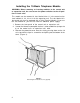
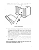


4. Align the module in the slot (Figure 3), making sure the edges of the
circuit board are in the top and bottom grooves of the slot.
Figure 3
Installing the Module (Typical)
5. Slide the module into the slot until the latch at the bottom of the module
catches at the base of the slot. With one hand, press firmly at the front
of the module while using the other hand to snap the latch into place.
NOTE: If you have any difficulties, remove the 10-Basic Telephone
Module and check the connectors at the back of the module and at
the back of the slot. Check for bent pins or other damage that prevents
the connectors from matching properly. If you find any damaged pins,
contact your equipment supplier.
6. The ten front panel jacks on the module accept 4-pair modular cords,
which are used to connect the jacks on the module with the appropriate
jacks in the jack field. Building wiring is used between the jack field
and the telephones. Refer to the Installation Guide: Models 1030 and
3070 for details.
To connect basic telephones to the module once it has been installed, refer
to the Installation Guide: Models 1030 and 3070.
3