
user manual

DEFINITY Enterprise Communications Server Release 5
Maintenance and Test for R5vs/si
555-230-123
Issue 1
April 1997
Maintenance Object Repair Procedures
Page 10-545DS1-BD (DS1 Interface Circuit Pack)
10
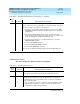
Loss of Signal Alarm Inquiry Test (#138)
This test verifies the synchronization status and continuity of the DS1 link. The
Loss of Signal alarm indicates that the DS1 Interface circuit pack is unable to
derive the synchronization clock from the DS1 facility. When the DS1 Interface
FAIL DS1 Interface circuit pack failed in the Internal Looparound Test.
1. Retry the command at 1-minute intervals a maximum of 5 times.
2. If the DS1 Interface circuit pack is TN767, enter the list measurement
ds1-log PCSS command to read the error seconds measurement.
Otherwise, skip this step.
3. Verify that both endpoints of the DS1 link are administered using the
same signaling mode, framing mode, and line coding.
4. Check the physical connectivity of DS1 Interface circuit packs and cable.
5. If all of the above are OK, replace the local DS1 Interface circuit pack and
repeat the test.
6. Contact T1 Network Service to diagnose remote DS1 endpoint.
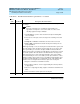
PASS All administered trunks of DS1 Interface circuit pack pass the Internal
Looparound Test. The bit pattern consistency test is executed successfully
over the path that covers a DS1 port, cable, and the external NCTE device.
0NO
BOARD
The test could not relate the internal ID to the port (no board).
This could be due to incorrect translations, no board is inserted, an incorrect
board is inserted, or an insane board is inserted.
1. Check to ensure that the board translations are correct. Use the add ds1
PCSS command to administer the DS1 interface if it is not already
administered.
2. If board was already administered correctly, check the error log to
determine if the board is hyperactive. If this is the case, the board is shut
down. Reseating the board will re-initialize the board.
3. If the board was found to be correctly inserted in step 1, issue the
busyout board command.
4. Issue the reset board command.
5. Issue the release busy board command.
6. Issue the test board long command.
This should re-establish the linkage between the internal ID and the port.
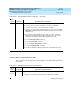
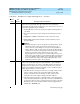
Table 10-149. TEST #135 Internal Looparound Test — Continued
Error
Code
Test
Result Description/ Recommendation
Continued on next page