
user manual

DEFINITY Enterprise Communications Server Release 5
Maintenance and Test for R5vs/si
555-230-123
Issue 1
April 1997
Maintenance Object Repair Procedures
Page 10-1001PDMODULE, TDMODULE (Data Module)
10
PDMODULE, TDMODULE (Data
Module)
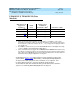
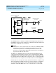
As illustrated in Figure 10-74, data modules provide an interface between the
system TN754, TN784, TN413 [G3iV2-386], or TN754 [G3iV2-386] Digital Line
circuit pack and data equipment such as terminals, host computers, and
modems. Data modules are used for both dial-up and permanent
circuit-switched data calls. DA data modules provide this interface when the
system uses a TN2136 [G3iV2-386] Digital Line circuit pack.
1. Where P is the port network number (1 for PPN and 2 or 3 for EPN); C is the carrier
designation (for example, A, B, C, D, or E); SS is the address of the slot in the carrier where
the circuit pack is located (for example, 01, 02, ..., etc.); and pp is the 2-digit port number
(for example, 01).
2. The DTDM is considered to be part of the DIG-LINE MO. Refer to the Digital Line testing
section for DTDM or linked Data Adapter (DA) failures.
3. Some of the alarms that are logged due to PDMODULE and TDMODULE test failures may
be related to circuit pack problems reported during the Common Port Circuit Pack testing
phase. Refer to the XXX-BD (Common Port Circuit Pack) Maintenance documentation for
information about testing the Digital Line circuit packs.
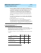
MO Name As It
Appears in
Alarm Log
Alarm
Level
Initial System
Technician
Command to Run
1
Full Name of MO
PDMODULE
2,3
MINOR test port PCSSpp l Processor Data Module
PDMODULE WARNING test port PCSSpp sh Processor Data Module
TDMODULE
2,3
MINOR test port PCSSpp l Trunk Data Module
TDMODULE WARNING test port PCSSpp sh Trunk Data Module