
User's Manual


DEFINITY Enterprise Communications Server Release 8.2
Upgrades and Additions for R8r
555-233-115
Issue 1
April 2000
Adding or Removing Cabinet Hardware
6-115Add a Switch Node Carrier (High or Critical Reliability)
6
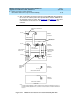
Figure 6-40. Locations of Top and Bottom Ground Straps on Standard and
Enhanced Carriers
8. If a switch node carrier is being installed in the “D” position of the PPN,
install the TDM/LAN cable (between the “E” and “D” carriers) to the
pin-field block marked “TDM/LAN” on the right side of both carriers. See
Figure 6-41
and
Table 6-10
.
Figure Notes
1. Standard AC-powered Carrier
2. Enhanced Carrier (in R8r PPNs using
either AC power [U.S.] or Global
power)
3. Top Ground Straps
4. Bottom Ground Straps
P1 P1
1 2
lcdfgrn2 KLC 022100
G
9
G
9
G
1
0
0
0
0
1
T
D
M
/
L
A
N
ICCA
ICCB
0
2
03
04
G
1
G
2
7
8
1
0
1
1
1
3
2
4
5
6
3
4
3
4