
User's Manual


DEFINITY Enterprise Communications Server Release 8.2
Upgrades and Additions for R8r
555-233-115
Issue 1
April 2000
Adding or Removing Cabinet Hardware
6-119Add a Switch Node Carrier (High or Critical Reliability)
6
Interconnect Port Networks
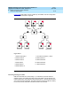
1. Behind the PPN cabinet (See Figure 6-37):
a. Connect the metallic intracarrier cable between slots 1E01 and
1E02.
b. Connect the metallic intracarrier cable between slots 1D01 and
1D02.
2. Behind switch node carrier E of PPN cabinet 1 (See Figure 6-37
):
a. For each EPN, install one 9823-type lightwave transceiver on the
following order of slots: 1E20, 1E03, 1E19, 1E04, 1E18, 1E05, and
so forth.
b. Connect 1 end of each fiber optic cable to each lightwave
transceiver, just installed.
c. Carefully attach the fiber optic cables (with cable ties) to the wall of
the cable tray at the built-in cable-tie positions.
3. Behind control carrier A of each EPN cabinet:
a. Install a lightwave transceiver on slot A01.
b. Connect the other end of the fiber optic cable to the lightwave
transceiver, just installed.
c. Carefully attach the fiber optic cable (with cable ties) to the wall of
the cable tray at the built-in cable-tie positions.
d. Coil up the surplus length of fiber optic cable, and carefully attach
the coil to the wall of the cable tray.
4. Behind switch node carrier D of PPN cabinet 1 (See Figure 6-37
):
a. For each EPN, install a lightwave transceiver on the following order
of slots: 1E20, 1E03, 1E19, 1E04, 1E18, 1E05, and so forth.
b. Connect 1 end of each fiber optic cable to each lightwave
transceiver, just installed.
c. Carefully attach the fiber optic cables (with cable ties) to the wall of
the cable tray at the built-in cable-tie positions.
5. Behind port carrier B of each EPN cabinet:
a. Install a lightwave transceiver on slot B02.
b. Connect the other end of the fiber optic cable to the lightwave
transceiver, just installed.
c. Carefully attach the fiber optic cable (with cable ties) to the wall of
the cable tray at the built-in cable-tie positions.
d. Coil up the surplus length of fiber optic cable, and carefully attach
the coil to the wall of the cable tray.