DEFINITY® Enterprise Communications Server Release 8.
Copyright 2000, Lucent Technologies All Rights Reserved Printed in U.S.A. Notice Every effort was made to ensure that the information in this book was complete and accurate at the time of printing. However, information is subject to change. Your Responsibility for Your System’s Security Toll fraud is the unauthorized use of your telecommunications system by an unauthorized party, for example, persons other than your company’s employees, agents, subcontractors, or persons working on your company’s behalf.
Issue 1 April 2000 DEFINITY ECS Release 8.
Issue 1 April 2000 DEFINITY ECS Release 8.2 ATM Installation, Upgrades, and Administration 555-233-124 Contents iv 5 6 A B ■ R6.
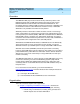
DEFINITY ECS Release 8.2 ATM Installation, Upgrades, and Administration 555-233-124 Issue 1 April 2000 About This Book v About This Book This book provides procedures for installing ATM switches and upgrading existing DEFINITY® Enterprise Communications Servers to a Release 8.2 ATM-PNC or ATM-CES. It specifically covers ■ Installing a new DEFINITY ECS that uses ATM-PNC ■ Replacing the center stage switch (CSS), the central interface between the PPN and EPNs, with ATM-PNC ■ Upgrading Release 6.
DEFINITY ECS Release 8.2 ATM Installation, Upgrades, and Administration 555-233-124 Issue 1 April 2000 About This Book Overview vi Overview The DEFINITY ATM (asynchronous transfer mode) combines portions of the DEFINITY platform with an ATM switch platform that meets specific criteria. DEFINITY ATM offers both intraswitch and interswitch ATM solutions.
DEFINITY ECS Release 8.2 ATM Installation, Upgrades, and Administration 555-233-124 Issue 1 April 2000 About This Book Organization vii — interactions among various Lucent organizations to prepare the customer site for equipment, translations, and scheduling upgrades and new installations — calculating the suitability of various Lucent ATM switches ■ Chapter 2, ‘‘Installing a DEFINITY ECS ATM-CES’’ provides a procedure for — hardware installation: ATM circuit packs and the ATM switch.
DEFINITY ECS Release 8.2 ATM Installation, Upgrades, and Administration 555-233-124 Issue 1 April 2000 About This Book Conventions Used in This Book viii Conventions Used in This Book Typographic ■ Information you type at the access terminal is shown in the following typeface: list system-parameters maintenance. ■ Variables are shown in the following typeface: number. ■ Field names and information displayed on the access terminal screen is shown in the following typeface: login.
DEFINITY ECS Release 8.2 ATM Installation, Upgrades, and Administration 555-233-124 Issue 1 April 2000 About This Book How to Comment on This Document ix Physical dimensions ■ All physical dimensions in this book are in English units (feet [ft]) followed by metric (centimeter [cm]) in parenthesis. ■ Wire gauge measurements are in AWG followed by the diameter in millimeters in parenthesis How to Comment on This Document Lucent Technologies welcomes your feedback.
DEFINITY ECS Release 8.
Issue 1 April 2000 DEFINITY ECS Release 8.2 ATM Installation, Upgrades, and Administration 555-233-124 About This Book Resources xi Where To Call for Technical Support Use the telephone numbers in Table 1 for the region in which the system is being installed. Table 1.
DEFINITY ECS Release 8.2 ATM Installation, Upgrades, and Administration 555-233-124 Issue 1 April 2000 About This Book Antistatic Protection xii Antistatic Protection ! WARNING: To minimize electrostatic discharge (ESD), always wear an authorized wrist ground strap when handling circuit packs or any components of a DEFINITY System. Connect the strap to an approved ground such as an unpainted metal surface on the DEFINITY ECS switch.
DEFINITY ECS Release 8.2 ATM Installation, Upgrades, and Administration 555-233-124 Issue 1 April 2000 About This Book Standards Compliance ■ MEGACOM® ■ SYSTIMAX® ■ TRANSTALK™ xiii The following products are trademarked by their corresponding vendor: ■ Audichron® is a registered trademark of Audichron Company ■ LINX™ is a trademark of Illinois Tool Works, Inc.
Issue 1 April 2000 DEFINITY ECS Release 8.2 ATM Installation, Upgrades, and Administration 555-233-124 About This Book LASER Product xiv ■ Australia AS3260 ■ IEC 825 ■ IEC 950 ■ UL1459 ■ UL 1950 ■ CSA C222 Number 225 ■ TS001 ■ ILMI 3.1 LASER Product The DEFINITY ECS switch may contain a Class 1 LASER device (IEC 825 1993) if single-mode fiber optic cable is connected to a remote expansion port network (EPN).
DEFINITY ECS Release 8.
DEFINITY ECS Release 8.2 ATM Installation, Upgrades, and Administration 555-233-124 Issue 1 April 2000 About This Book Federal Communications Commission Statement xvi Federal Communications Commission Statement Part 68: Statement Part 68: Answer-Supervision Signaling. Allowing this equipment to be operated in a manner that does not provide proper answer-supervision signaling is in violation of Part 68 rules.
Issue 1 April 2000 DEFINITY ECS Release 8.2 ATM Installation, Upgrades, and Administration 555-233-124 About This Book Federal Communications Commission Statement xvii Means of connection Connection of this equipment to the telephone network is shown in the following table. Manufacturer’s Port Identifier FIC Code SOC/REN/ A.S. Code Off/On Premises Station OL13C 9.0F RJ2GX, RJ21X, RJ11C DID trunk 02RV2-T 0.0B RJ2GX, RJ21X CO trunk 02GS2 0.3A RJ21X CO trunk 02LS2 3.
DEFINITY ECS Release 8.
Issue 1 April 2000 DEFINITY ECS Release 8.2 ATM Installation, Upgrades, and Administration 555-233-124 1 Preparing for Installation and Upgrades 1-1 Preparing for Installation and Upgrades 1 This chapter contains information on preparing for the installation or upgrade to Release 8 ATM Port Network Connectivity (ATM-PNC) and ATM Circuit Emulation Service (ATM-CES).
DEFINITY ECS Release 8.2 ATM Installation, Upgrades, and Administration 555-233-124 1 Preparing for Installation and Upgrades Request Address Information Issue 1 April 2000 1-2 Request Address Information The complete DEFINITY ECS translations require precutover administration, which, in turn, requires a customer address scheme, specifically the ATM addresses for theTN2305/TN2306 ATM interface circuit pack(s).
Issue 1 April 2000 DEFINITY ECS Release 8.2 ATM Installation, Upgrades, and Administration 555-233-124 1 Preparing for Installation and Upgrades Review Configuration and Equipment 1-3 Review Configuration and Equipment Figure 1-1 shows and example of the basic ATM connections for Release 8r and Release 8csi system using ATM-PNC and ATM-CES. For more detailed connection diagrams of the reliability options, refer to ‘‘DEFINITY ECS configurations’’ on page 1-6.
Issue 1 April 2000 DEFINITY ECS Release 8.2 ATM Installation, Upgrades, and Administration 555-233-124 Preparing for Installation and Upgrades Review Configuration and Equipment 1 1-4 Required Hardware Table 1-1 lists the required equipment for standard, high, critical reliability, and ATM network duplication configurations. Table 1-1.
Issue 1 April 2000 DEFINITY ECS Release 8.2 ATM Installation, Upgrades, and Administration 555-233-124 1 Preparing for Installation and Upgrades Review Configuration and Equipment 1-5 ■ RJ45-to-Bantam test cable from the 1541CC cable kit ■ System capacities Table 1-2 lists the maximum number of TN2305/TN2306 circuit packs allowed in a DEFINITY ECS. Table 1-2.
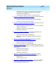
Issue 1 April 2000 DEFINITY ECS Release 8.2 ATM Installation, Upgrades, and Administration 555-233-124 1 Preparing for Installation and Upgrades Review Configuration and Equipment 1-6 DEFINITY ECS configurations Figure 1-2, Figure 1-3, and Figure 1-4 show the ATM-PNC connections for standard, high, and critical reliability, respectively. 12 11 5 5 1 9 2 10 5 7 3 8 6 10 13 5 4 cydaeps7 LJK 020100 Figure Notes 1. Public switched telephone network (PSTN) 2.
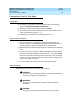
Issue 1 April 2000 DEFINITY ECS Release 8.2 ATM Installation, Upgrades, and Administration 555-233-124 1 Preparing for Installation and Upgrades Review Configuration and Equipment 1-7 11 12 5 5 1 10 8 2 5 8 3 9 7 6 8 4 5 5 cydaeph4 LJK 020100 Figure Notes 1. Public switched telephone network (PSTN) 2. Main distribution frame (MDF) or smart jack 3. Synchronization splitter 4. DS1 circuit pack (TN464F) 5. TN2305/TN2306 circuit packs 6. DEFINITY ECS access terminal 8.
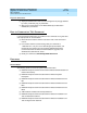
Issue 1 April 2000 DEFINITY ECS Release 8.2 ATM Installation, Upgrades, and Administration 555-233-124 1 Preparing for Installation and Upgrades Review Configuration and Equipment 1-8 13 14 5 5 12 10 5 8 8 9 7 1 6 11 8 8 2 4 5 3 5 cydaepn3 LJK 020100 Figure Notes 1. Public switched telephone network (PSTN) 2. Main distribution frame (MDF) or smart jack 8. Fiber optic cables to ATM interfaces 9. Lucent ATM switch B 3. Synchronization splitter 10. ATM switch access terminal B 4.
DEFINITY ECS Release 8.2 ATM Installation, Upgrades, and Administration 555-233-124 1 Issue 1 April 2000 Preparing for Installation and Upgrades Determine ATM Switch Suitability 1-9 Determine ATM Switch Suitability To fully support DEFINITY ATM-PNC and provide nonblocking ATM access between all port networks, ATM switches must support at least 400 point-to-multipoint switched virtual connection (SVC) roots or leaves per OC-3/STM-1 interface.
DEFINITY ECS Release 8.2 ATM Installation, Upgrades, and Administration 555-233-124 1 Preparing for Installation and Upgrades Determine ATM Switch Suitability Issue 1 April 2000 1-10 Figure 1-3 shows an example of a calculation. Table 1-3.
Issue 1 April 2000 DEFINITY ECS Release 8.2 ATM Installation, Upgrades, and Administration 555-233-124 1 Preparing for Installation and Upgrades Determine ATM Switch Suitability 1-11 UNKNOWN means that special engineering is required for this application because of the transit traffic. The special treatment is necessary because the feasibility depends on the volume of the transit traffic. Making any of the changes suggested for NO above might make it feasible regardless of the transit traffic.
Issue 1 April 2000 DEFINITY ECS Release 8.2 ATM Installation, Upgrades, and Administration 555-233-124 1 Preparing for Installation and Upgrades Determine ATM Switch Suitability Table 1-6. 1-12 Application scenarios Number of 2-party calls 2516 0 0 0 0 1258 Number of 3-party calls 0 1118 0 0 0 279 Number of 4-party calls 0 0 629 0 0 78 Number of 5-party calls 0 0 0 402 0 25 Number of 6-party calls 0 0 0 0 279 18 Table 1-7.
DEFINITY ECS Release 8.2 ATM Installation, Upgrades, and Administration 555-233-124 1 Preparing for Installation and Upgrades Determine ATM Switch Suitability Issue 1 April 2000 1-13 ATM switch is more than one. If this is the case, the calculator first attempts to determine if the application is feasible despite the transit traffic. If it is, it reports the feasibility as YES or PROBABLY. If not, it reports the feasibility as UNKNOWN, requiring special engineering.
Issue 1 April 2000 DEFINITY ECS Release 8.2 ATM Installation, Upgrades, and Administration 555-233-124 1 Preparing for Installation and Upgrades Schedule Installation or Upgrade 1-14 A limit shown as 1000000 means that this ATM switch has no independently defined limit on this resource. Table 1-8.
DEFINITY ECS Release 8.2 ATM Installation, Upgrades, and Administration 555-233-124 2 Issue 1 April 2000 Installing a DEFINITY ECS ATM-CES Equipment Installation Installing a DEFINITY ECS ATM-CES 2-1 2 This chapter describes the procedures for installing a new DEFINITY ECS Release 8 ATM-CES The procedure is simple in that you install the DEFINITY ECS then install the ATM switch and the TN2305/TN2306 interface circuit packs.
Issue 1 April 2000 DEFINITY ECS Release 8.2 ATM Installation, Upgrades, and Administration 555-233-124 Installing a DEFINITY ECS ATM-CES Equipment Installation 2 2-2 Follow the steps in Table 2-1 to ensure that ■ the applicable equipment is installed correctly. ■ the customer’s configuration is properly recorded (use worksheet in Appendix A, ‘‘Baselining the Customer’s Configuration’’). Table 2-1. General installation process √ Step 1.
Issue 1 April 2000 DEFINITY ECS Release 8.2 ATM Installation, Upgrades, and Administration 555-233-124 Installing a DEFINITY ECS ATM-CES NAA7 Board (csi/c models only) 2 2-3 Table 2-1. General installation process √ Step Action Description 7. Record configuration Record DEFINITY ECS switch-to-ATM port (port locations for each ATM circuit pack) in Table A-1 in Appendix A, ‘‘Baselining the Customer’s Configuration’’. 8.
DEFINITY ECS Release 8.
DEFINITY ECS Release 8.2 ATM Installation, Upgrades, and Administration 555-233-124 3 Issue 1 April 2000 Installing a DEFINITY ECS ATM-PNC Equipment Installation Installing a DEFINITY ECS ATM-PNC 3-1 3 This chapter describes the procedures for installing a new DEFINITY ECS Release 8 ATM system.
Issue 1 April 2000 DEFINITY ECS Release 8.2 ATM Installation, Upgrades, and Administration 555-233-124 Installing a DEFINITY ECS ATM-PNC Equipment Installation 3 3-2 Slot restrictions for an ATM interface circuit packs are similar to expansion interface circuit packs: ■ PPN: ATM interface circuit packs used for ATM-PNC must occupy the slots labeled EXPANSION INTERFACE.
Issue 1 April 2000 DEFINITY ECS Release 8.2 ATM Installation, Upgrades, and Administration 555-233-124 Installing a DEFINITY ECS ATM-PNC Synchronization Installation and Testing 3 3-3 Table 3-1. General installation process √ Step 7. 8. Action Description Connect the fiber optic cables to the ATM interface circuit packs Connect fiber optic cable to the SC connector on the faceplate of each TN2305/TN2306 circuit pack in the DEFINITY PPN and EPN.
DEFINITY ECS Release 8.2 ATM Installation, Upgrades, and Administration 555-233-124 3 Issue 1 April 2000 Installing a DEFINITY ECS ATM-PNC Synchronization Installation and Testing 3-4 Connections without synchronization splitters In some configurations the ATM switches are traced to network clocks through their SONET/SDH interfaces, not requiring any synchronization splitters. However, the ATM switch could require a single splitter if only one of the sync sources is derived from the network.
Issue 1 April 2000 DEFINITY ECS Release 8.2 ATM Installation, Upgrades, and Administration 555-233-124 3 Installing a DEFINITY ECS ATM-PNC Synchronization Installation and Testing 3-5 Installing and testing the synchronization splitter involves interrupting the DS1 signal provided by the service provider. Even though the DS1 circuit pack should be down less than 5 minutes, before removing a working T1/E1 span, contact the service provider.
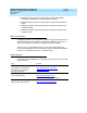
Issue 1 April 2000 DEFINITY ECS Release 8.2 ATM Installation, Upgrades, and Administration 555-233-124 Installing a DEFINITY ECS ATM-PNC Synchronization Installation and Testing 3-6 3 4 J1 2 J2 3 1 crda400a LJK 071698 Figure Notes: 1. 1. From network interface 3. Timing output port (J1) to the ATM switch1 2. Amphenol connection to DEFINITY ECS 4. Timing output port (J2) to the ATM switch1 Ports J1 and J2 provide identical DS1 timing source signals to the ATM switches.
Issue 1 April 2000 DEFINITY ECS Release 8.2 ATM Installation, Upgrades, and Administration 555-233-124 Installing a DEFINITY ECS ATM-PNC Synchronization Installation and Testing 3-7 3 2 K OR TW NE 5 nt ce Lu M AR AL s ie og ol hn c Te 1A 8 40 807 50 1 08 T M R OH 0 TE IT 10 L SP NC Y S 1 TO M AT crda401a KLC 020300 1 TO DEFINITY 3 CH IT SW 4 5 Figure Notes: 1. Amphenol connector to DEFINITY ECS 2. Network timing connection 1. 3. Timing alarm lead connection 4.
Issue 1 April 2000 DEFINITY ECS Release 8.2 ATM Installation, Upgrades, and Administration 555-233-124 Installing a DEFINITY ECS ATM-PNC Synchronization Installation and Testing 3-8 3 2 K OR TW NE M AR AL s ie og ol hn ec T nt ce Lu 5 2A 4 40 809 50 1 08 E M R OH 0 TE 12 LIT P S NC SY 1 TO M AT crda402a KLC 020300 1 TO DEFINITY 3 CH IT SW 4 5 Figure Notes: 1. Amphenol connector to DEFINITY ECS 2. Network timing connection 1. 3. Timing alarm lead connection 4.
Issue 1 April 2000 DEFINITY ECS Release 8.2 ATM Installation, Upgrades, and Administration 555-233-124 Installing a DEFINITY ECS ATM-PNC Synchronization Installation and Testing 3-9 5 4 TX K RX OR TW NE s ie og ol hn c Te nt ce Lu 3A 2 40 810 50 08 1 1 M 75 1 OH NC E SY TO M AT R TE IT L SP crda403a KLC 020300 6 TO DEFINITY 3 CH IT SW 6 3 2 Figure Notes: 1. 1. Amphenol connector to DEFINITY ECS 4. Network receive connection, BNC connector 2.
Issue 1 April 2000 DEFINITY ECS Release 8.2 ATM Installation, Upgrades, and Administration 555-233-124 Installing a DEFINITY ECS ATM-PNC Synchronization Installation and Testing 3-10 NETWORK ALARM 4 8 7 5 6 3 RX 4 3 2 1 TX 2 402A 108508094 120 OHM E1 SYNC SPLITTER 1 TO DEFINITY 3 5 TX 6 5 4 3 2 1 6 TX TO ATM SWITCH jpda40xa KLC 020300 Figure Notes: 1. Amphenol connection to DEFINITY ECS switch 2. Row of capacitors 3. Jumpers for incoming network connections 4.
Issue 1 April 2000 DEFINITY ECS Release 8.2 ATM Installation, Upgrades, and Administration 555-233-124 3 Installing a DEFINITY ECS ATM-PNC Synchronization Installation and Testing 3-11 Synchronization splitter connections The splitter connects to a timing source. Figure 3-6 shows the synchronization connections through a DSU/CSU (400A), and Figure 3-7 shows the synchronization connections through an ICSU (400A).
Issue 1 April 2000 DEFINITY ECS Release 8.2 ATM Installation, Upgrades, and Administration 555-233-124 3 Installing a DEFINITY ECS ATM-PNC Synchronization Installation and Testing 3-12 Use the information in Table 3-3 to determine the maximum cable run lengths for the configuration. 7 8 6 5 1 9 4 3 2 cydaatm1 LJK 020100 Figure Notes: 1. Public Switched Telephone Network (PSTN) 5. H600-383 quad cable from sync splitter to ATM switch A 2. Main Distribution Frame (MDF) or smart jack 6.
Issue 1 April 2000 DEFINITY ECS Release 8.2 ATM Installation, Upgrades, and Administration 555-233-124 3 Installing a DEFINITY ECS ATM-PNC Synchronization Installation and Testing 3-13 1 3 2 4 7 6 8 5 cydaatm3 KLC 020200 Figure Notes: 1. Public switched telephone network (PSTN) 5. H600-383 quad cable from sync splitter to ATM switch A 2. Main distribution frame (MDF) or smart jack 6.
Issue 1 April 2000 DEFINITY ECS Release 8.2 ATM Installation, Upgrades, and Administration 555-233-124 3 Installing a DEFINITY ECS ATM-PNC Synchronization Installation and Testing 3-14 Use the information in Table 3-3 to determine the maximum cable run lengths for the configuration. Table 3-3.
Issue 1 April 2000 DEFINITY ECS Release 8.2 ATM Installation, Upgrades, and Administration 555-233-124 3 Installing a DEFINITY ECS ATM-PNC Synchronization Installation and Testing 3-15 Table 3-4 lists the splitter model(s) applicable to specific countries. Table 3-4.
Issue 1 April 2000 DEFINITY ECS Release 8.2 ATM Installation, Upgrades, and Administration 555-233-124 3 Installing a DEFINITY ECS ATM-PNC Synchronization Installation and Testing 3-16 Table 3-4.
Issue 1 April 2000 DEFINITY ECS Release 8.2 ATM Installation, Upgrades, and Administration 555-233-124 Installing a DEFINITY ECS ATM-PNC Synchronization Installation and Testing 3 3-17 Verify the DS1 service To verify the DS1 service, use the procedure in Table 3-5. Have the ATM switch installer verify the synchronization source. Table 3-5. T1 or E1 service verification procedure √ Step Action Command Description 1. Check timing signal 2.
Issue 1 April 2000 DEFINITY ECS Release 8.2 ATM Installation, Upgrades, and Administration 555-233-124 3 Installing a DEFINITY ECS ATM-PNC Synchronization Installation and Testing Table 3-6.
Issue 1 April 2000 DEFINITY ECS Release 8.2 ATM Installation, Upgrades, and Administration 555-233-124 3 Installing a DEFINITY ECS ATM-PNC Synchronization Installation and Testing 3-19 Installing and testing the splitter The splitter must be installed and tested before the upgrade and cutover. The purpose of testing the splitter is to ■ Prove that there is enough signal level for the cable length to the ATM switch: — up to 130 ft. (39.
Issue 1 April 2000 DEFINITY ECS Release 8.2 ATM Installation, Upgrades, and Administration 555-233-124 Installing a DEFINITY ECS ATM-PNC Synchronization Installation and Testing 3 3-20 Table 3-8. Testing the splitter ports √ Step Action Command Description 1. Terminate one or more ports Plug the RJ45 (modular) end of the DS1 test cable into the jack (J1 or J2) you wish to test on the splitter. 2.
Issue 1 April 2000 DEFINITY ECS Release 8.2 ATM Installation, Upgrades, and Administration 555-233-124 Installing a DEFINITY ECS ATM-PNC Synchronization Installation and Testing 3 3-21 Connected through an ICSU. Use the procedures in Table 3-9 to install the splitter between an ICSU and a DS1 circuit pack. Table 3-9. Installing the splitter through an ICSU √ Step Action Command Description 1.
Issue 1 April 2000 DEFINITY ECS Release 8.2 ATM Installation, Upgrades, and Administration 555-233-124 Installing a DEFINITY ECS ATM-PNC Synchronization Installation and Testing 3 3-22 Table 3-9. Installing the splitter through an ICSU — Continued √ Step Action Command Description 15. Run report list measurements ds1 summary UUCSS Wait 15 minutes before entering the command. If the DS1 circuit pack is not error-free, refer to ‘‘Troubleshooting synchronization (400A only)’’ on page 6-17. 16.
Issue 1 April 2000 DEFINITY ECS Release 8.2 ATM Installation, Upgrades, and Administration 555-233-124 Installing a DEFINITY ECS ATM-PNC Synchronization Installation and Testing 3 Table 3-10. √ Step 6. 3-23 The 120A ICSU test procedure — Continued Action Reconnect the cable Command Description Connect the H600-383 cable to the smart jack or dumb block. Continued on next page 1.
Issue 1 April 2000 DEFINITY ECS Release 8.2 ATM Installation, Upgrades, and Administration 555-233-124 Installing a DEFINITY ECS ATM-PNC Synchronization Installation and Testing 3 3-24 Use the procedures in Table 3-11 to test the 120A ICSU with the 700A DS1 CPE loopback jack. Table 3-11. √ Step Testing the 120A 2 ICSU Action Command Description 1. Busyout the DS1 circuit pack busyout board UUCSS Busyout the DS1 circuit pack. 2.
Issue 1 April 2000 DEFINITY ECS Release 8.2 ATM Installation, Upgrades, and Administration 555-233-124 Installing a DEFINITY ECS ATM-PNC Synchronization Installation and Testing 3 3-25 To configure the 316X CSU to send an AIS blue alarm, use the procedures in Table 3-12. Table 3-12. √ Step Configuring the 316X CSU to send AIS blue alarm Action Description 1. Configure CSU At the 316X CSU press the double-up arrow 2. Go through the readout steps Press the button under “Cnfig.” 3.
Issue 1 April 2000 DEFINITY ECS Release 8.2 ATM Installation, Upgrades, and Administration 555-233-124 Installing a DEFINITY ECS ATM-PNC Synchronization Installation and Testing 3 3-26 To install a 400A sync splitter between a CSU or DSU/CSU and a DS1 circuit pack, follow the procedures listed in Table 3-13. Table 3-13. √ Step Splitter installation to DS1 Action Command Description 1.
Issue 1 April 2000 DEFINITY ECS Release 8.2 ATM Installation, Upgrades, and Administration 555-233-124 Installing a DEFINITY ECS ATM-PNC Synchronization Installation and Testing 3 Table 3-13. √ 3-27 Splitter installation to DS1 — Continued Step Action 11. Check for CSU alarms 12. Test the circuit pack Command Description Verify that no alarms are against the CSU (the OK, SIG, SIG LEDs are lit). test board UUCSS Verify that the DS1 circuit pack passes Tests 138 through 145.
Issue 1 April 2000 DEFINITY ECS Release 8.2 ATM Installation, Upgrades, and Administration 555-233-124 Installing a DEFINITY ECS ATM-PNC Synchronization Installation and Testing 3 Table 3-14. √ 3-28 DTE loopback testing for the 316X DSU/CSU — Continued Step 4. Action Command Continue Description Press the button under “DLB.” Test Started displays. The 316X is now in DTE loopback. 5. 6. Test the circuit pack test board UUCSS At the DEFINITY management terminal.
Issue 1 April 2000 DEFINITY ECS Release 8.2 ATM Installation, Upgrades, and Administration 555-233-124 Installing a DEFINITY ECS ATM-PNC Synchronization Installation and Testing 3 Table 3-15. √ Step 4. 3-29 RLB loopback testing for the 316X DSU/CSU — Continued Action Command Continue Description Press the button under “RLB.” Test Started displays. The 316X is now in RLB loopback. 5.
Issue 1 April 2000 DEFINITY ECS Release 8.2 ATM Installation, Upgrades, and Administration 555-233-124 Installing a DEFINITY ECS ATM-PNC Synchronization Installation and Testing 3 3-30 Installing 401A, 402A, or 403A splitters To install a 401A, 402A, or 403A sync splitter between the network and a DS1 circuit pack, follow the procedures listed in Table 3-16. Table 3-16. √ Step Splitter installation to DS1 (401A/402A/403A) Action Command Description 1.
Issue 1 April 2000 DEFINITY ECS Release 8.2 ATM Installation, Upgrades, and Administration 555-233-124 Installing a DEFINITY ECS ATM-PNC Synchronization Installation and Testing 3 Table 3-16. √ 3-31 Splitter installation to DS1 — Continued(401A/402A/403A) Step Action 11. Test the splitter Command Description Use the procedure in ‘‘Splitter port tests (401A/401A only)’’ on page 3-19. ■ Before testing the splitter, insert a modular RJ45 plug into jack J1 and jack J2 (401A/402A only).
Issue 1 April 2000 DEFINITY ECS Release 8.2 ATM Installation, Upgrades, and Administration 555-233-124 3 Installing a DEFINITY ECS ATM-PNC ATM Network Duplication 3-32 add ds1 b10 Page 1 of 2 DS1 CIRCUIT PACK Location: Bit Rate: Signaling Mode: Connect: 01B10 1.544 isdn-pri line-side Name: xxxxxxxxxxxxxxx Line Coding: b8zs Country Protocol: 1 Protocol Version: a CRC? n Interface Companding: mulaw Idle Code: 11111111 DCP/Analog Bearer Capability: 3.1kHz Slip Detection? n Screen 3-1.
DEFINITY ECS Release 8.2 ATM Installation, Upgrades, and Administration 555-233-124 3 Installing a DEFINITY ECS ATM-PNC ATM Network Duplication Issue 1 April 2000 3-33 With respect to port network connectivity, there is no difference in performance between ATM network duplication and critical reliability.
Issue 1 April 2000 DEFINITY ECS Release 8.2 ATM Installation, Upgrades, and Administration 555-233-124 3 Installing a DEFINITY ECS ATM-PNC ATM Network Duplication 3-34 8 1 6 4 2 7 9 6 3 7 5 6 7 10 cydasmpx LJK 020100 Figure Notes Figure 3-9. 1. DEFINITY ECS PPN1 6. Fiber connecting ATM switch A to EPNs 2. Fiber connecting ATM-EI A to ATM switch A 7. Fiber connecting ATM switch B to EPNs 3. Fiber connecting ATM-EI B to ATM switch B 8. DEFINITY ECS EPN1 4. Lucent ATM switch A 9.
Issue 1 April 2000 DEFINITY ECS Release 8.
Issue 1 April 2000 DEFINITY ECS Release 8.2 ATM Installation, Upgrades, and Administration 555-233-124 3 Installing a DEFINITY ECS ATM-PNC ATM Network Duplication 3-36 change system-parameters customer-options OPTIONAL FEATURES Hospitality (Basic)? Hospitality (G3V3 Enhancements)? H.323 Trunks? IP Stations? ISDN Feature Plus? ISDN-BRI Trunks? ISDN-PRI? Malicious Call Trace? Mode Code for Centralized Voice Mail? Mode Code Interface? Multifrequency Signaling? Multimedia Appl.
DEFINITY ECS Release 8.2 ATM Installation, Upgrades, and Administration 555-233-124 3 Installing a DEFINITY ECS ATM-PNC ATM Network Duplication Issue 1 April 2000 3-37 Changing circuit packs on the standby PNC To partially or completely exchange circuit packs on an ATM network duplication switch without service interruption, follow this procedure: 1. Type busyout pnc-standby and press Enter 2. Type busyout board UUCSS and press Enter 3. Replace circuit packs on the standby PNC 4.
DEFINITY ECS Release 8.
DEFINITY ECS Release 8.2 ATM Installation, Upgrades, and Administration 555-233-124 4 Upgrading to ATM-PNC Upgrade paths Upgrading to ATM-PNC Issue 1 April 2000 4-1 4 This chapter describes the procedures for upgrading a DEFINITY ECS with and without ATM-PNC to a Release 8r ATM-PNC. ATM-PNC features are only available in Release 6.3r or later systems. For information on installing a DEFINITY ECS, refer to DEFINITY Enterprise Communications Server Release 8 Upgrades and Additions for R8r.
Issue 1 April 2000 DEFINITY ECS Release 8.2 ATM Installation, Upgrades, and Administration 555-233-124 Upgrading to ATM-PNC Preparation 4 4-2 Preparation Table 4-1 lists the installation items that must be completed and the equipment or materials available before starting the upgrade procedure. We assume that in DEFINITY ECS Release 6.3r or later with ATM-PNC that the ATM switch and interface circuit packs are installed and administered. Table 4-1.
Issue 1 April 2000 DEFINITY ECS Release 8.2 ATM Installation, Upgrades, and Administration 555-233-124 4 Upgrading to ATM-PNC CSS to R8r ATM-PNC 4-3 Table 4-2.
DEFINITY ECS Release 8.2 ATM Installation, Upgrades, and Administration 555-233-124 4 Upgrading to ATM-PNC CSS to R8r ATM-PNC ■ Replace the switch node carriers in the PPNs and EPNs ■ Reterminate the TDM buses and power up the cabinets ■ Install, administer, and cable the ATM interface circuit packs Issue 1 April 2000 4-4 The following tables have the step-by-step procedures. For critical reliability and ATM network duplication, perform the steps in Table 4-3.
Load new removable media Make duplicate removable media Check health Check sync Busyout standby PNC 5. 6. 7. 8. 9. List fiber link Save translations 4. 11. Suppress alarms 3. Disable PNC duplication Log on to DEFINITY ECS 2. 10. Upgrade DEFINITY ECS to R8 Action 1. Step Determine which is the active and standby PNC (Mode field is active). Determine whether to perform a PNC interchange.
Action Busyout fiber Remove B-PNC fiber links Remove B-PNC hardware Remove circuit pack translations List cabinets Step 12. 13. 14. 15. 16. Displays numbered list of administered cabinets. Remove translations (blank out fields) for all circuit packs removed in step 13. For direct connect remove EI only. NOTE: Physically remove all EI, SNI, SNC, and DS1-CONV circuit packs (and metal cabling on back of cabinet) associated with the B-PNC fiber links just removed. Set aside reusable fiber.
Action Remove switch node administration Check status Remove PNC duplication Go to next procedure Administer B-PNC duplication Administer port connectivity for B-PNC Step 17. 18. 19. 20. 21. 22.
Action Enable PNC duplication Check administration Check health Save translations Back up disk Log off DEFINITY ECS Step 23. 24. 25. 26. 27. 28. backup disk save translation status pnc list system-link change system-parameters duplication Command Log off the DEFINITY ECS ATM Back up all changed files to the removable media. This takes about 15 minutes.
÷ Upgrade DEFINITY ECS to R8 Log on to DEFINITY switch Suppress alarms Save translations Load new removable media Make duplicate removable media Check health Check sync List fiber link Busyout fiber Remove fiber links 2. 3. 4. 5. 6. 7. 8. 9. 10. 11. Action 1.
Action Remove hardware Remove circuit pack translations List cabinets Remove switch node administration Disable sync switch Change sync source Save translations Administer ATM switch on DEFINITY Insert ATM interface circuit packs Connect fiber to ATM circuit packs Step 12. 13. 14. 15. 16. 17. 18. 19. 20. 21.
Action Administer port network connectivity Check administration Check health If critical reliability, return to previous procedure Save translations Administer synchronization source Save translations Log off DEFINITY Step 22. 23. 24. 25. 26. 27. 28. 29. Log off before powering down Save this portion of the upgrade to the fall-back removable media. Remove all DS1 timing references.
Action Power down cabinets Remove TDM busses Remove switch node carriers Reterminate TDM busses Power up Log on to DEFINITY ECS Administer replacement carriers Save translations Back up disk Log off DEFINITY ECS ATM Step 30. 31. 32. 33. 34. 35. 36. 37. 38. 39. backup disk save translation change cabinet n Command Log off the DEFINITY ECS ATM Back up all changed files to the removable media. This takes about 15 minutes.
DEFINITY ECS Release 8.2 ATM Installation, Upgrades, and Administration 555-233-124 4 Issue 1 April 2000 Upgrading to ATM-PNC R6.3r ATM-PNC to R8r ATM-PNC 4-13 R6.3r ATM-PNC to R8r ATM-PNC This section describes the procedures for upgrading a DEFINITY ECS ATM-PNC from Release 6.3r to Release 8r.
DEFINITY ECS Release 8.2 ATM Installation, Upgrades, and Administration 555-233-124 4 Upgrading to ATM-PNC R7r ATM-PNC to R8r ATM-PNC Issue 1 April 2000 4-14 R7r ATM-PNC to R8r ATM-PNC ! CAUTION: To upgrade ATM-PNC from Release 7r to Release 8r, you must have the TN2305/TN2306 circuit packs installed. Upgrading ATM-PNC from Release 7r to Release 8r does not require any additional hardware. The basic process is to upgrade the DEFINITY ECS to Release 8r first, then upgrade the ATM-PNC.
÷ Upgrade DEFINITY ECS to R7r Log on to DEFINITY switch Suppress alarms Save translations Load another tape Make duplicate removable media Check health Busyout standby PNC List all atm connections 2. 3. 4. 5. 6. 7. 8. 9. Action 1. Step Determine which is the active and standby PNC (Mode field is active). Determine whether to perform a pnc interchange.
Action Busyout connection Remove old ATM circuit packs Insert ATM circuit packs Connect fiber to B-PNC ATM circuit packs Administer ILMI/ESI information Verify circuit pack insertion Release atm connection Release the standby PNC Check link administration Step 10. 11. 12. 13. 14. 15. 16. 17. 18. Ensure that the PACLs (all PNs) and EALs (all EPNs) are up. Release the standby PNC before making any physical connections. Release all of the atm connections that were busied out in step 9.
Action Check health PNC interchange Check interchange Busyout standby PNC Repeat steps 8 through 19 Proceed to step 6 in Table 4-6. Step 19. 20. 21. 22. 23. 24. busyout pnc-standby status pnc reset pnc-interchange status pnc Command Repeat steps 8 through 19 (check health) but use a-pnc rather than b-pnc. Make the A-side the standby before removing any physical connections. Ensure that B-PNC is active and A-PNC is standby.
÷ Upgrade DEFINITY ECS to R7r Log on to DEFINITY switch Suppress alarms Save translations Load another tape Make duplicate removable media Check health List all atm connections Busyout connection 2. 3. 4. 5. 6. 7. 8. 9. Action 1. Step busyout atm pnc n (connection number) list atm pnc a-pnc status pnc save translations tape save translations tape change system-parameters maintenance Command Busyout all connections listed in step 8, beginning with A-PNC EPNs.
Action Remove old ATM circuit packs Insert ATM circuit packs Connect fiber to A-PNC ATM circuit packs Administer A-PNC ATM circuit packs Administer ILMI/ESI information Verify circuit pack insertion Release atm connection Step 10. 11. 12. 13. 14. 15. 16. release atm pnc n list configuration atm change atm pnc n (connection number) change circuit-packs n (cabinet number) Command Release all of the atm connections that were busied out in step 10.
Action Check link administration Check health Upgrade DEFINITY ECS to R8r Step 17. 18. 19.
DEFINITY ECS Release 8.
Issue 1 April 2000 DEFINITY ECS Release 8.2 ATM Installation, Upgrades, and Administration 555-233-124 4 Upgrading to ATM-PNC Screens and Tables Table 4-7. 4-22 PNC interchange A-PNC status B-PNC status Description Active Standby Go to the next step Standby Active 1. Do a PNC interchange (reset pnc-interchange) 2.
Issue 1 April 2000 DEFINITY ECS Release 8.
Issue 1 April 2000 DEFINITY ECS Release 8.2 ATM Installation, Upgrades, and Administration 555-233-124 4 Upgrading to ATM-PNC Screens and Tables 4-24 change system-parameters customer-options OPTIONAL FEATURES Hospitality (Basic)? Hospitality (G3V3 Enhancements)? H.323 Trunks? IP Stations? ISDN Feature Plus? ISDN-BRI Trunks? ISDN-PRI? Malicious Call Trace? Mode Code for Centralized Voice Mail? Mode Code Interface? Multifrequency Signaling? Multimedia Appl.
DEFINITY ECS Release 8.2 ATM Installation, Upgrades, and Administration 555-233-124 5 Issue 1 April 2000 Administering ATM-PNC and ATM-CES Accessing Switches for Administration Administering ATM-PNC and ATM-CES 5-1 5 After the hardware is upgraded to Release 8 ATM-PNC or ATM-CES, you must administer the ATM switch and and the DEFINITY ECS to complete the process.
Issue 1 April 2000 DEFINITY ECS Release 8.2 ATM Installation, Upgrades, and Administration 555-233-124 5 Administering ATM-PNC and ATM-CES Acquiring ATM Addresses 5-2 DEFINITY Network Administration (DNA) is a software-only system management tool based on client-server architecture. It gives multiple administrators the ability to administer a network of DEFINITY switches and INTUITY Voice Mail systems simultaneously from different machines.
Issue 1 April 2000 DEFINITY ECS Release 8.2 ATM Installation, Upgrades, and Administration 555-233-124 5 Administering ATM-PNC and ATM-CES Acquiring ATM Addresses 5-3 Table 5-2. ATM address formats Format Data Country Code (DCC) International Code Designator (ICD) ISDN E.
Issue 1 April 2000 DEFINITY ECS Release 8.2 ATM Installation, Upgrades, and Administration 555-233-124 5 Administering ATM-PNC and ATM-CES Administering ATM Switch 5-4 Administering ATM Switch To administer the ATM switch, refer to your switch’s quick reference guide.
Issue 1 April 2000 DEFINITY ECS Release 8.2 ATM Installation, Upgrades, and Administration 555-233-124 Administering ATM-PNC and ATM-CES Administering DEFINITY ECS 5 5-5 ATM Port Network Connectivity (ATM-PNC) Each DEFINITY port network must be translated in the PPN’s screen with the full ATM address (The ATM switch prefix, plus the port network’s ESI, plus a Selector of 0) that uniquely identifies it. Use the procedure in Table 5-4 to administer ATM-PNC: Table 5-4. ATM-PNC administration √ Step 1.
Issue 1 April 2000 DEFINITY ECS Release 8.2 ATM Installation, Upgrades, and Administration 555-233-124 Administering ATM-PNC and ATM-CES Administering DEFINITY ECS 5 5-6 Table 5-4. ATM-PNC administration — Continued √ Step Action 11. Set the MAC address (Steps 10-13) Command Description Set Address format to one of the following: E.164 ATM private, DCC, or ICD NOTE: If other ATM applications are installed ask the ATM system administrator to determine which address format to use.
DEFINITY ECS Release 8.2 ATM Installation, Upgrades, and Administration 555-233-124 5 Issue 1 April 2000 Administering ATM-PNC and ATM-CES Administering DEFINITY ECS 5-7 ATM Circuit Emulation Service (ATM-CES) ATM Circuit Emulation Service (ATM-CES): ■ Can be administered — as an ATM-CES direct connect — through an ATM network using PVCs Both procedures are in Table 5-8, under ‘‘ATM-CES administration procedure’’ on page 5-12.
Issue 1 April 2000 DEFINITY ECS Release 8.2 ATM Installation, Upgrades, and Administration 555-233-124 5 Administering ATM-PNC and ATM-CES Administering DEFINITY ECS Table 5-5. 5-8 ATM-CES administration rules Rule How to administer or confirm Both ends of the emulated circuit must have the same number of channels Type change signaling-group siggrpnbr and press Enter; go to screen 2 Both ends of the emulated circuit must have the same number of trunks.
Issue 1 April 2000 DEFINITY ECS Release 8.2 ATM Installation, Upgrades, and Administration 555-233-124 5 Administering ATM-PNC and ATM-CES Administering DEFINITY ECS Table 5-5. 5-9 ATM-CES administration rules — Continued Rule How to administer or confirm The D channel must be in a port between 009 and 032. Type display signaling-group siggrpnbr and press Enter; go to screen 2 to verify. The D channel is automatically populated in channel 24 (T1) or in channel 16 (E1).
Issue 1 April 2000 DEFINITY ECS Release 8.2 ATM Installation, Upgrades, and Administration 555-233-124 5 Administering ATM-PNC and ATM-CES Administering DEFINITY ECS Table 5-7.
Issue 1 April 2000 DEFINITY ECS Release 8.2 ATM Installation, Upgrades, and Administration 555-233-124 5 Administering ATM-PNC and ATM-CES Administering DEFINITY ECS 5-11 software makes the ATM board appear as if it does. This concept is depicted in Figure 3-1. Multiple TN2305/TN2306 circuit packs in a port network could connect to different ATM switches. 3 1 4 2 cydaces LJK 111199 Figure Notes 1. DEFINITY ECS PPN or EPN 2. TN2305/TN2306 circuit pack in any port 4.
Issue 1 April 2000 DEFINITY ECS Release 8.2 ATM Installation, Upgrades, and Administration 555-233-124 Administering ATM-PNC and ATM-CES Administering DEFINITY ECS 5 5-12 ATM-CES administration procedure Table 5-8 contains ATM-CES administration for ■ ATM signaling groups ■ ATM-CES direct-connect configurations (two CES circuit packs linked by fiber, with no intervening switches). Observe the note in step 16. NOTE: The screens shown are for a Release 8r platform.
Issue 1 April 2000 DEFINITY ECS Release 8.2 ATM Installation, Upgrades, and Administration 555-233-124 Administering ATM-PNC and ATM-CES Administering DEFINITY ECS 5 5-13 Table 5-8. ATM-CES administration — Continued √ Step Action Description 11. Set the synchronization Set the Synchronization Capable field to n (default). NOTE: Up to 44 boards may be designated synchronization capable on R8r and 3 boards on R8si, R8csi, R8c.
Issue 1 April 2000 DEFINITY ECS Release 8.2 ATM Installation, Upgrades, and Administration 555-233-124 Administering ATM-PNC and ATM-CES Administering DEFINITY ECS 5 5-14 Table 5-8. ATM-CES administration — Continued √ Step Action Description 17. Set VCI Set the Virtual Channel Identifier (VCI) field (32-1023). This number must be unique among signaling groups that share the same ATM circuit pack.
Issue 1 April 2000 DEFINITY ECS Release 8.2 ATM Installation, Upgrades, and Administration 555-233-124 Administering ATM-PNC and ATM-CES Administering DEFINITY ECS 5 5-15 Table 5-8. ATM-CES administration — Continued √ Step Action Description 27. Verify channel settings Go to screen 2; Screen 5-7 displays. Depending on the settings in step 18: ■ If Circuit Type field is set at T1, then channel 24 is populated. ■ If Circuit Type field is set at E1, then channel 16 is populated.
Issue 1 April 2000 DEFINITY ECS Release 8.2 ATM Installation, Upgrades, and Administration 555-233-124 Administering ATM-PNC and ATM-CES Administering DEFINITY ECS 5 5-16 Table 5-8. ATM-CES administration — Continued √ Step Action Description 30. Set final fields Set the following fields (tabbing goes horizontally): ■ Group Type: field to isdn. NOTE: A trunk group can contain either ISDN or ATM trunks, but not both. ■ The CDR Reports field defaults to y. ■ The Carrier Medium: field to ATM.
Issue 1 April 2000 DEFINITY ECS Release 8.2 ATM Installation, Upgrades, and Administration 555-233-124 5 Administering ATM-PNC and ATM-CES Administering DEFINITY ECS 5-17 ATM-CES administration screens NOTE: The screens shown in this section are as they look on a Release 8r platform through a SAT. Your interface and screen page numbers may differ. change system-parameters customer-options OPTIONAL FEATURES G3 Version: V8 Location: 1 Screen 5-1.
Issue 1 April 2000 DEFINITY ECS Release 8.2 ATM Installation, Upgrades, and Administration 555-233-124 5 Administering ATM-PNC and ATM-CES Administering DEFINITY ECS 5-18 change system-parameters customer-options OPTIONAL FEATURES Hospitality (Basic)? Hospitality (G3V3 Enhancements)? H.323 Trunks? IP Stations? ISDN Feature Plus? ISDN-BRI Trunks? ISDN-PRI? Malicious Call Trace? Mode Code for Centralized Voice Mail? Mode Code Interface? Multifrequency Signaling? Multimedia Appl.
Issue 1 April 2000 DEFINITY ECS Release 8.
Issue 1 April 2000 DEFINITY ECS Release 8.2 ATM Installation, Upgrades, and Administration 555-233-124 5 Administering ATM-PNC and ATM-CES Administering DEFINITY ECS 5-20 Table 5-9.
Issue 1 April 2000 DEFINITY ECS Release 8.
DEFINITY ECS Release 8.2 ATM Installation, Upgrades, and Administration 555-233-124 5 Issue 1 April 2000 Administering ATM-PNC and ATM-CES Administering DEFINITY ECS 5-22 Changing the port-to-channel mapping Use the following steps to change the port-to-channel mapping for emulated circuits: 1. Type busyout atm signaling-group siggrpnbr and press Enter to busyout the signaling group. 2. Type change trunk-group trkgrpnbr and press Enter. Remove any port administration on screen 6. 3.
Issue 1 April 2000 DEFINITY ECS Release 8.2 ATM Installation, Upgrades, and Administration 555-233-124 Administering ATM-PNC and ATM-CES Administering DEFINITY ECS 5 5-23 Additional DEFINITY ECS administration After administering the ATM-PNC or ATM-CES, you may need to do some further administration, specifically: ■ Locations ■ SVC cache (PNC only) ■ Gain/Loss adjustments (PNC only) Locations The DEFINITY ATM-PNC makes it easier for the DEFINITY ECS to have port networks in multiple time zones.
Issue 1 April 2000 DEFINITY ECS Release 8.2 ATM Installation, Upgrades, and Administration 555-233-124 Administering ATM-PNC and ATM-CES Administering DEFINITY ECS 5 Table 5-11. √ Step 5. 5-24 Administer location procedure — Continued Action Description Administer cabinet location Each cabinet in the switch and the port network(s) in that cabinet must be assigned a location number (default location number is 1). Change the Location field to the appropriate number and press Enter. 6.
Issue 1 April 2000 DEFINITY ECS Release 8.2 ATM Installation, Upgrades, and Administration 555-233-124 Administering ATM-PNC and ATM-CES Administering DEFINITY ECS 5 Table 5-11. √ 5-25 Administer location procedure — Continued Step Action Description 10. Administer Daylight-Savings Time rules Type change daylight-savings-rules and press Enter. The Daylight Savings Rules screen displays (Screen 5-13). Administer as many rules as necessary for all of the administered locations.
Issue 1 April 2000 DEFINITY ECS Release 8.2 ATM Installation, Upgrades, and Administration 555-233-124 5 Administering ATM-PNC and ATM-CES Administering DEFINITY ECS 5-26 change system-parameters customer-options OPTIONAL FEATURES Hospitality (Basic)? Hospitality (G3V3 Enhancements)? H.323 Trunks? IP Stations? ISDN Feature Plus? ISDN-BRI Trunks? ISDN-PRI? Malicious Call Trace? Mode Code for Centralized Voice Mail? Mode Code Interface? Multifrequency Signaling? Multimedia Appl.
Issue 1 April 2000 DEFINITY ECS Release 8.2 ATM Installation, Upgrades, and Administration 555-233-124 5 Administering ATM-PNC and ATM-CES Administering DEFINITY ECS 5-27 Field description: Location number associated with the cabinet (range is 1-44, default 1). Location ■ Field cannot be blank ■ Location is display-only if the Multiple locations field (change system-parameters customer-options) is not set to y.
Issue 1 April 2000 DEFINITY ECS Release 8.2 ATM Installation, Upgrades, and Administration 555-233-124 5 Administering ATM-PNC and ATM-CES Administering DEFINITY ECS 5-28 Name This15-character field identifies the location but may be blank for any given location (default = y). Timezone Offset This field specifies the time offset from the system standard time. Set a value in the ±, hour (0-23),and minute (0-59) areas, as these fields cannot be blank for an administered location.
Issue 1 April 2000 DEFINITY ECS Release 8.2 ATM Installation, Upgrades, and Administration 555-233-124 5 Administering ATM-PNC and ATM-CES Administering DEFINITY ECS 5-29 2 fields specifying the number of hours (0-23) and minutes (0-59) the clock is moved ahead to begin daylight savings time (and moved back to return to standard time). Increment NOTE: Some states (Arizona) or portions of states (Indiana) do not observe daylight savings time.
Issue 1 April 2000 DEFINITY ECS Release 8.2 ATM Installation, Upgrades, and Administration 555-233-124 5 Administering ATM-PNC and ATM-CES Administering DEFINITY ECS 5-30 SVC cache DEFINITY ATM software maintains a cache of inter-port-network connections (SVCs), with the preference given to those SVCs with the longest setup times. All cached interconnections are aged to ensure that a large number of them are not kept during nearly idle periods.
Issue 1 April 2000 DEFINITY ECS Release 8.2 ATM Installation, Upgrades, and Administration 555-233-124 5 Administering ATM-PNC and ATM-CES Administering DEFINITY ECS 5-31 Field description: Algorithm The name of the cache algorithm (default is lan). Possible values are none, lan, man, wan, and custom.
Issue 1 April 2000 DEFINITY ECS Release 8.2 ATM Installation, Upgrades, and Administration 555-233-124 Administering ATM-PNC and ATM-CES Administering DEFINITY ECS 5 5-32 Table 5-12. Gain/loss adjustment procedure √ Step 1. Action Description Set or verify gain/loss administration Type change system-parameters country-options and press Enter. The System Parameters Country-Options screen displays (Table 5-16). 2. Set digital loss plan Domestic: Ensure that the Digital Loss Plan field is 1.
Issue 1 April 2000 DEFINITY ECS Release 8.2 ATM Installation, Upgrades, and Administration 555-233-124 5 Administering ATM-PNC and ATM-CES Administering DEFINITY ECS 5-33 change system-parameters country-options Page 1 of 21 SYSTEM PARAMETERS COUNTRY-OPTIONS Companding Mode: Mu-Law 440Hz PBX-dial Tone? n Digital Loss Plan: 1 Analog Ringing Cadence: 1 Analog Line Transmission: 1 64/84xx Display Character Set? roman TONE DETECTOR PARAMETERS Tone Detection Mode: 6 Interdigit Pause: short Screen 5-16.
Issue 1 April 2000 DEFINITY ECS Release 8.2 ATM Installation, Upgrades, and Administration 555-233-124 Administering ATM-PNC and ATM-CES Final Checklist and Test 5 5-34 Final Checklist and Test After you complete all the administration, you might want to run through a final checklist and verify that everything is working. This section contains a final installation checklist and a procedure for testing the installation.
Issue 1 April 2000 DEFINITY ECS Release 8.2 ATM Installation, Upgrades, and Administration 555-233-124 Administering ATM-PNC and ATM-CES Final Checklist and Test 5 Table 5-13. √ 5-35 Final installation checklist — Continued Switch administration What to check How to check 2. ATM addresses are correct Query DEFINITY ECS 3. EALs are up Query DEFINITY ECS (list system link) Continued on next page Table 5-14. √ ATM-PNC installation test procedure What to check How to check 1.
Issue 1 April 2000 DEFINITY ECS Release 8.2 ATM Installation, Upgrades, and Administration 555-233-124 Administering ATM-PNC and ATM-CES Final Checklist and Test 5 Table 5-15. √ 5-36 ATM-CES installation test procedure What to check How to check How to fix 1. Check SONET/SDH layer for status and alarms. 2. Check the LEDs on the ATM circuit packs Refer to the maintenance book for descriptions of the LEDs, their flash rates, and the conditions indicated. 3.
DEFINITY ECS Release 8.2 ATM Installation, Upgrades, and Administration 555-233-124 6 Issue 1 April 2000 Troubleshooting 6-1 Troubleshooting 6 This chapter provides the following troubleshooting information: ■ Contact information—Lists Lucent service organizations and helplines for U.S. and international installations ■ Alarms and errors—Lists ATM maintenance objects and the platforms on which you can expect alarms and errors.
Issue 1 April 2000 DEFINITY ECS Release 8.2 ATM Installation, Upgrades, and Administration 555-233-124 6 Troubleshooting Contact information 6-2 Contact information Lucent service organizations Table 6-1 lists initial contact information for Lucent Technologies’ service and support. In cases where there is trouble and the customer cannot tell where it resides, call the Technical Service Organization (TSO) or Global Strategic Opportunities Division (GSOD) first. Table 6-1.
Issue 1 April 2000 DEFINITY ECS Release 8.2 ATM Installation, Upgrades, and Administration 555-233-124 6 Troubleshooting Alarms and errors 6-3 Helplines Table 6-2 lists various HelpLine organizations that handle postsale maintenance and general usage questions. Table 6-2.
Issue 1 April 2000 DEFINITY ECS Release 8.2 ATM Installation, Upgrades, and Administration 555-233-124 6 Troubleshooting Alarms and errors 6-4 Table 6-3.
Issue 1 April 2000 DEFINITY ECS Release 8.2 ATM Installation, Upgrades, and Administration 555-233-124 6 Troubleshooting Troubleshooting ATM-CES 6-5 Troubleshooting ATM-CES Table 6-4 provides a first-level method for troubleshooting an installation. Table 6-4.
DEFINITY ECS Release 8.2 ATM Installation, Upgrades, and Administration 555-233-124 6 Issue 1 April 2000 Troubleshooting Troubleshooting ATM-CES 6-6 Inspecting LEDs To get a high-level status of the system, observe the LEDs on the TN2305/TN2306 ATM interface circuit packs and the ATM switch. For information on interpreting the LEDs on the ATM switch, refer to your switch’s quick reference guide.
DEFINITY ECS Release 8.
Issue 1 April 2000 DEFINITY ECS Release 8.2 ATM Installation, Upgrades, and Administration 555-233-124 Troubleshooting Troubleshooting ATM-CES 6 6-8 Administration Is DEFINITY ECS ATM-CES administered correctly? D-channel problems. If the D-channel does not come up following CES administration, use the following steps to troubleshoot the cause. Table 6-5. Troubleshooting CES √ Step Action Description 1.
Issue 1 April 2000 DEFINITY ECS Release 8.2 ATM Installation, Upgrades, and Administration 555-233-124 Troubleshooting Troubleshooting ATM-CES 6 6-9 Table 6-5. Troubleshooting CES — Continued √ Step 7. Action Description Check D-channel administration The D-channel is administered in a port numbered 009–032 (display signaling-group siggrpnbr, screen 2). NOTE: The D-channel is automatically populated in channel 24 (T1) and channel 16 (E1) and this must match on both ends. 8.
Issue 1 April 2000 DEFINITY ECS Release 8.2 ATM Installation, Upgrades, and Administration 555-233-124 6 Troubleshooting Troubleshooting ATM-CES 6-10 — Standby in the EPN — CES in any PN 2.
Issue 1 April 2000 DEFINITY ECS Release 8.2 ATM Installation, Upgrades, and Administration 555-233-124 6 Troubleshooting Troubleshooting ATM-CES 6-11 — DEFINITY Enterprise Communications Server Release 8 Maintenance for R8si — DEFINITY Enterprise Communications Server Release 8 Maintenance for R8csi Possible causes 1. The TN2305/TN2306 circuit pack is in a slot different from the DEFINITY administration. 2. The TN2305/TN2306 was not completely inserted.
DEFINITY ECS Release 8.2 ATM Installation, Upgrades, and Administration 555-233-124 6 Issue 1 April 2000 Troubleshooting Troubleshooting ATM-CES 6-12 ■ Be aware that customers may use other ports on the ATM switch for applications unrelated to DEFINITY (LAN traffic or multimedia applications, for examples). ■ These other applications may manifest themselves in the output of the troubleshooting commands you run on the ATM switch.
DEFINITY ECS Release 8.2 ATM Installation, Upgrades, and Administration 555-233-124 6 Issue 1 April 2000 Troubleshooting Troubleshooting ATM-CES ■ 6-13 The ATM switch does not recognize that a port circuit pack is in the slot. You may need to re-administer the ATM switch port boards. Refer to your ATM switch’s quick reference guide for further information. Recommended Action. 1. Plug in, swap, repair, or replace the fiber as necessary. 2. Verify that the port circuit pack is completely inserted.
Issue 1 April 2000 DEFINITY ECS Release 8.2 ATM Installation, Upgrades, and Administration 555-233-124 6 Troubleshooting Troubleshooting ATM-CES 6-14 1. Type list sys-link and press Enter. Screen 6-2 shows the screen output.
DEFINITY ECS Release 8.2 ATM Installation, Upgrades, and Administration 555-233-124 6 Issue 1 April 2000 Troubleshooting Troubleshooting ATM-CES 6-15 — These virtual circuits may persist beyond the duration of a phone call. The DEFINITY Call Processing software saves virtual circuits for a few seconds after the end stations have hung up in case the VC can be used again for another call between the same two port networks.
DEFINITY ECS Release 8.2 ATM Installation, Upgrades, and Administration 555-233-124 6 Issue 1 April 2000 Troubleshooting Troubleshooting ATM-PNC 6-16 Swapped routes, end system identifiers, or fiber between a PPN and an EPN Symptoms ■ An incorrectly connected EPN TN2305/TN2306 circuit pack is not completely inserted. ■ Dial tone is present on end stations on the PPN and on correctly connected EPNs, but no dial tone is present on the affected EPN end stations.
Issue 1 April 2000 DEFINITY ECS Release 8.2 ATM Installation, Upgrades, and Administration 555-233-124 Troubleshooting Troubleshooting ATM-PNC 6 ■ 6-17 Troubleshooting interoperability—Provides guidelines for troubleshooting ■ Physical connections ■ Administration ■ TN2305/TN2306 circuit pack ■ ATM signaling architecture ■ Unusual ATM trouble conditions—Describes difficult-to-diagnose failure modes in the DEFINITY ECS and ATM switch combinations.
Issue 1 April 2000 DEFINITY ECS Release 8.2 ATM Installation, Upgrades, and Administration 555-233-124 Troubleshooting Troubleshooting ATM-PNC 6 6-18 Table 6-7. Troubleshooting 400A synchronization (through an ICSU) — Continued √ Step Action Description 3. Reseat circuit pack Reseat the DS1 circuit pack. 4. Retest the circuit pack Repeat the test (test board UUCSS). If Tests 138 through 145 pass, go to step 14 (release). If any test fails, go to step 5. 5.
Issue 1 April 2000 DEFINITY ECS Release 8.2 ATM Installation, Upgrades, and Administration 555-233-124 Troubleshooting Troubleshooting ATM-PNC 6 6-19 Connected through a DSU/CSU To troubleshoot synchronization problems in systems where the synchronization signal connects through a Data Service Unit (DSU) or Channel Service Unit (CSU), follow the procedures in Table 6-8. Use this table if the ■ DTE or RLB loopback tests fail ■ CSU or DSU/CSU does not return to normal service Table 6-8.
Issue 1 April 2000 DEFINITY ECS Release 8.2 ATM Installation, Upgrades, and Administration 555-233-124 Troubleshooting Troubleshooting ATM-PNC 6 6-20 Table 6-8. Troubleshooting 400A T1 synchronization (through a DSU/CSU) — Continued √ Step Action Description 15. If the 316X CSU or DSU/CSU fails the DTE or RLB loopback tests Remove the H600-307 DS1 cable from the splitter and the splitter from the DS1 circuit pack 16. Remove splitter Remove the splitter from the DS1 circuit pack 17.
Issue 1 April 2000 DEFINITY ECS Release 8.2 ATM Installation, Upgrades, and Administration 555-233-124 Troubleshooting Troubleshooting ATM-PNC 6 6-21 Troubleshooting synchronization (401A/402A/403A) To troubleshoot 401A/402A/403A synchronization problems, follow the procedures in Table 6-9. Table 6-9. Troubleshooting 401A/402A/403A synchronization √ Step Action Description 1.
Issue 1 April 2000 DEFINITY ECS Release 8.2 ATM Installation, Upgrades, and Administration 555-233-124 Troubleshooting Troubleshooting ATM-PNC 6 6-22 Table 6-9. Troubleshooting 401A/402A/403A synchronization — Continued √ Step Action Description 12. Escalate if necessary If the DS1 circuit pack tests OK, go to step 13. If step 11 still fails, escalate to Tier 3 or replace the splitter. 13. Release the circuit pack Release the DS1 circuit pack (release board UUCSS). 14.
DEFINITY ECS Release 8.
Issue 1 April 2000 DEFINITY ECS Release 8.2 ATM Installation, Upgrades, and Administration 555-233-124 6 Troubleshooting Troubleshooting ATM-PNC 6-24 list atm pnc Page 1 SPE A ATM PNC PNC Connection # A-PNC LOC 1 2 B-PNC LOC 01B02 02A01 Screen 6-3. Screen output for list atm pnc command Alternatively, type list configuration UUC and press Enter (noncontrol cabinets) to confirm the PPN and EPN circuit pack locations and correct insertion. 2. Type status pnc and press Enter.
Issue 1 April 2000 DEFINITY ECS Release 8.
Issue 1 April 2000 DEFINITY ECS Release 8.2 ATM Installation, Upgrades, and Administration 555-233-124 6 Troubleshooting Troubleshooting ATM-PNC 6-26 This display tells you the ATM addresses that have been administered for each TN2305/TN2306. Verify that each ATM address (the concatenation of the 5 displayed hexadecimal fields) is correct and match those in the ATM switch. Screen 6-7 shows the output for the display atm pnc 1 command; Screen 6-8 shows the output for the display atm pnc 2 command.
Issue 1 April 2000 DEFINITY ECS Release 8.2 ATM Installation, Upgrades, and Administration 555-233-124 6 Troubleshooting Troubleshooting ATM-PNC 6-27 display atm pnc 1 ATM PNC Connection Number: 1 A - PNC Location: 01B02 Name: Address Format: E.164 ATM Private AFI: E.164: HO-DSP: ESI: SEL: Screen 6-9.
Issue 1 April 2000 DEFINITY ECS Release 8.2 ATM Installation, Upgrades, and Administration 555-233-124 6 Troubleshooting Troubleshooting ATM-PNC 6-28 ATM signaling links Figure 6-2 shows the signaling links in an ATM-PNC configuration. EPN 1 PPN 1 2 3 2 1 EPN 2 2 4 1 5 6 7 cydarout LJK 020100 Figure Notes 1. DEFINITY ECS switch PPN/EPN 5. PNC ATM control link (PACL) 2. Telephones 6. Expansion archangel link (EAL) 3. ATM switch 7. ATM signaling 4.
DEFINITY ECS Release 8.2 ATM Installation, Upgrades, and Administration 555-233-124 6 Issue 1 April 2000 Troubleshooting Troubleshooting ATM-PNC 6-29 Signaling sequences. Use the information in Table 6-10 to help determine trouble with ATM signaling. Abbreviations used in this table correspond to those in Figure 6-2. Table 6-10. ATM signaling sequences Signaling between the PPN and the EPN Call between EPN2 and EPN 3 1.
Issue 1 April 2000 DEFINITY ECS Release 8.2 ATM Installation, Upgrades, and Administration 555-233-124 6 Troubleshooting Troubleshooting ATM-PNC 6-30 TN2305/TN2306 circuit pack Did the TN2305/TN2306 come up correctly? 1. Review the LED conditions for the TN2305/TN2306 (refer to the maintenance book for LED indications): ■ Do the TN2305/TN2306 LEDs indicate a normal operational state (any of the following): — Active in the PPN — Standby in the PPN — Archangel mode in the EPN — Standby in the EPN 2.
Issue 1 April 2000 DEFINITY ECS Release 8.2 ATM Installation, Upgrades, and Administration 555-233-124 6 Troubleshooting Troubleshooting ATM-PNC 6-31 list configuration carrier 2a SYSTEM CONFIGURATION Board Number Board Type 02A01 02A09 ATM PNC EI DS1 INTERFACE TN2305 TN767E 02A10 02A11 DIGITAL LINE ANALOG LINE TN754B TN746B 02A17 DIGITAL LINE TN754C Screen 6-12.
Issue 1 April 2000 DEFINITY ECS Release 8.2 ATM Installation, Upgrades, and Administration 555-233-124 6 Troubleshooting Troubleshooting ATM-PNC ■ 6-32 The Result field should show PASS for each test number. If any of the tests fail, refer to the ATM-EI maintenance objects in DEFINITY ECS Maintenance for R8r. Possible causes 1. The TN2305/TN2306 circuit pack is in a slot different from the DEFINITY administration. 2. The TN2305/TN2306 was not completely inserted.
DEFINITY ECS Release 8.2 ATM Installation, Upgrades, and Administration 555-233-124 6 Issue 1 April 2000 Troubleshooting Troubleshooting ATM-PNC 6-33 Physical layer Is there an optical signal between the TN2305/TN2306 and the ATM switch? 1. Identify the OC-3/STM-1 ports on the ATM switch that have DEFINITY port networks attached. ■ Be aware that customers may use other ports on the ATM switch for applications unrelated to DEFINITY (LAN traffic or multimedia applications, for examples).
DEFINITY ECS Release 8.2 ATM Installation, Upgrades, and Administration 555-233-124 6 Issue 1 April 2000 Troubleshooting Troubleshooting ATM-PNC ■ 6-34 The ATM switch does not recognize that a port circuit pack is in the slot. You may need to re-administer the ATM switch port boards. Refer to your ATM switch’s quick reference guide for further information. Recommended Action. 1. Plug in, swap, repair, or replace the fiber as necessary. 2. Verify that the port circuit pack is completely inserted.
DEFINITY ECS Release 8.2 ATM Installation, Upgrades, and Administration 555-233-124 6 Issue 1 April 2000 Troubleshooting Troubleshooting ATM-PNC 6-35 Q.93B (network) layer Are connection requests being received by ATM switch call control? NOTE: If there is no connection between the TN2305/TN2306 circuit pack and the ATM switch at the Q.93B protocol layer, then no report displays. 1. Check the port of interest.
Issue 1 April 2000 DEFINITY ECS Release 8.2 ATM Installation, Upgrades, and Administration 555-233-124 6 Troubleshooting Troubleshooting ATM-PNC 6-36 display errors Page 1 of 1 SPE A ERROR REPORT The following options control which errors will be displayed.
DEFINITY ECS Release 8.2 ATM Installation, Upgrades, and Administration 555-233-124 Issue 1 April 2000 Troubleshooting Troubleshooting ATM-PNC 6 Table 6-11. 6-37 Observed Cause Codes Cause Code Definition Observed Cause 3 No route to destination The ATM addresses administered in the ATM switch or in DEFINITY (display atm pnc) are incorrect. 31 Normal, unspecified This is a normal return.
DEFINITY ECS Release 8.2 ATM Installation, Upgrades, and Administration 555-233-124 6 Issue 1 April 2000 Troubleshooting Troubleshooting ATM-PNC 6-38 Are talk paths being established between port networks? Diagnostics.
DEFINITY ECS Release 8.2 ATM Installation, Upgrades, and Administration 555-233-124 6 Issue 1 April 2000 Troubleshooting Troubleshooting ATM-PNC 6-39 Incorrectly typed or omitted EPN route or end system identifier (ATM switch) Symptoms Talk paths are one-way, from the PPN to the EPN: you can hear tones from the PPN end station to the EPN end station but not vice versa.
DEFINITY ECS Release 8.2 ATM Installation, Upgrades, and Administration 555-233-124 6 Issue 1 April 2000 Troubleshooting Troubleshooting ATM-PNC 6-40 Swapped routes, end system identifiers, or fiber between two EPNs Symptoms ■ All TN2305/TN2306 circuit packs are completely inserted. ■ The PPN cold starts both incorrectly connected EPNs as usual.
DEFINITY ECS Release 8.2 ATM Installation, Upgrades, and Administration 555-233-124 6 Issue 1 April 2000 Troubleshooting Troubleshooting ATM-PNC 6-41 DEFINITY ECS ATM-PNC troubleshooting commands Wide-area networks (WAN), especially those constructed as an internet using public network facilities, may take inter-PN connectivity to the edge of acceptable performance. The switch may experience delays, blockages, or connection losses because of circumstances beyond the control of switch management.
DEFINITY ECS Release 8.2 ATM Installation, Upgrades, and Administration 555-233-124 6 Issue 1 April 2000 Troubleshooting Troubleshooting ATM-PNC 6-42 change atm pnc-pairs PNC MEASUREMENTS PAIRS Pair Orig Dest 1 2 3 4 5 6 7 8 9 PN 1 1 5 5 4 10 10 10 1 PN 5 8 8 7 2 11 12 1 10 Screen 6-16. PNC measurements pairs screen (change/display atm pnc-pairs) Field descriptions Pair Identifies the port network pair number (read only).
Issue 1 April 2000 DEFINITY ECS Release 8.2 ATM Installation, Upgrades, and Administration 555-233-124 6 Troubleshooting Troubleshooting ATM-PNC 6-43 If an administered pnc-pair is changed, the next time measurements are gathered, the today-peak entry for the old pnc-pair is replaced with an entry for the new pair, and all counters are set to 0. Screen 6-17 shows the output for this command.
Issue 1 April 2000 DEFINITY ECS Release 8.2 ATM Installation, Upgrades, and Administration 555-233-124 6 Troubleshooting Troubleshooting ATM-PNC 6-44 ATM-PNC configuration in which Inverse Multiplexing for ATM (IMA) is used going into and coming out of the network cloud. 1 10 3 4 5 9 7 8 7 2 3 6 cydaband LJK 020100 Figure Notes 1. DEFINITY ECS PPN 6. DEFINITY ECS access terminal 2. DEFINITY ECS Expansion Port Network (EPN) 7. IMA connection 3. OC-3/STM-1 connection 8. ATM network 4.
DEFINITY ECS Release 8.2 ATM Installation, Upgrades, and Administration 555-233-124 6 Issue 1 April 2000 Troubleshooting Troubleshooting ATM-PNC 6-45 network occurs. In such cases, SVC setups requested by DEFINITY can be denied by the ATM network and associated components, and calls are not completed. In this section, a failed SVC setup means that the ATM network has actively rejected the request. A delayed SVC setup means that the SVC setup exceeded a time threshold, specified in milliseconds (ms).
Issue 1 April 2000 DEFINITY ECS Release 8.2 ATM Installation, Upgrades, and Administration 555-233-124 6 Troubleshooting Troubleshooting ATM-PNC 6-46 SVC latency commands Two reports are available to help monitor the ATM network: 1. The ATM PNC Latency Histogram report (accessed through the list measurements atm latency-histogram command) shows: ■ Setup count ■ AddParty count ■ total ■ average latencies ■ histogram (21 different time bins ranging from 0-9 msec. to +10 sec.
DEFINITY ECS Release 8.2 ATM Installation, Upgrades, and Administration 555-233-124 6 Issue 1 April 2000 Troubleshooting Troubleshooting ATM-PNC 6-47 Field descriptions: Setup Count: The number of SVCs setup during the time period indicated. Values: 0 - 9999999 AddParty Count: The number of ADDPARTY requests processed. Values: 0 - 9999999 Total Count: The total number of SETUP and ADDPARTY requests.
Issue 1 April 2000 DEFINITY ECS Release 8.2 ATM Installation, Upgrades, and Administration 555-233-124 6 Troubleshooting Troubleshooting ATM-PNC 6-48 The command syntax allows you to list setup events for a particular connection number or for a range of connection numbers (Table 6-12). Table 6-12.
Issue 1 April 2000 DEFINITY ECS Release 8.2 ATM Installation, Upgrades, and Administration 555-233-124 Troubleshooting Troubleshooting ATM-PNC 6 6-49 Field descriptions: Switch Name: The value administered on the system-parameters features form. Date Time and date that the command was executed. Date System date when the event occurred (4-character).
Issue 1 April 2000 DEFINITY ECS Release 8.2 ATM Installation, Upgrades, and Administration 555-233-124 Troubleshooting Troubleshooting ATM-PNC 6 Table 6-13. √ 6-50 Constricted bandwidth administration procedure — Continued Step 3. Action Description Set alarm options Alarms generated due to impaired paths are reported against the ATM-NTWK maintenance object. The default alarm level is WARNING, but may be administered as either MINOR or WARNING.
Issue 1 April 2000 DEFINITY ECS Release 8.2 ATM Installation, Upgrades, and Administration 555-233-124 6 Troubleshooting Troubleshooting ATM-PNC 6-51 change system-parameters atm Page 1 ATM-RELATED SYSTEM PARAMETERS THRESHOLDS OF SETUP EVENTS TO DECLARE IMPAIRMENT Activation (%): Deactivation (%): Timeout (msec): 4 3 1000 TREATMENT DURING IMPAIRED CONDITIONS Deny Calls Using Impaired Paths? Screen 6-21.
Issue 1 April 2000 DEFINITY ECS Release 8.
DEFINITY ECS Release 8.2 ATM Installation, Upgrades, and Administration 555-233-124 Issue 1 April 2000 A Baselining the Customer’s Configuration ATM Switch Administration Baselining the Customer’s Configuration A-1 A Appendix A provides a worksheet for recording information about the customer’s configuration.
Issue 1 April 2000 DEFINITY ECS Release 8.2 ATM Installation, Upgrades, and Administration 555-233-124 A Baselining the Customer’s Configuration Interconnections A-2 Interconnections Record the interconnection of fiber optic cabling on the LIU form (Figure A-1). Record the DEFINITY port network number below the ATM switch port in Table A-1.
DEFINITY ECS Release 8.2 ATM Installation, Upgrades, and Administration 555-233-124 Issue 1 April 2000 A Baselining the Customer’s Configuration DEFINITY ECS Administration Worksheet DEFINITY ECS Administration Worksheet Use the sample worksheet in this section to baseline the customer’s ATM configuration for standard and high reliability systems (see Table A-1). Make copies as needed. NOTE: Be sure to leave this worksheet or a copy of it on site.
ATM switch port DEFINITY location (UUCSS1) Name A-PNC ESI (MAC) address last 12 digits 2 ATMPNC number DEFINITY location (UUCSS) Customer configuration worksheet for standard and high reliability systems ATMPNC number Table A-1.
1. 2. ATMPNC number DEFINITY location (UUCSS1) Name A-PNC ESI (MAC)2 address last 12 digits ATMPNC number DEFINITY location (UUCSS) Name B-PNC Customer configuration worksheet for standard and high reliability systems — Continued UUCSS stands for cabinet carrier slot. Read from ATM switch console. ATM switch port Table A-1. Continued on next page ESI (MAC) address last 12 digits DEFINITY ECS Release 8.
DEFINITY ECS Release 8.
DEFINITY ECS Release 8.2 ATM Installation, Upgrades, and Administration 555-233-124 Issue 1 April 2000 B ATM Switch Feature Interactions Location-related Interactions ATM Switch Feature Interactions B-1 B The interconnection of port networks across a wide area through multiple ATM switches may introduce delays in establishing some inter-port network connections. WAN interconnectivity can introduce some transmission delays. The following topics are covered in this appendix.
DEFINITY ECS Release 8.2 ATM Installation, Upgrades, and Administration 555-233-124 Issue 1 April 2000 B ATM Switch Feature Interactions Location-related Interactions Table B-1. B-2 Switch operability interactions Operation Description Station alerting When a call is offered to a station, an inter-PN connection is initiated and the phone rings. This procedure applies to calls to stations, data modules, and attendant consoles.
Issue 1 April 2000 DEFINITY ECS Release 8.2 ATM Installation, Upgrades, and Administration 555-233-124 B ATM Switch Feature Interactions Location-related Interactions B-3 Feature performance DEFINITY ECS switch features are affected by location (Table B-2). Table B-2. DEFINITY operations affected by location Operation Description Time of Day Administration of a time offset relative to the system clock permits the computation of local time for each port network.
Issue 1 April 2000 DEFINITY ECS Release 8.2 ATM Installation, Upgrades, and Administration 555-233-124 B ATM Switch Feature Interactions Location-related Interactions Table B-2. B-4 DEFINITY operations affected by location — Continued Operation ARS Digit Conversion Description ■ Code Conversion When Foreign Number Plan Area (FNPA, 10-digit) or Home Number Plan Area (HNPA, 7-digit) numbers are converted, the home NPA used is determined from the originator’s administered location.
Issue 1 April 2000 DEFINITY ECS Release 8.2 ATM Installation, Upgrades, and Administration 555-233-124 B ATM Switch Feature Interactions Location-related Interactions Table B-2. B-5 DEFINITY operations affected by location — Continued Operation Description Dial Plan Users on port networks located in different North American Number Plan Areas (NPAs) expect to make local calls by dialing 7-digit numbers.
Issue 1 April 2000 DEFINITY ECS Release 8.2 ATM Installation, Upgrades, and Administration 555-233-124 B ATM Switch Feature Interactions Location-related Interactions B-6 Time of Day considerations Table B-3 shows the time-of-day impacts on users and administrators. In the Group column: Table B-3. ■ User-visible means that times are visible and/or manipulated by the users. ■ System management means that times are visible to, used by, and set by the system administrator or other switch management.
Issue 1 April 2000 DEFINITY ECS Release 8.2 ATM Installation, Upgrades, and Administration 555-233-124 B ATM Switch Feature Interactions Features Supported B-7 Features Supported Release 7 and later supports the ATM-CES trunking features listed in Table B-4 with noted feature interactions. Other features are not listed because they have nothing to do with trunking. Table B-4.
Issue 1 April 2000 DEFINITY ECS Release 8.2 ATM Installation, Upgrades, and Administration 555-233-124 B ATM Switch Feature Interactions Features Supported Table B-4. B-8 Release 7 and later ATM-CES trunking features supported — Continued Feature Description Facility Restriction Levels (FRLs) Control access to ATM trunks like any other trunk. See also Traveling Class Marks (TCM). Facility Associated Signaling (NFAS) Is supported by DEFINITY ATM.
Issue 1 April 2000 DEFINITY ECS Release 8.2 ATM Installation, Upgrades, and Administration 555-233-124 B ATM Switch Feature Interactions Features Supported Table B-4. B-9 Release 7 and later ATM-CES trunking features supported — Continued Feature Description Restriction—Voice Terminal, Inward Restricts stations to receive ATM private network calls but not ATM public network calls.
DEFINITY ECS Release 8.2 ATM Installation, Upgrades, and Administration 555-233-124 Issue 1 April 2000 B ATM Switch Feature Interactions Features Not Supported B-10 Features Not Supported None of the features listed below are supported in DEFINITY ECS ATM CES trunks in Release 7 or later.
DEFINITY ECS Release 8.
DEFINITY ECS Release 8.2 ATM Installation, Upgrades, and Administration 555-233-124 Issue 1 April 2000 B ATM Switch Feature Interactions Delay Interactions Table B-5. B-12 ATM delay interactions — Continued Feature Description AAR and ARS Partitioning Manages geographically dispersed EPNs. Agent Call Handling Allows you to administer functions that Automatic Call Distribution (ACD) agents use to answer and process ACD calls.
DEFINITY ECS Release 8.2 ATM Installation, Upgrades, and Administration 555-233-124 Issue 1 April 2000 B ATM Switch Feature Interactions Delay Interactions Table B-5. B-13 ATM delay interactions — Continued Feature Description Automatic Call Distribution (ACD Allows incoming calls to connect automatically to specific splits. This feature is affected by SVC setup delays and failures.
DEFINITY ECS Release 8.2 ATM Installation, Upgrades, and Administration 555-233-124 Issue 1 April 2000 B ATM Switch Feature Interactions Delay Interactions Table B-5. B-14 ATM delay interactions — Continued Feature Description Call Vectoring Processes incoming and internal calls according to a programmed set of commands. This feature is affected by SVC setup delays and failures.
Issue 1 April 2000 DEFINITY ECS Release 8.2 ATM Installation, Upgrades, and Administration 555-233-124 B ATM Switch Feature Interactions Delay Interactions Table B-5. B-15 ATM delay interactions — Continued Feature Description DCS Alphanumeric Display for Terminals Allows calls to or from alphanumeric-display terminals to have transparency for call-related data. No impact for all of DCS features.
DEFINITY ECS Release 8.2 ATM Installation, Upgrades, and Administration 555-233-124 Issue 1 April 2000 B ATM Switch Feature Interactions Delay Interactions Table B-5. B-16 ATM delay interactions — Continued Feature Description Group Paging - Allows a user to make announcements to groups of stations. This feature is affected by SVC setup delays and failures.
Issue 1 April 2000 DEFINITY ECS Release 8.2 ATM Installation, Upgrades, and Administration 555-233-124 B ATM Switch Feature Interactions Delay Interactions Table B-5. B-17 ATM delay interactions — Continued Feature Description Manual Message Waiting Enables multi-appearance voice-terminal users to press a designated button on their own terminals and light the Manual Message Waiting button lamp at another multi-appearance voice terminal. No effect.
DEFINITY ECS Release 8.2 ATM Installation, Upgrades, and Administration 555-233-124 Issue 1 April 2000 B ATM Switch Feature Interactions Delay Interactions Table B-5. B-18 ATM delay interactions — Continued Feature Description Recorded Telephone Dictation Access Permits voice-terminal users, including Remote Access and incoming tie-trunk users, to access dictation equipment. No effect if user waits for signal.
Issue 1 April 2000 DEFINITY ECS Release 8.2 ATM Installation, Upgrades, and Administration 555-233-124 B ATM Switch Feature Interactions ATM Feature Interactions Table B-5. B-19 ATM delay interactions — Continued Feature Description VDN in a Coverage Path Enhances Call Coverage and Call Vectoring to allow you to assign Vector Directory Numbers (VDNs) as the last point in coverage paths. This feature is affected by SVC setup delays and failures.
Issue 1 April 2000 DEFINITY ECS Release 8.2 ATM Installation, Upgrades, and Administration 555-233-124 B ATM Switch Feature Interactions ATM Feature Interactions Table B-6. B-20 Release 7 or later ATM feature interactions Affected by Feature Location Music on Hold Race Condition Description Remedy X Long holding times between widely separated PNs (single music source extended to the PNs while caller is on hold). Administer a separate music source for each location.
Issue 1 April 2000 DEFINITY ECS Release 8.2 ATM Installation, Upgrades, and Administration 555-233-124 B ATM Switch Feature Interactions ATM Feature Interactions Table B-6. B-21 Release 7 or later ATM feature interactions — Continued Affected by Feature Location Automatic Call Distribution (ACD) Race Condition Description Remedy X ATM WAN PNC permits the administration of a single ACD group with agents scattered across the country.
Issue 1 April 2000 DEFINITY ECS Release 8.2 ATM Installation, Upgrades, and Administration 555-233-124 B ATM Switch Feature Interactions ATM Feature Interactions Table B-6.
Issue 1 April 2000 DEFINITY ECS Release 8.2 ATM Installation, Upgrades, and Administration 555-233-124 B ATM Switch Feature Interactions ATM Feature Interactions Table B-6. B-23 Release 7 or later ATM feature interactions — Continued Affected by Feature Location Race Condition Multimedia Description Remedy The multimedia feature builds a conference using MMIs and VCs in a single port network to minimize the number of timeslots. This means that long-haul connections carry H.
Issue 1 April 2000 DEFINITY ECS Release 8.2 ATM Installation, Upgrades, and Administration 555-233-124 B ATM Switch Feature Interactions Cross-product Compatibility Table B-6. B-24 Release 7 or later ATM feature interactions — Continued Affected by Race Condition Feature Location Description Remedy Time-of-Day Routing X The system clock, which determines time-of-day routing transitions, permits administration of a daylight savings time rule, if desired.
DEFINITY ECS Release 8.2 ATM Installation, Upgrades, and Administration 555-233-124 Issue 1 April 2000 Glossary and Abbreviations GL-1 Glossary and Abbreviations GL Numerics 800 service A service in the United States that allows incoming calls from certain areas to an assigned number for a flat-rate charge based on usage AAR Automatic Alternate Routing—digit analysis performed in support of the private network numbering plan(s).
DEFINITY ECS Release 8.2 ATM Installation, Upgrades, and Administration 555-233-124 Issue 1 April 2000 Glossary and Abbreviations GL-2 C CBR Constant bit rate—Digital information, such as video and digitized voice, that is represented by a continuous stream of bits. CBR traffic requires guaranteed throughput rates and service levels. CES Circuit Emulation Service—a connection over an ATM PVC-based network that provides end-to-end service, sometimes called virtual trunking.
DEFINITY ECS Release 8.2 ATM Installation, Upgrades, and Administration 555-233-124 Issue 1 April 2000 Glossary and Abbreviations GL-3 ESCC Enhanced single-carrier cabinet ESI End System Identifier E FNPA Foreign Number Plan Area—in the North American Numbering Plan, any area code other than the caller’s own area code. An FNPA ARS call specifies a 10-digit address (optionally preceded by a ‘1’ toll prefix), the first three digits of which specify the area code, or number plan area.
DEFINITY ECS Release 8.2 ATM Installation, Upgrades, and Administration 555-233-124 Issue 1 April 2000 Glossary and Abbreviations GL-4 LAPD Link Access Protocol D-channel LIU Lightwave Interface Unit LOS Loss of signal M MAC Media Access Control MCC Multicarrier cabinet MDF Main distribution frame Meiners’ algorithm The Meiners’ algorithm is a method to determine whether a switch can support a proposed set of port networks in a proposed switch.
DEFINITY ECS Release 8.2 ATM Installation, Upgrades, and Administration 555-233-124 Issue 1 April 2000 Glossary and Abbreviations GL-5 PN Port network PNC Port Network Connectivity—an alternative to either the direct-connect or center stage switch configurations for connecting the processor port network (PPN) to one or more expansion port networks (EPNs).
DEFINITY ECS Release 8.2 ATM Installation, Upgrades, and Administration 555-233-124 Issue 1 April 2000 Glossary and Abbreviations GL-6 Subnet Trunking A feature permitting the manipulation of digits on outgoing AAR and ARS calls, based on the selected routing preference. SVC Switched Virtual Connection—a virtual link established through an ATM network; the basic building block of port network interconnectivity.
DEFINITY ECS Release 8.
DEFINITY ECS Release 8.2 ATM Installation, Upgrades, and Administration 555-233-124 Issue 1 April 2000 Index IN-2 ATM-PNC, vi, 1-1 R6.3r to R8r, 4-13 R7r to R8r, 4-14 slot restrictions, 3-2 upgrading a CSS to, 4-1 upgrading CSS critical reliability, 4-5 network duplication, 4-5 upgrading CSS to R8r, 4-3 ATM network duplication, 4-5 critical reliability, 4-5 high reliability, 4-9 standard reliability, 4-9 upgrading R6.
DEFINITY ECS Release 8.
DEFINITY ECS Release 8.
DEFINITY ECS Release 8.
DEFINITY ECS Release 8.
We’d like your opinion. Lucent Technologies welcomes your feedback on this document. Your comments can be of great value in helping us improve our documentation. DEFINITY ECS Release 8.2 ATM Installation, Upgrades, and Administration, 555-233-124, Issue 1, April 2000, Comcode 108678723 1.