Data Addendum June 15, 1998 Version 1.1 Host-Based Controller Modem AT Command Set Contents Page AT Command Summary ........................................2 AT Commands Reference .....................................6 Test and Debug AT Commands ..........................24 AT Commands Reference S-Registers ...............29 AT FAX Command Set (Class 1 FAX)..................36 AT FAX Commands Reference............................37 AT Voice Command Set.......................................
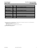
Host-Based Controller Modem AT Command Set 1998 Data Addendum June 15, AT Command Summary The following tables summarize the commands implemented by the modem. Commands may be executed when the modem is in COMMAND mode.
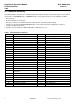
Data Addendum June 15, 1998 AT Command Summary (continued) Host-Based Controller Modem AT Command Set Table 2. AT Testing and Debugging Command Set Summary Command &&C &&L &&R &&S Description Write to/read from host interface Line-to-line loopback Write to/read from DSP RAM location Speaker codec loopback Command %T94 %T124 %T125 #UD Description Test external DSP RAM Return to on-chip DSP RAM Load K56flex image to external DSP RAM Unimodem diagnostics Table 3.
Host-Based Controller Modem AT Command Set 1998 AT Command Summary (continued) Data Addendum June 15, Table 4.
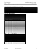
Data Addendum June 15, 1998 AT Command Summary (continued) Result Code CONNECT 29333 EC* CONNECT 30666 EC* CONNECT 33333 EC* CONNECT 34666 EC* CONNECT 37333 EC* CONNECT 38666 EC* CONNECT 41333 EC* CONNECT 42666 EC* CONNECT 45333 EC* CONNECT 46666 EC* CONNECT 49333 EC* CONNECT 50666 EC* CONNECT 53333 EC* CONNECT 54666 EC* Numeric 101 102 103 104 105 106 107 108 109 110 111 112 113 114 Host-Based Controller Modem AT Command Set Description Connection at 29333 bit/s (V.90 mode) Connection at 30666 bit/s (V.
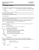
Host-Based Controller Modem AT Command Set 1998 Data Addendum June 15, AT Commands Reference AT commands are issued to the modem to control the modem's operation and software configuration. AT commands can only be entered while the modem is in command mode. The format for entering AT commands is: TYPE: ATXn where X is the AT command and n is the specific value for that command. PRESS: Enter If n is omitted from a command that takes a parameter valu, the value 0 I(zero) is assumed.
Data Addendum June 15, 1998 AT Command Reference (continued) Dn Host-Based Controller Modem AT Command Set Dial This command instructs the modem to begin the dialing sequence. The dial string (n, including modifiers and the telephone number) is entered after the ATD command. A dial string can be up to 60 characters long. Any digit or symbol (09, *, #, A, B, C, D) may be dialed as touchtone digits.
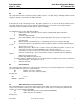
Host-Based Controller Modem AT Command Set AT Command Reference (continued) OK Data Addendum June 15, 1998 n=1 ERROR Hn Otherwise Hook Control This command instructs the modem to go on-hook to disconnect a call, or off-hook to make the phone line busy. H0: Modem goes on-hook (default). H1: Modem goes off-hook. Result Codes: OK n = 0, 1 ERROR Otherwise In Request ID Information This command displays specific product information about the modem.
Data Addendum June 15, 1998 AT Command Reference (continued) Host-Based Controller Modem AT Command Set The ATI11 result has two pages; the user must hit a key to get the second page. See the following example: ati11 Description K56flex connection V.90 Connection ---------------------------------------------1 Last Connection 56K V.
Host-Based Controller Modem AT Command Set AT Command Reference (continued) Data Addendum June 15, 1998 20. Reason for call ending, only valid after call ends: 0 = Local modem command: ATH, DTR drop 1 = Remote modem: cleardown, loss of signal 2 = No answer, busy, etc. 3 = Training failure V.90, K56flex or V.34. 4 = Protocol failure if required by \N4, for example. 21. For PCM connection only, a hexadecimal 6-bit pattern of T1 frames with robbed-bit signaling. 22.
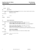
Data Addendum June 15, 1998 AT Command Reference (continued) On Host-Based Controller Modem AT Command Set Return On-line to Data Mode O0: O1: O3: Instructs the modem to exit on-line command mode and return to data mode (see AT Escape Sequence, +++). This command issues a retrain before returning to on-line data mode. This command issues a rate renegotiation before returning to on-line data mode.
Host-Based Controller Modem AT Command Set AT Command Reference (continued) Data Addendum June 15, 1998 Wn Result Code Option W0: W1: W2: Result Codes: OK ERROR CONNECT result code reports DTE receive speed. Disable protocol result codes. CONNECT result code reports DTE receive speed. Enable protocol result codes. CONNECT result code reports DCE receive speed. Enable protocol result codes (default).
Data Addendum June 15, 1998 AT Command Reference (continued) Host-Based Controller Modem AT Command Set Yn Long Space Disconnect Long space disconnect is always disabled. Y0: Disable long space disconnect (default). Y1: Enable long space disconnect (NOT SUPPORTED). Result Codes: OK n=0 ERROR Otherwise Zn Recall Stored Profile This command instructs the modem chip set to go on-hook and restore the profile saved by the last &W command. Either Z0 or Z1 restores the same single profile.
Host-Based Controller Modem AT Command Set AT Command Reference (continued) &Dn Data Addendum June 15, 1998 DTR Control This command interprets how the modem responds to the state of the DTR signal and changes to the DTR signal. &D0: Ignore. The modem ignores the true status of DTR and treats it as always on. This should only be used if your computer does not provide DTR to the modem.
Data Addendum June 15, 1998 AT Command Reference (continued) &Kn Host-Based Controller Modem AT Command Set Local Flow Control Selection &K0: Disable flow control &K1: Reserved &K2: Reserved &K3: Enable RTS/CTS (hardware) flow control (default) &K4: Enable XON/XOFF flow control Result Codes: OK n = 0, 3, 4 ERROR Otherwise &Mn &M0: &M1: &M2: &M3: &M4: Asynchronous Communications Mode Asynchronous mode (default).
Host-Based Controller Modem AT Command Set AT Command Reference (continued) &Sn Data Addendum June 15, 1998 Data Set Ready (DSR) Option This command selects DSR action. &S0: DSR always ON (default). &S1: DSR comes on when establishing a connection and goes off when the connection ends. Result Codes: OK ERROR &Tn n = 0, 1 Otherwise Self-Test Commands This command allows the user to perform diagnostic tests on the modem.
Data Addendum June 15, 1998 AT Command Reference (continued) &V Host-Based Controller Modem AT Command Set View Active Configuration and Stored Profile This command is used to display the active profiles.
Host-Based Controller Modem AT Command Set AT Command Reference (continued) Data Addendum June 15, 1998 &Wn Store Current Configuration This command stores certain command options and S-register values except S3, S4, and S5. The ATZ command or a power-up reset of the modem restores this profile.
Data Addendum June 15, 1998 AT Command Reference (continued) \J Host-Based Controller Modem AT Command Set Bits/s Rate Adjusted This command determines whether or not the negotiated connect speed of the modem forces the adjustment of the speed of the DTE to the modem’s speed. \J0: Buffer mode. Error control selected (or not) by \Nn command (default). \J1: Force the max DCE rate to the DTE rate.
Host-Based Controller Modem AT Command Set AT Command Reference (continued) Data Addendum June 15, 1998 \N3: V.42, MNP, or buffer (default). The modem attempts to connect in V.42 error control mode. If this fails, the modem attempts to connect in MNP mode. If this fails, the modem connects in buffer mode and continues operation. This is also known as V.42/MNP auto reliable mode (same as &Q5). \N4: V.42 or disconnect. The modem attempts to connect in V.42 error control mode.
Data Addendum June 15, 1998 AT Command Reference (continued) \Tn Host-Based Controller Modem AT Command Set Inactivity Timer This command specifies the length of time (in minutes) that the modem will wait before disconnecting when no data is sent or received. A setting of zero disables the timer. Alternatively, this timer may be specified in register S30. This function is only applicable to buffer mode. \T0: Inactivity timer disabled (default).
Host-Based Controller Modem AT Command Set AT Command Reference (continued) Data Addendum June 15, 1998 The table below shows the possible values: “AT-V90=X” 0 1 2 3 4 5 6 7 8 9 10 11 12 13 14 15 16 17 18 19 20 21 %B Downstream Rate V.
Data Addendum June 15, 1998 AT Command Reference (continued) Host-Based Controller Modem AT Command Set %Cn Data Compression Control This command determines the operation of V.42bis and MNP class 5 data compression. Online changes do not take effect until a disconnect occurs first. %C0: V.42bis/MNP 5 disabled. No data compression. %C1: V.42bis/MNP 5 enabled. Data compression enabled (default).
Host-Based Modem AT Command Set 1998 Data Addendum June 15, Test and Debug AT Commands The following commands are to be used for testing and debugging only and are not meant for general use. &&C Write to / Read from DSP Register AT&&C, writes the value to DSP register at location . AT&&C reads from location . &&L Line-to-Line Loopback This command provides a loopback for line-to-line.
Data Addendum June 15, 1998 Test and Debug AT Commands (continued) Host-Based Controller Modem AT Command Set The modem may generate a single line or multiple lines, based on modem capabilities and call results, followed by a standard OK final result code. For example, if call setup failed, only that result is useful.
Host-Based Modem AT Command Set Test and Debug AT Commands (continued) 41 42 43 44 45 46-4F 50 51 52 53 54 55 56 57 58 59 5A-5F 60 61 62-7F 80-FF 3 digits 2 digits 2 digits Table 8 4 digits 0-400 0-FF 0-FF 0-1 0-200 1 digit 1 digit 8 digits 8 digits 8 digits 8 digits 8 digits 8 digits 8 digits 8 digits 0-2 0-2 0-FFFFFFFF 0-FFFFFFFF 0-FFFF 0-FFFF 0-FFFFFFFF 0-FFFFFFFF 0-FFFF 0-FFFF Tables 9-10 2 digits Note 10 0-FF Data Addendum June 15, 1998 Error Control frame size Error control link timeouts Error
Data Addendum June 15, 1998 Test and Debug AT Commands (continued) Host-Based Controller Modem AT Command Set Table 7 - errorControl Active from 3.5.2/V.58 Value 0 1 2 3-7F 80 81 82 82-FF Description Disable/none V.42 LAPM V.42 Alternative protocol (MNP™) Reserved (V.58) MNP10™ ECP™ Enhanced Cellular Protocol ETC Reserved for mfgs Implemented X X X Table 8 - compressionActive from 3.2.2/V.58 Value 0 1 2-7F 80 81-FF Description None V.42bis Reserved (V.
Host-Based Modem AT Command Set Test and Debug AT Commands (continued) 2A 2B 2C 2D 2E 2F 30 31 32 33 34 3C 3D 3E 3F 40 41 42 46 47 50 51 52 5A 5B 5C 5D 5E 5F 60 64 28 CallAttemptsLimitExceeded ExtensionPhoneOffHook CallSetupFailTimerExpired IncomingCallDetected LoopCurrentInterrupted NoDialTone VoiceDetected ReorderTone SitTone EngagedTone LongSpaceDisconnect CarrierLost TrainingFailed NoModulationinCommon RetrainFailed RetrainAttemptCountExceeded GstnCleardownReceived FaxDetected InTestMode IntrusiveSelf
Host-Based Controller Modem AT Command Set Data Addendum June 15, 1998 AT Commands Reference S-Registers S-registers generally affect how the AT commands perform. Contents of the registers can be displayed or modified when the modem is in command mode. To display the value of an S-register: TYPE: ATSn? where n is the register number. PRESS: Enter To modify the value of an S-register: TYPE: ATSn = r where n is the register number, and r is the new register value.
Host-Based Controller Modem AT Command Set AT Commands Reference S-Registers (continued) S4 Data Addendum June 15, 1998 Response Formatting Character (user defined) This register determines the ASCII value used as the line feed character. The modem uses a line feed character in command mode when it responds to the computer. Range: 0—127, ASCII decimal Default: 10 (line feed) Units: ASCII Note: This register value is not stored with &W command.
Data Addendum June 15, 1998 AT Commands Reference S-Registers (continued) S8 Host-Based Controller Modem AT Command Set Comma Dial Modifier Time This register sets the time, in seconds, that the modem must pause when it encounters a comma (,) in the dial command string. Range: 0—65 Default: 2 Units: seconds S10 Automatic Disconnect Delay This register sets the length of time, in tenths of a second, that the modem waits before hanging up after a loss of carrier.
Host-Based Controller Modem AT Command Set AT Commands Reference S-Registers (continued) S21 Data Addendum June 15, 1998 V.24/General Bit Mapped Options Status Indicates the status of command options. Only bits 3, 4 and 5 are used, read-only.
Data Addendum June 15, 1998 AT Commands Reference S-Registers (continued) S30 Host-Based Controller Modem AT Command Set Inactivity Timer S30 specifies the length of time (in minutes) that the modem will wait before disconnecting when no data is sent or received. This function is only applicable to buffer mode.. Range: 0—255 Default: 0 S32 Synthetic Ring Volume This register specifies a synthetic ring volume.
Host-Based Controller Modem AT Command Set AT Commands Reference S-Registers (continued) S38 Data Addendum June 15, 1998 K56flex Downstream Rate To force a particular K56flex downstream rate, use S-register S38. S38=0 disables K56flex, and may allow a more reliable V.34 connection. S38=1 default allows the modem to select the downstream rate automatically. Other values of S38 force the downstream rate, with fallback to V.
Data Addendum June 15, 1998 AT Commands Reference S-Registers (continued) S43 Host-Based Controller Modem AT Command Set Auto Mode (default 1, range 01) This command is used for testing and debugging only. V.32bis startup auto mode operation disabled. 0 = auto mode disabled, 1 = enabled.
Host-Based Controller Modem AT Command Set Data Addendum June 15, 1998 AT FAX Command Set (Class 1 FAX) The Lucent Technologies modem supports FAX commands conforming to EIA standard 578. These commands are given here with short descriptions; complete explanations are given in the standard, available from the Electronic Industries Association. Table 5.
Host-Based Controller Modem AT Command Set 1998 Data Addendum June 15, AT FAX Commands Reference +FCLASS? Service Class Indication This command causes the modem to display the current setting. The modem can operate either as a Class 0 data modem or a class 1 FAX modem. Typical responses: +FCLASS? 000 if in data mode; 001 if in FAX class 1, 008 if in voice mode, and 080 if in VoiceView† mode. +FCLASS=? Service Class Capabilities This command causes the modem to display the classes it supports.
Host-Based Controller Modem AT Command Set AT Fax Commands Reference (continued) +FTM= Data Addendum June 15, 1998 Transmit FAX Data with Carrier This command causes the modem to transmit data at the modulation specified by . The following table shows the values you can enter for this command and the meaning of those values. Command Option +FRM= Modulation Speed (bits/s) +FTM=3 V.21 Channel 2 300 +FTM=24 V.27ter 2400 +FTM=48 V.27ter 4800 +FTM=72 V.29 7200 +FTM=96 V.
Data Addendum June 15, 1998 AT Fax Commands Reference (continued) +FTH= Host-Based Controller Modem AT Command Set Transmit HDLC Data with Carrier This command causes the modem to transmit data framed in the HDLC protocol at the modulation specified by . Command Option +FRH= Modulation Speed (bits/s) +FTH=3 V.21 Channel 2 300 +FTH=24 V.27ter 2400 +FTH=48 V.27ter 4800 +FTH=72 V.29 7200 +FTH=96 V.29 9600 +FTH=73 V.17 7200 +FTH=74 V.17 (short train) 7200 +FTH=97 V.
Host-Based Controller Modem AT Command Set AT Fax Commands Reference (continued) +FPR= Data Addendum June 15, 1998 Select Fax port rate This command sets the DTE to DCE fax port rate.
Data Addendum June 15, 1998 AT Fax Commands Reference (continued) +FAA Host-Based Controller Modem AT Command Set Adaptive answer A Service Class 1 Facsimile DCE may have the ability to answer as a data modem DCE or as a Facsimile DCE. It also may be able to adaptively change from Class 1 facsimile mode (•FCLASS•1.0) to data modem operation (•FCLASS•0) in response to the incoming call. The •FAA parameter controls this feature.
Host-Based Controller Modem AT Command Set Data Addendum June 15, 1998 AT Voice Command Set The AT Voice Command set follows a modified IS-101 architecture. The commands are sent through the comm port, but the data path is sent either through the comm port or through a DMA channel using the wave driver. Tables 1 and 2 show a summary of the AT Voice Command Set. Summary of the AT Voice Command Set Table 6.
Host-Based Controller Modem AT Command Set Data Addendum June 15, 1998 AT Voice Commands Reference AT+FCLASS=8 Enter Voice Mode The command AT+FCLASS=8 puts the modem in voice mode. Speakerphone and TAD modes are subsumed under the more general heading of voice mode, and use a particular subset of voice mode commands to implement their respective features and functions.
Host-Based Controller Modem AT Command Set AT Voice Commands Reference (continued) AT+VGR= Data Addendum June 15, 1998 Receive Gain Selection This command will enable the receive microphone gain control.
Data Addendum June 15, 1998 AT Voice Commands Reference (continued) Host-Based Controller Modem AT Command Set AT Commands: Speakerphone Operation AT+VLS=
Host-Based Controller Modem AT Command Set AT Voice Commands Reference (continued) AT+VLS=? Data Addendum June 15, 1998 Analog Source/Destination Selection and DTMF/Tone Reporting Requests for the modem's DTMF/Tone reporting capabilities are made using this command. For each system configuration in voice mode (i.e., speakerphone and answering machine), the modem reports the capabilities that are enabled for the configuration.
Data Addendum June 15, 1998 AT Voice Commands Reference (continued) AT+VRA= Host-Based Controller Modem AT Command Set Ringback Goes Away Timer The modem uses the ringback goes away timer when originating a call. This command sets this timer to the amount of time the modem shall wait between ringbacks before assuming that the remote station has gone off-hook. AT+VRA? AT+VRA=? Returns the current value. Returns the range of supported values.
Host-Based Controller Modem AT Command Set AT Voice Commands Reference (continued) Data Addendum June 15, 1998 AT Voice Command Set Not Defined In IS-101 Specifications S32 Synthetic Ring Volume This command will provide a synthetic ring volume in dB with an implied minus sign. The default = 10. S33 Synthetic Ring Frequency This command will provide a synthetic ring frequency. The valid values are 05, with 0 = disabled and 15 = five varying ring frequencies. The default = 0.
Data Addendum June 15, 1998 AT Voice Commands Reference (continued) Host-Based Controller Modem AT Command Set Voice Modem Command Examples The application issues AT commands to request actions by the modem, and the modem responds with standard TIA-602 result codes to tell the application that the requested action has been completed. Notes for Speakerphone Examples 1.
Host-Based Controller Modem AT Command Set AT Voice Commands Reference (continued) Data Addendum June 15, 1998 Example # 1: Initiating a speakerphone call (with phone muting during conversation) The speakerphone application is loaded. The modem is initially idle, in data mode. The user then decides to pick up the phone to place a speakerphone call. Picking up the phone should initiate the following chain of events. Command Description AT+FCLASS=8 The modem enters voice mode. OK DCE responds.
Data Addendum June 15, 1998 AT Voice Commands Reference (continued) Host-Based Controller Modem AT Command Set Example # 2: Initiating a stored number speakerphone call The speakerphone application is loaded. The modem is initially idle, in data mode. The user then decides to place a speakerphone call either by entering the number without going off-hook first or selecting a number previously stored in the application.
Host-Based Controller Modem AT Command Set AT Voice Commands Reference (continued) Data Addendum June 15, 1998 Example # 3: Answering a speakerphone call The speakerphone application is loaded. The modem is initially idle, in data mode. In this mode, the modem is always screening for incoming calls. Command Description RING DCE reports ringing from remote station. The user decides to pick-up the phone, which should initiate the following: AT+FCLASS=8 Modem enters voice mode. OK DCE responds.
Data Addendum June 15, 1998 AT Voice Commands Reference (continued) Host-Based Controller Modem AT Command Set Example # 5: Receiving an incoming data call in speakerphone or TAD mode and switching to data mode In this example, the sequence begins at the point of the user or telephone answering device (TAD) taking the speakerphone off-hook and detecting a data calling tone from the other end.
Host-Based Controller Modem AT Command Set AT Voice Commands Reference (continued) Data Addendum June 15, 1998 AT+VSD=128,0 DTE selects normal silence detection sensitivity, and a silence detection interval of 0 seconds. Disable silence detection. OK DCE responds. -R DCE detects another ring, and notifies DTE. AT+VLS=1 The modem answers the call. OK DCE is off-hook. The TAD next plays its greeting message, issues a beep, and records the caller's message.
Data Addendum June 15, 1998 AT Voice Commands Reference (continued) Host-Based Controller Modem AT Command Set Example # 8: Call screening & recording a message with TAD—using the wave driver to transmit and receive voice samples The TAD application is loaded. The modem is initially idle, in data mode (+FCLASS=0). Command Description RING DCE reports ringing from remote station. AT+FCLASS=8 The modem enters voice mode. OK DCE responds. AT+VGT=128 Set speaker volume to normal. OK DCE responds.
Host-Based Controller Modem AT Command Set Data Addendum June 15, 1998 AT DSVD Commands In order to use the DSVD without a local phone, a ring 3 application can be used to simulate the local phone. In the absence of such an application, the voice connection needs to be auto enabled. This is accomplished by the following DSVD custom AT commands: Command Description AT-SSE-OF AT-SSE-ON AT-SSE-AC Simulates virtual offhook event. Simulates virtual onhook event.
Host-Based Controller Modem AT Command Set 1998 Data Addendum June 15, V.25ter AT Commands The +GMx commands are required by the Microsoft PC98 specifications. Manufacturer Identification (+GMI?) Read Syntax: AT+GMI? Result: Lucent Data/Fax Lucent Data/Fax/Voice/VoiceView (depending on product) Version / Revision Information (+GMR?) Read Syntax: AT+GMR? Result: Lucent driver version number (e.g. 1.5.05) Modem Identification (+GMM?) Read Syntax: AT+GMM? Result: H.324 video-ready rev. 1.
Host-Based Controller Modem AT Command Set V.25ter AT Commands (continued) +A8I: +A8M= +A8A: 58 Coded CM or JM octet Refer to V.8 document for coding. 1 Indicates V.8 ANSam signal flags 0 Indicated no ANSam signal detected Lucent Technologies Inc. Data Addendum June 15, 1998 , , and This indication is used by an answering DCE, if +A8E, !=0, to indicate detection of a V.
Host-Based Controller Modem AT Command Set 1998 Data Addendum June 15, V.80 AT Commands The chip set supports the Synchronous Access Mode and most of the commands specified in V.80 standards. The commands are either AT commands issued in the command mode, or in-band commands transmitted in the data stream. These in-band commands are delimited by the hexadecimal characters EM (or numerically, 19h.) A) Synchronous Access Mode AT commands Table 9. V.
Host-Based Controller Modem AT Command Set V.80 AT Commands (continued) Table 10. V.80 AT Commands (continued) Command Subparameters +ESA=[[,[,,,[,]]]] framed_idle Data Addendum June 15, 1998 Values Description 0 In transparent submode, DCE transmits marks (ones) on idle. 0 In Framed submode, DCE transmits HDLC flags on idle. 1 In Framed submode, DCE transmits marks (ones) on idle.
Host-Based Controller Modem AT Command Set Data Addendum June 15, 1998 AT Commands for Homologation Testing and Debugging This section lists the homologation testing and debugging commands and homologation parameter values for different countries. Table 11.
Host-Based Controller Modem AT Command Set AT Commands for Homologation Testing and Debugging (continued) Data Addendum June 15, 1998 Table 11. The Homologation Testing and Debugging Commands (continued) Name Description %Txx V.22 1200 originate signaling V.22 1200 answer signaling V.22bis/V.34 2400 originate signaling* V.22bis/V.34 2400 answer signaling* V.32/V.34 4800 originate signaling* V.32/V.34 4800 answer signaling* V.32/V.34 7200 originate signaling* V.32/V.34 7200 answer signaling* V.32bis/V.
Data Addendum Host-Based Controller Modem June 15, 1998 AT Command Set AT Commands for Homologation Testing and Debugging (continued) Configuring for Different Countries To configure for a specific country, execute the following AT commands: AT%T19,0,country_code in HEX (refer to Table 2) Verify with the ATI9 command (which displays the country name) that the right country has been configured. Table 12.
Host-Based Controller Modem AT Command Set AT Commands for Homologation Testing and Debugging (continued) Data Addendum June 15, 1998 Modifying Homologation Parameters Once the modem is configured for a country, the homologation parameters shown in Table 3 can be temporarily altered for that country with the following AT command AT%T21,par#,param_value where par# and param_value should be entered in HEX. For example, AT%T21,7,28 sets the call progress threshold to -40 dB.
Data Addendum Host-Based Controller Modem June 15, 1998 AT Command Set AT Commands for Homologation Testing and Debugging (continued) Homologation Parameters Table 13. The Homologation Parameters Par # Parameter Description Range Reference 1 Pulse dial make time 0—255 ATD 2 Pulse dial break time 0—255 ATD 3 Pulse dial digit pattern ATD 4 DTMF high tone level in dB with implied minus sign 1 = normal, 2 = Sweden, 3 = Norway 0—255 5 Min. DTMF dial speed in ms 0—255 S11 6 Max.
Host-Based Controller Modem AT Command Set AT Commands for Homologation Testing and Debugging (continued) Data Addendum June 15, 1998 Table 13.
Data Addendum Host-Based Controller Modem June 15, 1998 AT Command Set AT Commands for Homologation Testing and Debugging (continued) Table 13.
Host-Based Controller Modem AT Command Set AT Commands for Homologation Testing and Debugging (continued) Par # Parameter Description 4b Mercury register CIOCA LSB value—hybrid, impedance, etc.
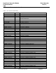
Data Addendum Host-Based Controller Modem June 15, 1998 AT Command Set AT Commands for Homologation Testing and Debugging (continued) Country Specific Homologation Parameters Country specific values for the homologation parameters are shown in Table 14. Note: The values listed in Table 14 are typical values and change based on OEM preferences. Table 14. The Country Specific Homologation Parameters Par. # 1 2 3 4 5 6 7 8 9 a b c d e f 10 11 12 13 14 15 16 17 18 19 1a 1b 1c 1d 1e 1f 20 21 22 23 Version 1.
Host-Based Controller Modem AT Command Set AT Commands for Homologation Testing and Debugging (continued) Data Addendum June 15, 1998 Table 15. The Country Specific Homologation Parameters (continued) Par.
Data Addendum Host-Based Controller Modem June 15, 1998 AT Command Set AT Commands for Homologation Testing and Debugging (continued) Par. # 4d 4e 4f Version 1.0 NA 0x1e 0x13 0xcd Australia 0x17 0x13 0xcd Belgium 0x1e 0x13 0xcd Denmark 0x1e 0x13 0xcd Lucent Technologies Inc.
Host-Based Controller Modem AT Command Set AT Commands for Homologation Testing and Debugging (continued) Data Addendum June 15, 1998 Table 15. The Country Specific Homologation Parameters (continued) Par. # 72 1 Netherlands 40 Italy 41 New Zeal.
Data Addendum Host-Based Controller Modem June 15, 1998 AT Command Set AT Commands for Homologation Testing and Debugging (continued) Table 15. The Country Specific Homologation Parameters (continued) Par. # 24 Netherlands 0 Italy 2 New Zeal.
Host-Based Controller Modem AT Command Set AT Commands for Homologation Testing and Debugging (continued) Par. # 74 Data Addendum June 15, 1998 4a Netherlands 0x00 Italy 0x00 New Zeal. 0x00 Norway 0x00 Spain 0x00 Sweden 0x00 Switzerland 0x00 4b 0x0c 0x0c 0x0c 0x0c 0x0c 0x0c 0x06 4c 0x6b 0x6b 0x6b 0x6b 0x6b 0x6b 0x6b 4d 0x1e 0x1e 0x16 0x1e 0x1e 0x16 0x17 4e 0x13 0x13 0x13 0x13 0x13 0x13 0x13 4f 0xcd 0xcd 0xcd 0xcd 0xcd 0xcd 0xcd Lucent Technologies Inc.
Data Addendum Host-Based Controller Modem June 15, 1998 AT Command Set AT Commands for Homologation Testing and Debugging (continued) Table 15. The Country Specific Homologation Parameters (continued) Par.
Host-Based Controller Modem AT Command Set AT Commands for Homologation Testing and Debugging (continued) Data Addendum June 15, 1998 Table 15. The Country Specific Homologation Parameters (continued) Par.
Data Addendum Host-Based Controller Modem June 15, 1998 AT Command Set AT Commands for Homologation Testing and Debugging (continued) Par. # 4c UK 0x6b Austria 0x6b Japan 0x6b China 0x6b Korea 0x6b Malaysia 0x6b Singapore 0x6b 4d 0x17 0x1e 0x1e 0x1e 0x1e 0x1e 0x1e 4e 0x13 0x13 0x13 0x13 0x13 0x13 0x13 4f 0xcd 0xcd 0xcd 0xcd 0xcd 0xcd 0xcd Version 1.0 Lucent Technologies Inc.
Host-Based Controller Modem AT Command Set AT Commands for Homologation Testing and Debugging (continued) Data Addendum June 15, 1998 Table 15. The Country Specific Homologation Parameters (continued) Par.
Data Addendum Host-Based Controller Modem June 15, 1998 AT Command Set AT Commands for Homologation Testing and Debugging (continued) Table 15. The Country Specific Homologation Parameters (continued) Par.
Host-Based Controller Modem AT Command Set AT Commands for Homologation Testing and Debugging (continued) Par. # 80 Data Addendum June 15, 1998 49 Taiwan 0x10 Thailand 0x10 Indonesia 0x10 Ireland 0x12 Portugal 0x10 Hong Kong 0x10 4a 0x00 0x00 0x00 0x00 0x00 0x00 4b 0x0c 0x0c 0x0c 0x06 0x0c 0x0c 4c 0x6b 0x6b 0x6b 0x6b 0x6b 0x6b 4d 4e 0x1e 0x1e 0x1e 0x17 0x1e 0x1e 0x13 0x13 0x13 0x13 0x13 0x13 4f 0xcd 0xcd 0xcd 0xcd 0xcd 0xcd Lucent Technologies Inc.
Data Addendum Host-Based Controller Modem June 15, 1998 AT Command Set AT Commands for Homologation Testing and Debugging (continued) Table 15. The Country Specific Homologation Parameters (continued) Par.
Host-Based Controller Modem AT Command Set AT Commands for Homologation Testing and Debugging (continued) Data Addendum June 15, 1998 Table 15. The Country Specific Homologation Parameters (continued) Par.
Data Addendum Host-Based Controller Modem June 15, 1998 AT Command Set AT Commands for Homologation Testing and Debugging (continued) Par. # 49 Canada 0 Mexico 0x10 India 0x10 Vietnam 0x10 Philippines 0x10 4a 0x88 0x00 0x00 0x00 0x00 4b 0x80 0x0c 0x0c 0x0c 0x0c 4c 0x6b 0x6b 0x6b 0x6b 0x6b 4d 4e 0x1e 0x1e 0x1e 0x1e 0x1e 0x13 0x13 0x13 0x13 0x13 4f 0xcd 0xcd 0xcd 0xcd 0xcd Version 1.0 Lucent Technologies Inc.
Host-Based Controller Modem AT Command Set AT Commands for Homologation Testing and Debugging (continued) Data Addendum June 15, 1998 Country Specific S Register Defaults Note: The values listed in Table 15 are typical values and change based on OEM preferences. Table 156. Country Specific Defaults for S Registers S Reg.
Data Addendum Host-Based Controller Modem June 15, 1998 AT Command Set AT Commands for Homologation Testing and Debugging (continued) Table 16. Country Specific Defaults for S Registers (continued) S Reg.
Host-Based Controller Modem AT Command Set AT Commands for Homologation Testing and Debugging (continued) Data Addendum June 15, 1998 Changing the DTMF Dial Speed Default Value To change the DTMF dial speed default value, follow these steps: 1. Set par# 5 (Min DTMF dial speed) and par# 6 (Max DTMF dial speed) to the required DTMF dial speed with the AT%T21 command. 2. Issue an ATZ command. 3. Issue an ATS11? command to display the new value.
For additional information, contact your Microelectronics Group Account Manager or the following: INTERNET: http://www.lucent.com/micro U.S.A.: Microelectronics Group, Lucent Technologies Inc., 555 Union Boulevard, Room 30L-15P-BA, Allentown, PA 18103 1-800-372-2447, FAX 610-712-4106 (In CANADA: 1-800-553-2448, FAX 610-712-4106), e-mail docmaster@micro.lucent.com ASIA PACIFIC: Microelectronics Group, Lucent Technologies Singapore Pte. Ltd., 77 Science Park Drive, #03-18 Cintech III, Singapore 118256 Tel.