Lucent Technologies Installation Guide Cajun P118SX/LX STACKABLE ETHERNET SWITCH Cat No. 130010 Rev.
Preface Important information SAFETY PRECAUTIONS CAUTION – TO REDUCE THE RISK OF ELECTRIC SHOCK AND FIRE 1. All servicing should be undertaken ONLY by qualified personnel. The parts inside the unit CANNOT be serviced or repaired by the end user. Please call your service representative for assistance. 2. Do NOT plug in, turn on or attempt to operate a damaged unit. 3. Ensure that the chassis ventilation slots in the unit are NOT BLOCKED. 4.
Preface Safety Instructions 4. Austauschen einer durchgebrannten Sicherung NUR mit der gleichen Sorte und Belastbarkeit wie sie auf der Sicherheitsaufschrift markiert ist. Die Aufschrift befindet sich neben der Stromzufuhr wo sich auch der Sicherungskasten befindet. 5. Bedienen Sie das Gerät NICHT an einer Stelle an der die Umgebungstemperatur 50ºC übersteigt. 6. Ziehen Sie das Netzkabel raus, BEVOR Sie versuchen die Hauptsicherung zu kontrollieren oder auszutauschen.
Preface Safety Instructions Regulatory Approvals and Safety Information for the Cajun P118SX/LX Products LASER SAFETY The Cajun P118SX multi-mode transceiver and the Cajun P118LX single mode transceiver are a Class 1 laser product. They comply with IEC 825-1 and Food and Drug Administration (FDA) 21 CFR 1040.10 and 1040.11. The transceivers must be operated under recommended operating conditions. LASER CLASSIFICATION Class 1 lasers are inherently safe under reasonably foreseeable conditions of operation.
Chapter 1 Overview This guide is divided into the following main sections: Overview: A general description of the features of the Cajun™ P118. Installation: Instructions for getting the Cajun P118 and Cajun P110 stack up and running.
Chapter 1 Overview Description The Cajun P118SX and P118LX are part of the Cajun P110 family of switches. The Cajun P110 family is composed of high-performance stackable switches which may be used singly or stacked in any combination. The Cajun P118 has eight Ethernet/Fast Ethernet (10/100BASE-T) ports and two Gigabit Ethernet (1000BASE-X) ports.
Chapter 2 Preliminary Settings Fiber Optic Specifications Two auto-negotiation 1000Base-X ports. P118SX 1000Base-SX ports 220m over 62.5 µm MMF or 550m over 50 µm MMF. P118LX 1000Base-LX ports 5 km over SMF or 550m over MMF with special patch cord.
Chapter 2 Installation Default Values Note: The management-set default values are those defined in Cajun P110 NMA agent version 8.6. If you download or install a later version of the agent software, please refer to the Cajun P110 NMA Release Notes for any changes. Before you install the Cajun P118, check Table 1 which shows the default values for key parameters and how you can change them.
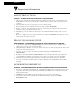
Chapter 2 Setting Installation the DIP switches First, set the DIP switches. The position of the switches depends on the Cajun P110 application. The drawing below shows the default positions of the DIP switches on the rear panel of the Cajun P110 switch. Figure 1 The Cajun P118 Rear Panel Showing the DIP Switches in Their Default Positions TAG 2 AUTO-NEG.2 TAG 1 AUTO-NEG.
Chapter 2 Installation TAG 1, TAG 2 –802.1Q VLAN Tagging mode (TAG 1 is for port 1 and TAG 2 is for port 2). VLAN Tagging transfers across the backbone packets with VLAN and priority. By carrying this information across the inter-switch link, VLAN Tagging makes it possible to distribute VLANs across the organization. This tagging facility allows you to make two 802.1Q-compliant hubs act as a single logical device. - ON: IEEE 802.1Q VLAN Tagging is enabled.
Chapter 2 Installation Installing the Cajun P118 The procedure for getting the Cajun P118 up and running depends on whether the switch is to operate standalone or as part of a stack. First, attach the adhesive rubber legs to the base of the Cajun P110 switch. If the switch is to be rack mounted, do not attach the legs. Standalone Operation - Plug ‘n’ Play Getting the Cajun P110 switch working is quick and easy: 1. Connect the power cable to the switch. 2. Connect the cables to the front panel ports.
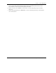
Chapter 2 Installation 6. Connect Cajun P110 switches using the Exoplane cables, as shown in Figure 2. A switch connects to its upper neighbor through two Exoplane cable, and to its lower neighbor through another two Exoplane cables. Make sure you securely fasten the cables to the connectors. Cabling Requirements: For correct operation, the Cajun P110 Exoplane must be fully connected, with all units powered up.
Chapter 2 Installation Notes: 10 If Cajun P110 NMA in the stack contains the software version 8.6 or higher (as specified in the Cajun P118 Release Notes) or higher, the stack is now fully operational When a new version of agent software becomes available, you should perform software download to benefit from the extra capabilities provided. Please refer to the Cajun P110 NMA Installation Guide for details.
Chapter 2 Installation Rack Mounting Cajun P110 switches slot into a standard 19 inch rack. Remove the rubber legs from the base of any switch that is to be rack mounted. Place the switches in the rack, and then connect the Exoplane, as follows: 1. Snap open the ends of the front panel to reveal the fixing holes. 2. Slot the switch into the rack. Insert the switches into the rack so that the switches in a logical stack lie directly on top of each other.
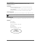
Chapter 2 Installation Diagnostics Table 3 and Table 4 explain the meaning of the Cajun P118 diagnostic LED indicators. Button Figure 4 The Cajun P118 Front Panel LEDs and Buttons Table 3 Meaning of the Cajun P118 Front Panel Buttons Function Meaning Select The buttons determine what function will be displayed by the 18 Port LEDs (the top two rows of LEDs). The seven Function LEDs (above the Select buttons) show which function is currently displayed by the Port LEDs.
Chapter 2 Table 4 Installation Meaning of the Cajun P118 front panel LEDs LED Indicator Function Status Meaning PWR Power OFF ON Blink Mains power not connected Mains power connected Working on back-up power supply NMA Agent OFF ON No agent in switch Switch contains an active agent RED NMA N/A 3RUW /(' Function LED /LQN VWDWXV 2)) 21 Blink once Blink twice 3RUW 'LVDEOHG 3RUW LV HQDEOHG DQG OLQN LV 2. Link Test Fail. 1 Partition .
Lucent Technologies Inc., 'DWD 1HWZRUNLQJ 6\VWHPV 0W $LU\ 5G %DVNLQJ 5LGJH NJ 07920. Cajun and CajunView are trademarks, and in some jurisdictions may be registered trademarks of Lucent Technologies or its affiliated companies. Other trademarks appearing in this document are the property of their respective owners. © Copyright 1998 Lucent Technologies. All rights reserved.