Information Manual, Rev. 1 September 1999 Evaluation Kit for USS-720 Instant USB™ USB-to-IEEE* 1284 Bridge Introduction The Lucent Technologies Microelectronics Group USS-720 Evaluation Kit is an assembly of all the peripheralrelated hardware, software, and documentation necessary to evaluate the USS-720 device and begin development efforts.
Evaluation Kit for USS-720 Instant USB USB-to-IEEE 1284 Bridge Information Manual, Rev. 1 September 1999 Table of Contents Evaluation Kit for USS-720 Instant USB USB-to-IEEE 1284 Bridge Introduction ............ 1-1 Introduction .......................................................................................................................................................... 1-1 Evaluation Kit Contents ..................................................................................................
Information Manual, Rev. 1 September 1999 Evaluation Kit for USS-720 Instant USB USB-to-IEEE 1284 Bridge Table of Contents (continued) USS-720 Instant USB USB-to-IEEE 1284 Bridge Preliminary Data Sheet......................... 5-1 Features .............................................................................................................................................................. 5-1 Description ...............................................................................................
Evaluation Kit for USS-720 Instant USB USB-to-IEEE 1284 Bridge Information Manual, Rev. 1 September 1999 Table of Contents (continued) nFault Interrupt .................................................................................................................................... 5-23 Bulk In Interrupt ................................................................................................................................... 5-23 Bulk Out Interrupt ..............................................
Information Manual, Rev. 1 September 1999 Evaluation Kit for USS-720 Instant USB USB-to-IEEE 1284 Bridge Table of Contents (continued) 4.20. IOCTL_SET_ALTSETTING ................................................................................................................ 7-29 4.21. IOCTL_SOFT_RESET........................................................................................................................ 7-30 5. I/O Control Data Structures ...................................................
Evaluation Kit for USS-720 Instant USB USB-to-IEEE 1284 Bridge Information Manual, Rev. 1 September 1999 Evaluation Kit Contents The Lucent Technologies USS-720 Evaluation Kit consists of the following components: 1.
Evaluation Kit for USS-720 Instant USB USB-to-IEEE 1284 Bridge Information Manual, Rev. 1 September 1999 Evaluation Kit Contents (continued) ■ ■ ■ \Win98: — USS720.INF — USS720.SYS — USS720CI.DLL — USS720IN.DLL — USS720MN.DLL \Win98\Debug — USS720.INF — USS720.SYS — USS720CI.DLL — USS720IN.DLL — USS720IO.
Evaluation Kit for USS-720 Instant USB USB-to-IEEE 1284 Bridge Information Manual, Rev. 1 September 1999 Getting Started Instructions An initial evaluation of the USS-720 device can be performed using the In-System Design USB Smart Cable (i.e., the Lucent USS-720-based USB printer cable), the above-mentioned required hardware, and software supplied on the 3 1/2 in. diskette included in this kit. The basic evaluation procedure consists of the following steps outlined below for OSR2.1 and Windows 98: OSR2.
Information Manual, Rev. 1 September 1999 Evaluation Kit for USS-720 Instant USB USB-to-IEEE 1284 Bridge Getting Started Instructions (continued) Windows 98 Cable Installation Instructions: 1. Connect the USB printer cable to a printer that is turned on and follow the instructions listed below. (Note that although it is not necessary to plug the USB printer cable into a printer to perform the following steps, the use of the printer provides a better demonstration of the USS-720 device's functionality.) 2.
Evaluation Kit for USS-720 Instant USB USB-to-IEEE 1284 Bridge Information Manual, Rev. 1 September 1999 To access software files from In-System Design’s home page, follow these steps: 1. Click on Drivers. 2. In the box labeled Library Name, type the library name: uss720_dev 3. Type the password for the library: usb_to_lpt (Note: Use all lower-case letters.) Notes for Developers Please note that the driver files in this evaluation kit are for evaluation purposes only.
Information Manual, Rev. 1 September 1999 Evaluation Kit for USS-720 Instant USB USB-to-IEEE 1284 Bridge Notes for Developers (continued) EEPROM Developers using the USS-720 must use an external serial EEPROM (or the equivalent) in their design and create their own hex data file for use in programming the EEPROM at their site. See the USS-720 data sheet and the glucent.zip file on the kit’s diskette for more information.
Evaluation Kit for USS-720 Instant USB USB-to-IEEE 1284 Bridge Information Manual, Rev. 1 September 1999 13 1-12 Lucent Technologies Inc.
September 1999 USB Applications Support Applications support for Lucent Technologies USS-720 Universal Serial Bus products can be obtained by contacting the following: Lucent Technologies Microelectronics Group 1247 S. Cedar Crest Blvd. Allentown, PA 18103 U.S.A. Phone: (610) 712-2947 FAX: (610) 712-2820, Attention: USB Applications Engineering e-mail: usb@lucent.
USB Applications Support September 1999 13 2-2 Lucent Technologies Inc.
February 1999 USS-720 Software Use Agreement Evaluation Kit Software Introduction In accordance with the license agreement that follows, your use of the software and other information furnished as part of the USS-720 Evaluation Kit is intended for uses in connection with evaluating and testing Lucent’s USS-720 device and beginning development efforts. In addition, subject to the license agreement, you may also distribute the software with the your USS-720 based peripheral.
USS-720 Software Use Agreement February 1999 USS-720 Driver Software (Object Code) License Agreement (continued) (c) LICENSEE may make those copies of LICENSED SOFTWARE necessary to the use by LICENSEE for which rights are granted hereunder, provided that each such copy contains any copyright and/or proprietary notice appearing on or in the LICENSED SOFTWARE being copied. (d) LICENSEE agrees that it will not use or copy LICENSED SOFTWARE except as authorized herein.
USS-720 Software Use Agreement February 1999 USS-720 Driver Software (Object Code) License Agreement (continued) ARTICLE II—FEES AND PAYMENTS 2.01 Fees LICENSEE shall, within thirty (30) days after execution of this Agreement by both parties and invoice by LUCENT, pay to LUCENT a fee of _________ for the rights granted herein. 2.
USS-720 Software Use Agreement February 1999 USS-720 Driver Software (Object Code) License Agreement (continued) ARTICLE IV—MISCELLANEOUS PROVISIONS 4.01 Agreement Prevails This agreement shall prevail notwithstanding any conflicting terms or legends which may appear on or in LICENSED SOFTWARE. 4.02 Warranty and Indemnity (a) LUCENT warrants that LICENSED SOFTWARE will be in good working order at the time it is furnished.
February 1999 USS-720 Software Use Agreement USS-720 Driver Software (Object Code) License Agreement (continued) (c) LICENSEE's obligations under this Section 4.
USS-720 Software Use Agreement February 1999 USS-720 Driver Software (Object Code) License Agreement (continued) 4.09 Applicable Law The construction and performance of this agreement shall be governed by the laws of the State of New York, U.S.A., excluding choice of law rules. 4.
USS-720 Software Use Agreement February 1999 USS-720 Driver Software (Object Code) License Agreement (continued) DEFINITIONS APPENDIX LUCENT DEVICE means the LUCENT USS720 device. LICENSEE means a customer of Lucent’s USS720 device using the LICENSED SOFTWARE.
USS-720 Software Use Agreement 3-8 February 1999 Lucent Technologies Inc.
Application Note, Rev. 1 February 1999 Incorporating Customer Data into USS-720 Evaluation Kit Software Using the Build Me One Utility Introduction Using the Build Me One utility found on In-System Design’s web site, the USS-720 Evaluation Kit software can be modified to include data specific to a customer’s USB peripheral.
Incorporating Customer Data into USS-720 Evaluation Kit Software Using the Build Me One Utility Customer-Defined Data Customer-defined data may be submitted to In-System Design using the Build Me One utility located on the InSystem Design web site. Access www.insystem.com; select the Drivers area and then the utility labeled “Build Me One.” The modification of the software requires the following strings to be provided by the customer: 1. 2. 3. 4. 5. 6.
Application Note, Rev. 1 February 1999 Incorporating Customer Data into USS-720 Evaluation Kit Software Using the Build Me One Utility Operating Systems Supported USBLPTx Ports This software runs in Windows 95, and Windows 98. Evaluation kit version of software: Windows 95 must actually be OSR2.1 version 1214, which contains the USB supplement and QFE. Each vendor who purchases the USB Smart Cable from InSystem Design must execute an agreement with Microsoft in order to distribute the USB supplement.
Incorporating Customer Data into USS-720 Evaluation Kit Software Using the Build Me One Utility Printer Types Supported The following printers have been thoroughly tested and are known to work with the USS-720 software. Some printers require bidirectional mode to be disabled. There are known to be some printers which do not work with the USB Smart Cable. This is often due to an incompatibility with the printer’s Windows driver.
Preliminary Data Sheet, Rev. 5 September 1999 USS-720 Instant USB™ USB-to-IEEE* 1284 Bridge Features Device Features: ■ Full compliance with the Universal Serial Bus Specification Revision 1.
USS-720 Instant USB USB-to-IEEE 1284 Bridge Preliminary Data Sheet, Rev. 5 September 1999 Table of Contents Contents Page Features ................................................................. 5-1 Description .............................................................. 5-1 Pin Information ....................................................... 5-3 Overview ..................................................................5-5 USB Port ................................................................
USS-720 Instant USB USB-to-IEEE 1284 Bridge Preliminary Data Sheet, Rev.
USS-720 Instant USB USB-to-IEEE 1284 Bridge Preliminary Data Sheet, Rev. 5 September 1999 Pin Information (continued) Table 1.
USS-720 Instant USB USB-to-IEEE 1284 Bridge Preliminary Data Sheet, Rev. 5 September 1999 Overview The USS-720 creates a bridge between one USB port and one IEEE 1284 enhanced parallel port. Internally, the USS-720 contains an integrated USB transceiver, a USB device controller (UDC) core, an IEEE 1284 core, integrated IEEE 1284 buffers, storage for USB configuration data, data buffers, and control logic to tie the blocks together.
USS-720 Instant USB USB-to-IEEE 1284 Bridge Preliminary Data Sheet, Rev. 5 September 1999 USB Port (continued) The format for the externally supplied data is as shown in Table 2. The addressing for the specified EEPROM device is word aligned, so the following restrictions are placed upon the starting locations for the configuration and string descriptors. ■ The configuration descriptor must start at word address 0x13 (byte address 0x26).
USS-720 Instant USB USB-to-IEEE 1284 Bridge Preliminary Data Sheet, Rev. 5 September 1999 USB Port (continued) Configuration Descriptor The USS-720 has one default configuration descriptor. This descriptor has one interface, which has three alternate settings. The three alternate settings and the endpoints that they support are shown in Table 4. Table 4.
USS-720 Instant USB USB-to-IEEE 1284 Bridge Preliminary Data Sheet, Rev. 5 September 1999 USB Port (continued) Interface Descriptors The USS-720 supports a single interface with three alternate settings. Interface 0, Alternate Setting 0 (I0:A0) Table 6.
USS-720 Instant USB USB-to-IEEE 1284 Bridge Preliminary Data Sheet, Rev. 5 September 1999 USB Port (continued) Interface 0, Alternate Setting 1 (I0:A1) Table 8. Interface Descriptor, I0:A1 Offset 0 1 2 3 4 5 6 7 8 Field bLength bDescriptorType bInterfaceNumber bAlternateSetting bNumEndpoints bInterfaceClass iInterfaceSubClass bInterfaceProtocol iInterface Size Byte Byte Byte Byte Byte Byte Byte Byte Byte Value 0x09 0x04 0x00 0x01 0x02 0x07 0x01 0x02 0x00 Description Size of this descriptor in bytes.
USS-720 Instant USB USB-to-IEEE 1284 Bridge Preliminary Data Sheet, Rev. 5 September 1999 USB Port (continued) Interface 0, Alternate Setting 2 (I0:A2) Table 11. Interface Descriptor, I0:A2 Offset 0 1 2 3 4 5 6 7 8 Field bLength bDescriptorType bInterfaceNumber bAlternateSetting bNumEndpoints bInterfaceClass iInterfaceSubClass bInterfaceProtocol iInterface Size Byte Byte Byte Byte Byte Byte Byte Byte Byte Value 0x09 0x04 0x00 0x02 0x03 0xFF 0x00 0xFF 0x00 Description Size of this descriptor in bytes.
USS-720 Instant USB USB-to-IEEE 1284 Bridge Preliminary Data Sheet, Rev. 5 September 1999 USB Port (continued) Pipes Four pipes are defined: Control, Bulk Out, Bulk In, and Interrupt. Control Pipe The Control pipe is the default pipe, used for USB setup and control packets. Its maximum packet size is 8 bytes. The Control pipe is also used for class- and vendor-specific commands that: ■ ■ Configure class- and vendor-specific features. Retrieve Device, Configuration, and String descriptors.
USS-720 Instant USB USB-to-IEEE 1284 Bridge Preliminary Data Sheet, Rev. 5 September 1999 USB Port (continued) Printer Class-Specific Requests Printer class-specific requests supported by the USS-720 are listed in Table 15. Table 15.
USS-720 Instant USB USB-to-IEEE 1284 Bridge Preliminary Data Sheet, Rev. 5 September 1999 USB Port (continued) Vendor-Specific Requests Vendor-specific requests supported by the USS-720. Table 17.
USS-720 Instant USB USB-to-IEEE 1284 Bridge IEEE 1284 Port The IEEE 1284 port on the USS-720 is compliant with the IEEE 1284-1994 standard. The parallel port operates in two distinct modes. In fully Automatic Mode, the IEEE 1284 protocol is implemented completely in hardware. Compatibility Mode, Nibble Mode, and ECP Mode (with or without RLE compression) are supported, with all negotiation, termination, and other features of the protocol handled transparently by the hardware.
USS-720 Instant USB USB-to-IEEE 1284 Bridge Preliminary Data Sheet, Rev. 5 September 1999 IEEE 1284 Port (continued) Registers Nine parallel port registers are available to the host. They are read and written using the GET_1284_REGISTER and SET_1284_REGISTER vendor-specific commands described above. The SET_1284_REGISTER writes a value into a particular register. Writes may either affect the configuration of the hardware or have a direct effect on parallel port control lines.
USS-720 Instant USB USB-to-IEEE 1284 Bridge Preliminary Data Sheet, Rev. 5 September 1999 IEEE 1284 Port (continued) Data Register Table 21. Data Register Data Register Bit Symbol Access Default 7 D7 R/W 0 6 D6 R/W 0 5 D5 R/W 0 Address: 0 4 D4 R/W 0 3 D3 R/W 0 2 D2 R/W 0 1 D1 R/W 0 0 D0 R/W 0 Bit Symbol Bit Description 7—0 D7—D0 Data. This register is equivalent to and operates in the same manner as the Data Register in a standard host-side parallel port controller chip.
USS-720 Instant USB USB-to-IEEE 1284 Bridge Preliminary Data Sheet, Rev. 5 September 1999 IEEE 1284 Port (continued) Control Register Table 23. Control Register Control Register Address: 2 Bit 7 6 5 4 3 2 1 0 Symbol HLH EPP mask Direction Int enbl SelectIn nInit AutoFd Strobe Access R/W R/W R/W R/W R/W R/W R/W R/W Default 0 1 0 0 1 1 0 0 Bit 7 6 5 4 3 2 1 0 Symbol Bit Description HLH Host Logic High. The parallel port HLH signal.
USS-720 Instant USB USB-to-IEEE 1284 Bridge Preliminary Data Sheet, Rev. 5 September 1999 IEEE 1284 Port (continued) EPP Address Register Table 24. EPP Address Register EPP Address Register Address: 3 Bit 7 6 5 4 3 2 1 0 Symbol A7 A6 A5 A4 A3 A2 A1 A0 Access R/W R/W R/W R/W R/W R/W R/W R/W Default X X X X X X X X Bit Symbol Bit Description 7—0 A7—A0 EPP Address.
USS-720 Instant USB USB-to-IEEE 1284 Bridge Preliminary Data Sheet, Rev. 5 September 1999 IEEE 1284 Port (continued) ECP Command Register Table 26. ECP Command Register ECP Command Register Address: 5 Bit 7 6 5 4 3 2 1 0 Symbol C7 C6 C5 C4 C3 C2 C1 C0 Access Write Write Write Write Write Write Write Write Default X X X X X X X X Bit Symbol 7—0 C7—C0 Bit Description ECP Command.
USS-720 Instant USB USB-to-IEEE 1284 Bridge Preliminary Data Sheet, Rev. 5 September 1999 IEEE 1284 Port (continued) Extended Control Register Table 27. Extended Control Register Extended Control Register Address: 6 Bit 7 6 5 4 3 2 1 0 Symbol Mode[2] Mode[1] Mode[0] nAck interrupt nFault interrupt Bulk In interrupt Bulk In empty Bulk Out empty Access R/W R/W R/W Read Read Read Read Read Default 0 0 0 0 0 0 1 1 Bit 7—5 Symbol Bit Description Mode[2:0] Mode.
USS-720 Instant USB USB-to-IEEE 1284 Bridge Preliminary Data Sheet, Rev. 5 September 1999 IEEE 1284 Port (continued) USS-720 Control Register Table 28. USS-720 Control Register USS-720 Control Register Address: 7 Bit 7 6 5 4 3 2 1 0 Symbol Discon.
USS-720 Instant USB USB-to-IEEE 1284 Bridge Preliminary Data Sheet, Rev. 5 September 1999 IEEE 1284 Port (continued) USS-720 Setup Register Table 29.
USS-720 Instant USB USB-to-IEEE 1284 Bridge Preliminary Data Sheet, Rev. 5 September 1999 IEEE 1284 Port (continued) Interrupts The USS-720 can return interrupt status on the interrupt pipe. Interrupt status may be generated as a result of one of seven separately maskable conditions. Any interrupts that are pending will no longer be pending after a read operation. The individual conditions are described in the sections that follow.
USS-720 Instant USB USB-to-IEEE 1284 Bridge Preliminary Data Sheet, Rev. 5 September 1999 External Circuitry Requirements The USS-720 is intended to be a single-chip solution. As such, the USB transceiver and the IEEE 1284 buffers have been integrated on-chip. External requirements include a 3.3 V supply and a 1.5 kΩ ± 5% pull-up resistor for the DPLS pin. If the internal oscillator is used, a 12 MHz crystal along with bias capacitors are needed (see Figure 3).
USS-720 Instant USB USB-to-IEEE 1284 Bridge Preliminary Data Sheet, Rev. 5 September 1999 Filter Bypass Mode For embedded applications, the USS-720 IEEE 1284 port can be operated in Filter Bypass Mode. This mode disables digital filtering of the parallel port signals into the USS-720, providing a performance improvement. Note: Since digital filtering is disabled, the parallel port lines will be susceptible to noise. Do not use this mode when driving across a cable.
USS-720 Instant USB USB-to-IEEE 1284 Bridge Preliminary Data Sheet, Rev. 5 September 1999 Electrical Characteristics Table 31. dc Characteristics (TA = 0 °C to 70 °C, VDD = 3.3 V ± 0.3 V, VSS = 0 V.) Parameter Input Voltage: Low High Output Voltage: Low High Power Dissipation Power Supply Voltage Power Supply Current Symbol Test Conditions Min Typ Max Unit VIL VIH — — — 2.0 — — 0.8 — V V VOL VOH PD VDD, VDDA VDD5 — — 25 °C, VDD = 3.3 V — 5 V environment 3 V environment — — 2.4 1.65 3 4.
USS-720 Instant USB USB-to-IEEE 1284 Bridge Preliminary Data Sheet, Rev. 5 September 1999 Timing Characteristics ■ Timing is specified over the operating range from 0 °C to 70 °C ambient temperature, VDD = 3.0 V to 3.6 V, and VDD5 = 4.75 V to 5.25 V. ■ All timing is referenced from the rising edge of CLK_LO, with 70 pF output load. ■ Only DIO is required to meet these input setup and hold times for proper operation.
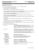
USS-720 Instant USB USB-to-IEEE 1284 Bridge Preliminary Data Sheet, Rev. 5 September 1999 Outline Diagram 44-Pin MQFP Dimensions are in millimeters. 13.20 ± 0.20 10.00 ± 0.20 1.60 REF PIN #1 IDENTIFIER ZONE 44 34 0.25 GAGE PLANE 1 33 SEATING PLANE 0.73/1.03 13.20 ± 0.20 10.00 ± 0.20 11 DETAIL A 23 0.130/0.230 12 22 0.30/0.45 0.20 DETAIL A DETAIL B 2.35 MAX 0.80 TYP M 1.95/2.10 DETAIL B SEATING PLANE 0.10 0.25 MAX 5-2111.
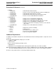
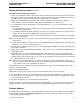
Application Note February 1999 Typical Circuit Showing the USS-720 Bridging USB to Parallel Port Description The USS-720 can be used in a variety of applications, such as bus-powered devices, self-powered devices, hubs, and embedded printer controllers. The following describes using the device in a buspowered application (see attached schematic). Note: The attached schematic depicts a typical functional circuit using the USS-720 as a bridge between the USB and a parallel port.
Typical Circuit Showing the USS-720 Bridging USB to Parallel Port Description (continued) Whenever device descriptor data is requested, the USS-720 drives both control pins CS (pin 35, Serial ROM Chip Select) and SK (pin 34, Serial ROM Clock). The USS-720 then looks for a response on DIO (pin 36, Serial ROM Data Signal). If there is no external device connected, and no data is present on the DIO pin, then the descriptor data is taken from the internal ROM.
1 19 20 21 22 23 24 25 26 27 28 29 30 31 32 33 34 35 36 A nSELECTIN nFAULT nINIT 1 2 3 4 5 6 7 8 9 10 11 12 13 14 15 16 17 18 nSTROBE Data_0 Data_1 Data_2 Data_3 Data_4 Data_5 Data_6 Data_7 nACK BUSY PError SELECT nAUTOFD CONNECTOR CENT36 J1 PLH PLH R7 R6 R5 R4 R3 R2 R1 2 3 4 Sufficient grounding must be implemented on the board to ensure proper functionality. A 4-layer board design is recommended with two layers for power and ground planes.
Typical Circuit Showing the USS-720 Bridging USB to Parallel Port 6-4 Application Note February 1999 Lucent Technologies Inc.
Preliminary User Guide, Rev. 2 February 1999 USS-720 USB Device Driver 1 Introduction This document describes the design and implementation of USS720.SYS, a Windows* WDM USB driver developed by In-System Design, Inc. (Note that this driver was written specifically to work with the InSystem Design USB Smart Cable. For vendorspecific implementations, refer to the “Notes for Developers” in the Introduction of this Information Manual.) The purpose of USS720.
USS-720 USB Device Driver Preliminary User Guide, Rev. 2 February 1999 Table of Contents Contents Page 1. Introduction ...................................................................................................................................................... 7-1 2. Initialization ...................................................................................................................................................... 7-3 3. I/O File Functions .......................................
Preliminary User Guide, Rev. 2 February 1999 USS-720 USB Device Driver 2 Initialization ■ The driver entry routine is called and initializes callbacks for the following functions when the operating system loads the driver: — Create: Open a handle to a device instance. — Read: Read a block of data from the Bulk In pipe. — Write: Write a block of data to the Bulk Out pipe. — DeviceIoControl: Process I/O requests documented in Section 4 of this document. — Close: Close the handle of the device instance.
USS-720 USB Device Driver Preliminary User Guide, Rev. 2 February 1999 3 I/O File Functions (continued) 3.1 CreateFile The CreateFile I/O file function opens an instance of a particular device and returns an open handle to the device instance. Details regarding the syntax, parameters, return values, and error codes are listed below. 3.1.
Preliminary User Guide, Rev. 2 February 1999 USS-720 USB Device Driver 3 I/O File Functions (continued) 3.2 ReadFile The ReadFile I/O file function reads data from the Bulk In pipe and returns TRUE if the function is successful and FALSE if it fails. Details regarding the syntax, parameters, return values, and error codes are listed below. 3.2.1 Syntax BOOL ReadFile( HANDLE LPVOID DWORD LPDWORD LPOVERLAPPED ); hDev, lpBuffer, nNumberOfBytesToRead, lpNumberOfBytesRead, lpOverlapped 3.2.
USS-720 USB Device Driver Preliminary User Guide, Rev. 2 February 1999 3 I/O File Functions (continued) 3.3 WriteFile The WriteFile I/O file function writes data to the Bulk Out pipe and returns TRUE if the function is successful and FALSE if it fails. Details regarding the syntax, parameters, return values, and error codes are listed below. 3.3.1 Syntax BOOL WriteFile( HANDLE LPVOID DWORD LPDWORD LPOVERLAPPED ); hDev, lpBuffer, nNumberOfBytesToWrite, lpNumberOfBytesWritten, lpOverlapped 3.3.
Preliminary User Guide, Rev. 2 February 1999 USS-720 USB Device Driver 3 I/O File Functions (continued) 3.4 DeviceIoControl The DeviceIoControl I/O file function sends a control code to a device instance and returns TRUE if the function is successful and FALSE if it fails. Details regarding the syntax, parameters, return values, and error codes are listed below. 3.4.
USS-720 USB Device Driver Preliminary User Guide, Rev. 2 February 1999 3 I/O File Functions (continued) 3.4.5 Error Codes ERROR_DEVICE_REMOVE—The device instance has been removed. ERROR_DEVICE_STOP—The device instance has been stopped. STATUS_INVALID_PARAMETER—Control Code is either invalid for this device instance or the device instance is in a state that cannot process the Control Code. See specific Control Code for other errors (see Section 4 of this document). 3.
Preliminary User Guide, Rev. 2 February 1999 USS-720 USB Device Driver 4 I/O Control Codes This section provides information for the I/O control codes used in the DeviceIoControl file function (see Section 3.4). These control codes are used in the DeviceIoControl function to perform any of the following devicespecific operations. Note: Refer to the header file included on the USS-720 Evaluation Kit diskette for details regarding these control codes definitions.
USS-720 USB Device Driver Preliminary User Guide, Rev. 2 February 1999 4 I/O Control Codes (continued) 4.1 IOCTL_1284_ ECP_FWDTOREV IOCTL_1284_ECP_FWDTOREV negotiates the peripheral from forward idle to reverse while in ECP register mode. Details regarding parameters and error codes follow. 4.1.1 Parameters lpInBuffer—Points to an input buffer. Not used with this operation. Set to NULL. nInBufferSize—Specifies the size (in bytes) of the buffer pointed to by lpInBuffer. Not used with this operation.
Preliminary User Guide, Rev. 2 February 1999 USS-720 USB Device Driver 4 I/O Control Codes (continued) 4.2 IOCTL_1284_ECP_REVTOFWD IOCTL_1284_ECP_REVTOFWD negotiates the peripheral from reverse to forward idle while in ECP register mode. Details regarding parameters and error codes follow. 4.2.1 Parameters lpInBuffer—Points to an input buffer. Not used with this operation. Set to NULL. nInBufferSize—Specifies the size (in bytes) of the buffer pointed to by lpInBuffer. Not used with this operation.
USS-720 USB Device Driver Preliminary User Guide, Rev. 2 February 1999 4 I/O Control Codes (continued) 4.3 IOCTL_1284_ ECP_SET_CHANNEL IOCTL_1284_ ECP_SET_CHANNEL sets the ECP channel on the peripheral for reads and writes. Details regarding parameters and error codes follow. 4.3.1 Parameters lpInBuffer—Points to a buffer that contains a single byte which specifies the ECP channel to be set. nInBufferSize—Specifies the size (in bytes) of the buffer pointed to by lpInBuffer.
Preliminary User Guide, Rev. 2 February 1999 USS-720 USB Device Driver 4 I/O Control Codes (continued) 4.4 IOCTL_1284_ SET_MODE IOCTL_1284_ SET_MODE negotiates the peripheral into one of the valid register modes. Details regarding parameters and error codes follow. 4.4.
USS-720 USB Device Driver Preliminary User Guide, Rev. 2 February 1999 4 I/O Control Codes (continued) 4.5 IOCTL_1284_ TERMINATE IOCTL_1284_ TERMINATE performs a standard 1284 termination sequence. Details regarding parameters and error codes follow. 4.5.1 Parameters lpInBuffer—Points to an input buffer. Not used with this operation. Set to NULL. nInBufferSize—Specifies the size (in bytes) of the buffer pointed to by lpInBuffer. Not used with this operation. Set to zero.
Preliminary User Guide, Rev. 2 February 1999 USS-720 USB Device Driver 4 I/O Control Codes (continued) 4.6 IOCTL_ABORT_PIPE IOCTL_ABORT_PIPE cancels any pending transfers for the specified pipe. The pipe state and endpoint state are unaffected. Details regarding parameters and error codes follow. 4.6.1 Parameters lpInBuffer—Points to a buffer that contains a single byte that specifies one of the following values: Value BULK_OUT_PIPE BULK_IN_PIPE INTERRUPT_PIPE Description Bulk Out pipe. Bulk In pipe.
USS-720 USB Device Driver Preliminary User Guide, Rev. 2 February 1999 4 I/O Control Codes (continued) 4.7 IOCTL_CANCEL_PIPE_REQUEST IOCTL_CANCEL_PIPE_REQUEST cancels the current request on the specified pipe by flushing the pipe and canceling any outstanding requests on the pipe. Details regarding parameters and error codes follow. 4.7.
Preliminary User Guide, Rev. 2 February 1999 USS-720 USB Device Driver 4 I/O Control Codes (continued) 4.8 IOCTL_GET_1284_REGISTER IOCTL_GET_1284_REGISTER returns all 1284 registers. Details regarding parameters and error codes follow. 4.8.1 Parameters lpInBuffer—Points to an input buffer that contains a byte that specifies the address of the parallel port register to be read. nInBufferSize—Specifies the size (in bytes) of the buffer pointed to by lpInBuffer.
USS-720 USB Device Driver Preliminary User Guide, Rev. 2 February 1999 4 I/O Control Codes (continued) 4.9 IOCTL_GET_ALTSETTING IOCTL_GET_ALTSETTING retrieves the current alternate interface setting from the USS-720 device. Details regarding parameters and error codes follow. 4.9.1 Parameters lpInBuffer—Points to an input buffer. Not used with this operation. Set to NULL. nInBufferSize—Specifies the size (in bytes) of the buffer pointed to by lpInBuffer. Not used with this operation. Set to zero.
Preliminary User Guide, Rev. 2 February 1999 USS-720 USB Device Driver 4 I/O Control Codes (continued) 4.10 IOCTL_GET_CAPABILITIES IOCTL_GET_CAPABILITIES returns a variable buffer length containing the device capabilities string. This is an IEEE 1284 compatible string. Details regarding parameters and error codes follow. 4.10.1 Parameters lpInBuffer—Points to an input buffer. Not used with this operation. Set to NULL. nInBufferSize—Specifies the size (in bytes) of the buffer pointed to by lpInBuffer.
USS-720 USB Device Driver Preliminary User Guide, Rev. 2 February 1999 4 I/O Control Codes (continued) 4.11 IOCTL_GET_CONFIGURATION_DESCRIPTOR IOCTL_GET_CONFIGURATION_DESCRIPTOR retrieves the current configuration descriptor. Details regarding parameters and error codes follow. 4.11.1 Parameters lpInBuffer—Points to an input buffer. Not used with this operation. Set to NULL. nInBufferSize—Specifies the size (in bytes) of the buffer pointed to by lpInBuffer. Not used with this operation. Set to zero.
Preliminary User Guide, Rev. 2 February 1999 USS-720 USB Device Driver 4 I/O Control Codes (continued) 4.12 IOCTL_GET_DEVICE_DESCRIPTOR IOCTL_GET_DEVICE_DESCRIPTOR retrieves the current device descriptor. Details regarding parameters and error codes follow. 4.12.1 Parameters lpInBuffer—Points to an input buffer. Not used with this operation. Set to NULL. nInBufferSize—Specifies the size (in bytes) of the buffer pointed to by lpInBuffer. Not used with this operation. Set to zero.
USS-720 USB Device Driver Preliminary User Guide, Rev. 2 February 1999 4 I/O Control Codes (continued) 4.13 IOCTL_GET_DEVICE_INSTANCES IOCTL_GET_DEVICE_INSTANCES returns a list of current devices based on the symbolic links created during each device enumeration. Details regarding parameters and error codes follow. 4.13.1 Parameters lpInBuffer—Points to an input buffer that will receive. Not used with this operation. Set to NULL.
Preliminary User Guide, Rev. 2 February 1999 USS-720 USB Device Driver 4 I/O Control Codes (continued) 4.14 IOCTL_GET_INTERFACE IOCTL_GET_INTERFACE gets the information about the current interface and pipes. Details regarding parameters and error codes follow. 4.14.1 Parameters lpInBuffer—Points to an input buffer. Not used with this operation. Set to NULL. nInBufferSize—Specifies the size (in bytes) of the buffer pointed to by lpInBuffer. Not used with this operation. Set to zero.
USS-720 USB Device Driver Preliminary User Guide, Rev. 2 February 1999 4 I/O Control Codes (continued) 4.15 IOCTL_GET_PORT_STATUS IOCTL_GET_PORT_STATUS returns a status byte. Details regarding parameters and error codes follow. 4.15.1 Parameters lpInBuffer—Points to an input buffer. Not used with this operation. Set to NULL. nInBufferSize—Specifies the size (in bytes) of the buffer pointed to by lpInBuffer. Not used with this operation. Set to zero.
Preliminary User Guide, Rev. 2 February 1999 USS-720 USB Device Driver 4 I/O Control Codes (continued) 4.16 IOCTL_ISSUE_USS720_COMMAND IOCTL_ISSUE_USS720_COMMAND issues a specific command for the USS-720 device. Details regarding parameters and error codes follow. 4.16.1 Parameters lpInBuffer—Points to an buffer that contains a single byte which specifies one of the following USS-720 commands: Command CMD_AUTOECP_ON CMD_AUTOECP_OFF CMD_COMPRESS_ON CMD_COMPRESS_OFF Description Turn Auto Mode on.
USS-720 USB Device Driver Preliminary User Guide, Rev. 2 February 1999 4 I/O Control Codes (continued) 4.17 IOCTL_READ_INTERRUPT_PIPE IOCTL_READ_INTERRUPT_PIPE reports changes on the parallel port and buffer status when they occur. Details regarding parameters and error codes follow. 4.17.1 Parameters lpInBuffer—Points to an input buffer. Not used with this operation. Set to NULL. nInBufferSize—Specifies the size (in bytes) of the buffer pointed to by lpInBuffer. Not used with this operation. Set to zero.
Preliminary User Guide, Rev. 2 February 1999 USS-720 USB Device Driver 4 I/O Control Codes (continued) 4.18 IOCTL_RESET_PIPE IOCTL_RESET_PIPE clears the halted state of the specified pipe within the USB stack and resets the stalled state of the endpoint on the device. Details regarding parameters and error codes follow. 4.18.
USS-720 USB Device Driver Preliminary User Guide, Rev. 2 February 1999 4 I/O Control Codes (continued) 4.19 IOCTL_SET_1284_REGISTER IOCTL_SET_1284_REGISTER sets one of the 1284 registers. Details regarding parameters and error codes follow. 4.19.1 Parameters lpInBuffer—Points to an input buffer that contains the following 2 bytes: Byte 0 1 Description Value to be written to the register. Address of the parallel port register.
Preliminary User Guide, Rev. 2 February 1999 USS-720 USB Device Driver 4 I/O Control Codes (continued) 4.20 IOCTL_SET_ALTSETTING IOCTL_SET_ALTSETTING sets the alternate interface setting. Details regarding parameters and error codes follow. 4.20.1 Parameters lpInBuffer—Points to an buffer that contains a single byte that specifies one of the following values: Value ALT_INTERFACE_0 ALT_INTERFACE_1 ALT_INTERFACE_2 Description Bulk Out pipe only. Bulk Out and Bulk In pipe.
USS-720 USB Device Driver Preliminary User Guide, Rev. 2 February 1999 4 I/O Control Codes (continued) 4.21 IOCTL_SOFT_RESET IOCTL_SOFT_RESET resets the device, flushes the Bulk Out and Bulk In pipes to the default states. Details regarding parameters and error codes follow. 4.21.1 Parameters lpInBuffer—Points to an input buffer. Not used with this operation. Set to NULL. nInBufferSize—Specifies the size (in bytes) of the buffer pointed to by lpInBuffer. Not used with this operation. Set to zero.
Preliminary User Guide, Rev. 2 February 1999 USS-720 USB Device Driver 5 I/O Control Data Structures This section describes the data structures used in I/O control codes. 5.1 DEVICE_INSTANCE_HEADER The DEVICE_INSTANCE_HEADER structure is used when issuing the IOCTL_GET_DEVICE_INSTANCES control code. 5.1.1 Data Structure typedef struct _DEVICE_INSTANCE_HEADER{ DWORD NumDeviceInstance; DWORD TotalLength; }DEVICE_INSTANCE_HEADER; 5.1.2 Members NumDeviceInstance—Total number of device instances.
USS-720 USB Device Driver Preliminary User Guide, Rev. 2 February 1999 5 I/O Control Data Structures (continued) 5.3 REGISTER_1284 The REGISTER_1284 structure is used when issuing the IOCTL_GET_1284_REGISTER control code. 5.3.
Preliminary User Guide, Rev. 2 February 1999 USS-720 USB Device Driver 5 I/O Control Data Structures (continued) 5.4 ADVREGISTER_1284 The ADVREGISTER_1284 structure is used when issuing the IOCTL_GET_1284_REGISTER control code. 5.4.
USS-720 USB Device Driver Preliminary User Guide, Rev. 2 February 1999 13 7-34 Lucent Technologies Inc.
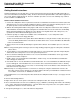
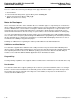
Application Note February 1999 USS-720 USB Port Monitor Description A port monitor is responsible for the communication between the Windows* spooler and a printing device. It controls the I/O port to which the physical printer is connected and is responsible for the communication channel between the spooler and the print device. Typically, the port monitor communicates with base I/O drivers (e.g.
USS-720 USB Port Monitor Application Note February Description (continued) APPLICATION GDI GDI32 PRINTER DRIVER SPOOLER PROCESS ROUTER LOCAL PRINT PROVIDER LANGUAGE MONITOR USB PORT MONITOR USS-720 DRIVER INTERFACE USS-720 DRIVER USB DRIVER INTERFACE USBHUB.SYS USBD.SYS USB DRIVER STACK UHCD.SYS OPENHCI.SYS PCI ENUMERATOR USB BUS HARDWARE INTERFACE USS-720 IN APPLICATION Software provided with the USS-720 5-6004.r6 Figure 1. Printer Cable with Instant USB ™ 13 8-2 Lucent Technologies Inc.
Application Note June 1999 Instructions for Downloading Software for Use with the In-System Design USB Smart Cable Introduction Software Installation Instructions Before you begin, please note: In order to use the software for the In-System Design USB Smart Cable, the PC where the software will be installed must be running either: 1. Point your web browser to http://www.in-system.com to access the In-System Design web site. ■ Windows* 95/version 4.00.
For additional information, contact your Microelectronics Group Account Manager or the following: INTERNET: http://www.lucent.com/micro E-MAIL: docmaster@micro.lucent.com N. AMERICA: Microelectronics Group, Lucent Technologies Inc., 555 Union Boulevard, Room 30L-15P-BA, Allentown, PA 18103 1-800-372-2447, FAX 610-712-4106 (In CANADA: 1-800-553-2448, FAX 610-712-4106) ASIA PACIFIC: Microelectronics Group, Lucent Technologies Singapore Pte. Ltd.