ADVANCED ADJUSTABLE BASE info@lucidmattress.com 888-975-8243 SERIAL NO.
OWNER’S MANUAL ADVANCED ADJUSTABLE BASE
ADVANCED ADJUSTABLE BASE CONTENTS Safety & Warranty Warnings 04 Overview & Parts List 06 Assembly 08 Remote Control & Pairing 12 Synchronizing Two Bases 15 Emergency Power Down 16 Troubleshooting 17 Warranty 18
Safety & Warranty Warnings IMPORTANT: PLEASE READ ALL INFORMATION CAREFULLY BEFORE USING THIS PRODUCT. SAVE THESE INSTRUCTIONS. WARRANTY WARNINGS SAFE OPERATION Do not open or tamper with control box, motors, or remote (with the exception of battery compartments). The warranty will be void if the internal workings of these components are tampered with. • SAFETY WARNINGS • Do not use bed outdoors.
WEIGHT LIMITS FCC COMPLIANCE • This product is not rated to support weights in excess of: • 750 lbs. (340 kgs) - Queen and Full 500 lbs. (226 kgs) - Twin XL • This device complies with Part 15 of the FCC Rules. Operation is subject to the following two conditions: (1) This device may not cause harmful interference, and (2) this device must accept any interference received, including interference that may cause undesired operation.
Overview & Parts List GET TO KNOW YOUR ADJUSTABLE BASE Before beginning assembly of your adjustable base, please take components, as explained here. If any parts or components are missing, or are different than shown in the adjacent image, do not attempt to complete the assembly process and contact customer support by calling 888-975-8243 or emailing info@lucidmattress.com.
REMOTE MATTRESS RETAINER BAR POWER SUPPLY BOX & POWER CORD LEGS CENTER CONNECTION BRACKETS (2) SECURITY STRAP Twin XL Only SYNC CABLE Twin XL Only ADVANCED ADJUSTABLE BASE 07
Assembly NOTES 1. 2. Two people are required to assemble this adjustable base. position, bottom facing up, to avoid damage. STEP 1 Remove folded bed base from the box and carefully unfold the base. Set it mattress i any underside wires along the hinge. STEP 2 Place the center connection brackets over the pre-drilled leg holes located in the middle of the base.
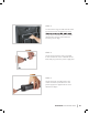
STEP 3 To install the six legs, thread the bolt of the leg into the frame and tighten by hand. on top of the center connection brackets attached from step 2. Then fasten the remaining corner legs. STEP 4 Uncoil the input power cord (connected to the control box on the underside of the base) and plug it into the power supply box. STEP 5 Uncoil the power cord (that has a wall outlet connection) and attach it to the power supply box opposite of the cord attached in Step 4.
Assembly, continued STEP 6 With two to four people, lift the bed by the metal frame and turn it over so the mattress side is facing up. Take caution not to lift the bed with the fabric, or to use the legs as pivot points. This pressure may cause damage. Avoid dragging the base across STEP 7 Ensure two AAA batteries (included) are installed correctly in the remote. STEP 8 Slide the mattress retaining bar into the anchors located at the foot of the bed.
STEP 9 Plug the power cord into the wall outlet and refer to pages 12-15 to set programmable positions, pair the remote, and test functionality. OPTIONAL: If using two separate Twin XL or Split Cal King adjustable bases, wrap a security strap around the front and back legs. This will help prevent movement and maintain stability.
Remote Control OVERVIEW All of the functions of the bed, explained here, can be operated with the remote control. This remote requires two AAA batteries (included) inserted in the back panel. PRESET BUTTONS Zero Gravity (ZG): Elevate the legs slightly higher than the chest, allowing CHILD LOCK Press and hold this button until unlock the remote control keys. reduce stress and fatigue. Anti-Snore (SLEEP): Raise the head to allow for easier air intake.
FLASHLIGHT CHILD LOCK MEMORY POSITION ZERO-GRAVITY MODE PAIR (see page 14) FLASHLIGHT TV MODE HEAD UP FOOT UP FLAT POSITION FOOT DOWN HEAD DOWN ANTI-SNORE MODE HEAD MASSAGE READ MODE FOOT MASSAGE MASSAGE TIMER ALL MASSAGE ON/OFF MASSAGE MODE UNDERBED LIGHTS ADVANCED ADJUSTABLE BASE 13
Remote Control Pairing OVERVIEW The original remote that comes in the box is already paired to the base. No further action is required. In the event that the remote is not paired with the base (as in the case of a replacement remote), begin by checking the following: STEP 1 Ensure the remote batteries are functioning. Replace if necessary. STEP 2 On the control box (underside of base), press the PAIR button twice. The LED light on the control box turns blue.
Synchronizing Two Bases (Twin XL Only) TO PAIR ONE REMOTE TO TWO BASES: STEP 1 next to each other in desired location. Ensure cable into the SYNC input (shown to the left) on each base's control box. STEP 2 With the sync cable installed, use remote and test all functions of the bed base. If remotes are not working, troubleshoot the problem by following the instructions on page 17. The two bases are now connected and ready for normal use.
Emergency Power Down OVERVIEW Your adjustable base supports the emergency power down feature for when a power failure occurs while the head and/or foot sections are raised. INSTALLING BATTERIES Batteries act as a backup power source in case of an outage, but are not necessary to operate the base. Locate and remove the cover on the 9V battery compartment in the power supply unit. Install two alkaline 9V batteries (not included) and replace the cover.
Troubleshooting PROBLEM POSSIBLE SOLUTION No features of the base will activate. Ensure the remote is paired correctly with the base (see page 14). Unplug the power cord, wait 30 seconds and plug back in to reset electric components. The surge protection or the electrical outlet may be defective. Test the outlet by plugging in another working appliance. Head or foot section will elevate, but will Bed mechanism may be obstructed. Elevate bed and check for obstruction. Remove obstruction.
Warranty Information 10-YEAR LIMITED WARRANTY WHAT IS COVERED This warranty covers any defects in materials or workmanship under the conditions and exceptions stated below. bear all labor and shipping costs associated with repair or replacement of the defective part(s). An exception to this is the metal frame, which is covered in full for the duration of the 10-year warranty.
Notes To assist with warranty claims, please keep your receipt and record the following: DATE OF PURCHASE PLACE OF PURCHASE LOT # (found on ID Tag) PO # (found on shipping box label) SERIAL # (found on back cover of this manual) ADDITIONAL NOTES ADVANCED ADJUSTABLE BASE 19