Dual Mass Flywheel Technology / Failure Diagnosis Special Tool / User Instructions
1 History 1 History From conventional torsion damping to dual mass flywheel The rapid development of vehicle technology over the last few decades has brought ever higher-performance engines paralleled by an increased demand for driver comfort. Weight-saving vehicle concepts and wind tunneloptimised bodies now allow other sources of noise to be perceptible to the driver. In addition, lean concepts, extremely low-speed engines and new generation gearboxes using light oils contribute to this.
The configuration of the springs in the first-generation DMF was identical to conventional torsion dampers, where the pressure springs are mounted in a radial direction close to the centre and can therefore provide only limited spring capacity. This design was sufficient to isolate vibration in 6-cylinder engines, as these produce low resonance speeds. In contrast, 4-cylinder engines induce higher irregularities and consequently higher resonance speeds.
1 History DMF – Milestones in technology 1985 Today n Primary mass n Spring/damper system n Secondary mass Vehicles fitted with DMF – figures from 1990 to today 120 Global 105 million Annual figure in millions 100 EU 85 million.
2 Dual mass flywheel – DMF 2 Dual mass flywheel – DMF 2.1 Why DMF? The periodic combustion cycles of a 4-stroke engine create torque fluctuations which causes torsional vibration to be passed down the drive train. The resulting noise and vibration, such as gear rattle, body boom and load change vibration, results in a decrease in both cabin and driving comfort.
2 Dual mass flywheel – DMF 2.3 Function The functioning principle of a DMF is simple, yet efficient. Owing to the additional mass on the transmission input shaft, the vibration torque range, which is normally between 1,200 rpm and 2,400 rpm with original torsion dampers, is moved to a lower resonance speed range. This ensures excellent damping of engine vibration even at idle speeds.
3 DMF components 3 DMF components 3.1 Primary mass The primary mass is connected to the crankshaft of the engine. The inertia of the primary mass and the crankshaft combines to form a whole. Compared to a conventional flywheel, the primary mass of the DMF is significantly more flexible, which helps to relieve the 1 2 3 1 Primary cover 2 Arc spring stop 3 Primary mass For engine starting, the starter ring gear is positioned on the primary mass.
3 DMF components 3.2 Secondary mass The engine torque is transferred from the primary mass to the secondary mass via the arc springs and the flange. Thanks to the bearing between the primary and secondary mass, independent radial movement of the masses is possible. As with a rigid (single-mass) flywheel, the power output is through the clutch, which is bolted to the secondary mass. The crucial difference, however, is that the engine torque is now largely free of rotational vibration, i.e. it is modulated.
3.3 Bearing The bearing in the primary mass serves as a rotating connection with the secondary mass. It not only has to absorb the weight-related radial forces of the secondary flywheel and the clutch, but also the axial forces generated by the release force when disengaging.
3 DMF components 3.3 Bearing Large and small ball bearing The primary mass is fitted with a turned hub on which the large-size ball bearing is fitted. 1 2 3 4 1 Primary mass with bearing seat on hub 2 Hub 3 Large-size ball bearing 4 Cross section – primary mass with hub and large-size ball bearing A hub flange with the bearing seat (turned or drawn) is mounted onto the primary mass. The bearing seat can be adjusted to mount a small ball bearing – as shown here – or a plain bearing.
3.4 Flange The task of the flange is to transfer torque from the primary mass via the arc springs to the secondary flywheel; in other words, from the engine to the clutch. The flange is tightly riveted to the secondary mass with its wings (arrows) sitting between the arc spring channel of the primary mass. The gap between the arc spring stops in the arc spring channel is big enough to enable the flange to rotate.
3 DMF components 3.4 Flange At high engine speeds, the resulting centrifugal forces press the arc springs to the outside against the guides and the coils are disabled. Consequently, the arc spring stiffens and spring action is partly lost. In order to maintain sufficient spring action, straight pressure springs are mounted in the flange. Owing to their lower mass and mounting position on a smaller radius, these springs are subject to a lower centrifugal force.
3.5 Friction control disc During the start-up process, the DMF operates briefly in the resonant frequency range. When this happens, the flange wings repeatedly hit the arc springs with unbraked force, producing noise as they do so. An effective countermeasure here is an additional friction device, the friction control plate. This has the effect of delaying the rotation of the flange within a defined working range.
3 DMF components 3.6 Arc springs Single spring The basic version of the arc spring is a single spring. This is characterised by its large spring volume and resulting high damping capacity. Because of its simple design, however, it only offers limited possibilities for satisfying rising demands for comfort. For this reason, today’s DMFs are seldom fitted with single springs. Single-step parallel spring The arc springs in most frequent use today are singlestage parallel springs.
4 Special forms of the DMF 4 Special forms of the DMF Damper for the double clutch transmission (DCT) The flywheel used in the DCT is a special form of the LuK DMF. As in the conventional DMF in manual gearboxes, there is a primary and a secondary side. However the secondary side, in contrast to the conventional DMF, is not a fixed part of the DMF, so it is not designed as a flywheel mass but in the form of a flange. It serves only as a connection between the primary mass and the double clutch.
4 Special forms of the DMF 4 Special forms of the DMF Driveplate DMF Since 2008, a new gearbox generation has been fitted in some Audi models. These gearboxes can be recognised by the different arrangement of the differential. This is now in front of the clutch in the direction of travel. As a result, the power flow to the left drive shaft has to be transmitted straight through the bell housing by a flanged shaft. Because of this, use of a conventional DMF is no longer possible.
Centrifugal pendulum-type absorber DMF The DMF with centrifugal pendulum-type absorber has been developed to further increase damping capacity at low engine speeds. Using no additional installation space, a further additional mass (the centrifugal pendulumtype absorber) has been added to the two main masses in the DMF. It consists of three or four double pendulum masses which sit on the DMF flange. They are suspended on two studs which move in kidney-shaped paths in the pendulum masses and in the flange.
4 Special forms of the DMF 4 Special forms of the DMF Damped Flywheel Clutch (DFC) When replacing the clutch and DMF, the DFC is a proven repair alternative. It consists of a pre-assembled, tuned assembly unit of DMF, clutch disc and clutch pressure plate. The preassembly of the individual components in the factory saves considerable time in the workshop, as the DFC can be mounted directly on the engine. No clutch assembly work is necessary.
DMF for Continuously Variable Transmission (CVT) In a fully automatic gearbox, the torque converter acts, among other things, as a centrifugal oscillation damper in the drive train. CVT gearboxes, however, work without a torque converter. Therefore, the centrifugal damping is provided by a special form of the DMF. The crucial difference from the DMF designs described above is in the design of the torque output.
5 DMF failure diagnoses 5 DMF failure diagnosis 5.1 General advice on inspecting the DMF Always check the DMF when replacing the clutch. A worn and defective DMF can damage the newly installed clutch. In the event of a customer complaint, targeted questions help to identify the fault.
5.2 Noise Special references The following is permissible on some vehicle makes and models and has no effect on the operation of the clutch components: • Small trails of grease on the DMF rear face (engine side) leading from the holes towards the flywheel edge. • The secondary mass can be rotated by several centimetres against the primary mass and does not automatically return to its original position. On a DMF with a friction control disc a hard knock can be felt and heard.
5 DMF failure diagnoses 5.2 Noise Summary of general inspections in the case of noise The following summary points out possible fault sources which may be erroneously attributed to a defective DMF. Only after an exhaustive inspection should a decision be made to replace the DMF. LuK Service Info provides additional information for a reliable diagnosis.
5.3 Chip tuning Chip tuning is a quick, easy and fairly inexpensive way of increasing engine power output. For a relatively small amount of money you can easily increase the power of an engine by up to 30%. Facts not normally considered are whether the engine is durable enough to withstand the higher outputs, e.g. thermal overloading, and also if the rest of the drive train can withstand the increase in torque/performance.
5 DMF failure diagnoses 5.4 Visual inspection/damage patterns 1. Clutch driven plate Description • Clutch disc burnt Cause • Thermal overload of the clutch driven plate occurring, e.g. when the wear limits were exceeded Effect • Thermal load applied on the DMF Remedy • Perform a visual inspection for signs of thermal discolouration on the DMF For damage assessment refer to: • Low/mean/high thermal load (page 24) • Very high thermal load (page 25) 2.
4. Friction surface Description • Scoring Cause • Worn-out clutch g Clutch lining rivets score on friction surface Effect • Limited power transmission capability • The clutch is unable to generate the required torque • Damage to the DMF friction surface Remedy • Replace DMF 5. Friction surface Description • Localised, dark hot spots g Sometimes many spots Effect • DMF subjected to high thermal load Remedy • No remedial measures required 6.
5 DMF failure diagnoses 5.4 Visual inspection/damage patterns 7. Ball bearing Description • Grease leakage • Bearing seized • Sealing cap missing or discoloured (brown) due to overload Cause • Thermal overload or mechanical damage/overload Effect • Degradation of bearing lubrication g DMF fails Remedy • Replace DMF 8. Plain bearing Description • Damaged or destroyed Cause • Wear and/or mechanical impact Effect • DMF is defective Remedy • Replace DMF 9.
10. Low thermal load Description • Friction surface slightly discoloured (gold/yellow) g No tarnish at the outer edges of the DMF or in the rivet area Cause • Thermal load Effect • None Remedy • No remedial measures required 11.
5 DMF failure diagnoses 5.4 Visual inspection/damage patterns 13. Very high thermal load Description • DMF discoloured blue/purple at the side or on the back and/or is visibly damaged, e.g. cracks Cause • Very high thermal load Effect • DMF is defective Remedy • Replace DMF 14. Friction control disc Description • Friction control disc melted Cause • High thermal load inside the DMF Effect • Limited operational reliability of the DMF Remedy • Replace DMF 15.
16. Starter ring gear Description • Starter ring gear heavily worn Cause • Defective starter Effect • Noise occurring during engine start Remedy • Replace DMF • Perform starter function test 17.
5 DMF failure diagnoses 5.4 Visual inspection/damage patterns 18. Minor grease egress Description g Slight trails of grease leaking from the openings or seal caps Cause • Because of the design, small amounts of grease seepage is permissible Effect • None Remedy • No remedial measures required 19. Heavy grease leakage Description • Grease egress greater than 20 g g Housing covered with grease Effect • Lack of lubrication of the arc springs Remedy • Replace DMF 20.
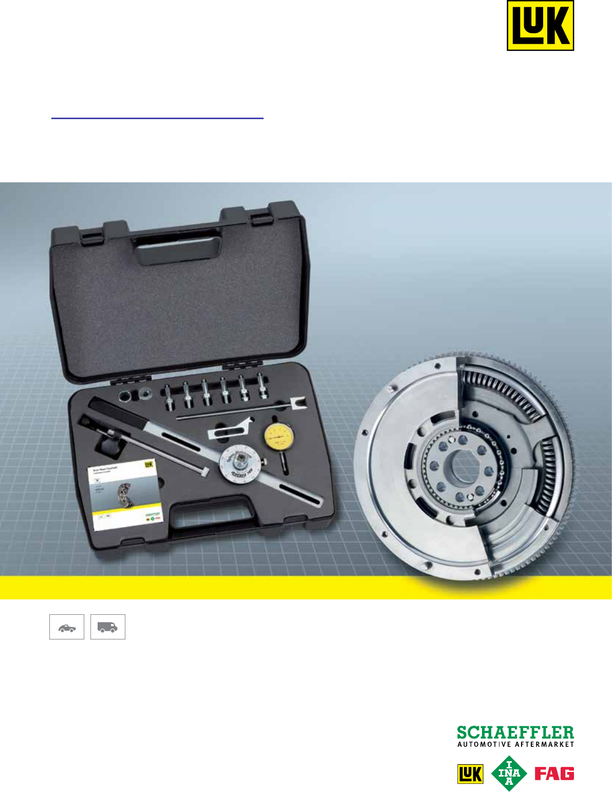
6 Description and shipment of the DMF special tool 6 Description and shipment of the DMF special tool a workshop environment. The freeplay angle is the angle at which the DMF’s primary and secondary masses can be rotated against each other until load is exerted on the arc springs. Tilting clearance occurs when the rotating masses of the DMF are tilted towards or away from one another. Item no.
6 Description and shipment of the DMF special tool 3 4 2 1 5 8 6 7 Item no.
7 DMF function tests 7 DMF function tests The LuK special tool allows you to perform the following tests on the DMF: • Measuring the freeplay angle • Measuring the rock These tests, in combination with a visual inspection to check grease egress, thermal load, clutch condition, etc., allow for a reliable assessment of the DMF’s operational condition. The freeplay angle is the angle at which primary and secondary mass can be rotated against each other until load is exerted on the arc springs.
7 DMF function tests 7.1 Which test suits which DMF? On DMFs with an even number of threaded holes to secure the clutch pressure plate, the slotted bar can be mounted centrally, making it possible to determine the freeplay angle using a degree gauge. As this measuring method can be used on almost all DMF types, it should be the preferred method – see Chapter 7.2.
7.2 Freeplay measurement with degree gauge 1. Remove the gearbox and clutch according to the manufacturer’s instructions. 2. Screw the appropriate adapters (M6, M7 or M8) into two vertically opposing clutch bolt holes on the DMF and torque down. 3. Centralise the slotted bar on the adapters by using the graduations and tighten the nuts. The degree gauge must be positioned centrally on the DMF. 4.
7 DMF function tests 7.2 Freeplay measurement with degree gauge If the locking tool can only be mounted to a hole with a dowel fitted, use the adaptor sleeve provided over the dowel. 5. Bolt the dial gauge stand to the engine block using a suitable bolt, i.e. a gearbox bolt and, if required, the adaptor sleeve can be used in a similar way to the locking tool. The same bolt can be used to fasten the locking dogs and the dial gauge stand if required.
6. Fit the degree gauge locking bar to the degree gauge and the dial gauge stand and tighten the knurled screw. 7. Use the slotted arm to rotate the secondary mass anticlockwise until the arc spring force can be felt. Caution: Some DMFs have a friction control disc that can be felt as a hard stop in one direction. In this case apply greater force to rotate the secondary mass a few more millimetres until spring resistance can be felt, and then allow it to return.
7 DMF function tests 7.2 Freeplay measurement with degree gauge 9. Use the slotted arm to rotate the secondary mass clockwise until the arc spring force can be felt. 10. Slowly release the slotted arm, allowing the arc springs to relax. Read off the degree gauge and compare the measurement against the rated value – see rated value table in Chapter 8.
7.3 Freeplay measurement by counting starter ring gear teeth 1. Remove the gearbox and clutch according to the manufacturer’s instructions. 2. Screw the appropriate adapters (M6, M7 or M8) into two approximately vertically opposing clutch bolt holes on the DMF and torque down. 3. Centralise the slotted bar on the adapters by using the graduations and tighten the nuts. As there is an odd number of clutch bolt holes, the slotted arm cannot be fixed centrally on the DMF. 4.
7 DMF function tests 7.3 Freeplay measurement by counting starter ring gear teeth If the locking tool can only be mounted to a hole with a dowel fitted, use the adapter sleeve provided over the dowel. 5. Use the slotted arm to rotate the secondary mass anticlockwise until the arc spring force can be felt. Caution: Some DMFs have a friction control disc that can be felt as a hard stop in one direction.
7. Rotate the secondary mass clockwise until the arc spring force can be felt. Slowly release the slotted arm, allowing the arc springs to relax. 8. Count the number of teeth of the starter ring gear between the original mark and its current position and compare against the rated value – see rated value table in Chapter 8.
7 DMF function tests 7.4 Rock measurement 1. Fit the dial gauge and arm to the dial gauge stand. 2. Centralise the dial gauge on the adapter and set to the required preload. Caution: The measurement should be done gently. Applying too much force will result in inaccurate measurements and could damage the DMF. 3. Gently push the slotted arm towards the engine (using your thumb, for example) until resistance can be felt. Keep the slotted arm in this position while setting the dial gauge to “0”.
4. Pull the lever gently in the opposite direction (using your finger, for example) until resistance can be felt. Read off the dial gauge and compare the measurement against the relevant rated value – see rated value table in Chapter 8.
8 Bolts for DMFs and DFCs 8 Bolts for DMFs and DFCs Why are not all DMFs supplied with the necessary bolts? The required bolts are already supplied with some of the approx. 350 different articles that make up the delivery range. However, for many DMFs, different bolts are required depending on the vehicle model. For this reason, all DMFs have their own reference/ order code, which indicates whether or not the bolts are included in the delivery.