LUKAS D Betrie bsanleitung Betriebsanleitung Man uel d'utilisa tion Manuel d'utilisation GB E uctions Instructions Opera Oper ating Instr © BELL SRL - COD. 193555075 - v.
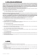
155 36 162 129 109 147 320 Fig.1 236 6 Ø6 66 90 6 R= 3 Fig.2 Fig.3 2 Fig.4 COD. 193555075 - v.
Fig.5 Fig.6 Fig.7 E Fig.8 COD. 193555075 - v.2 - UPD 220207 Fig.
INHAL T INHALT ALLGEMEINE HINWEISE ......................................................................................................................................................................................... 6 1 TRANSPORT, LAGERUNG UND AUSPACKEN DER PUMPE ................................................................................................................................ 6 2 BESCHREIBUNG ..............................................................................................
SOMMAIRE GENERALITES ........................................................................................................................................................................................................ 20 1 TRANSPORT, STOCKAGE ET DÉBALLAGE DE LA POMPE ............................................................................................................................... 20 2 DESCRIPTION ............................................................................................
ALL GEMEINE HINWEISE ALLGEMEINE Vor Installation und Benutzung dieser Pumpe muß das vorliegende Handbuch aufmerksam durchgelesen werden, da es wichtige Hinweise für Ihre Sicherheit enthält. Dieses Handbuch muß immer bei der Pumpe und der Maschine, an der sie installiert wird, bleiben, auch wenn sie verkauft bzw. veräußert wird.
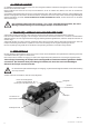
3 - SICHERHEIT Alle nachstehend beschriebenen Vorschriften sind strikt zu befolgen, denn sie sind von größter Bedeutung für Ihre eigene Sicherheit und für die Sicherheit anderer Personen. Neben den Angaben dieses Kapitels sind außerdem auch alle sonstigen in diesem Handbuch enthaltenen Anweisungen zu befolgen. VERSUCHEN SIE UNTER KEINEN UMSTÄNDEN, DIE INSTALLIERTEN SCHUTZVORRICHTUNGEN ABZUNEHMEN ODER ZU VERÄNDERN.
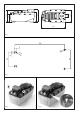
4 - TECHNISCHE MERKMALE Typ Teile-Nr. Druck am Lufteinlass (bar) Luftanschluss Max. Betriebsdruck*, ölseitig (MPa) Förderleistung (l/min.) Ölmenge in liegender Stellung (l) / nutzbare Menge (l) Ölmenge in stehender Stellung (l) / nutzbare Menge (l) Hydr. Anschluss,Druck Hydr. Anschluss, Rücklauf Geräuschpegel Abmessungen ** (L x B x H) Gewicht mit Öl (Kg) AHP21E-632 HR149 463 260 2,8 ÷ 10 G ¼ Innengewinde 63 ±1 s.
5 - INST ALL ATION UND INBETRIEBN AHME INSTALL ALLA INBETRIEBNAHME In diesem Kapitel wird die Installation der Pumpe beschrieben. Die folgenden Anleitungen werden als die optimale Vorgangsweise empfohlen.
6.2 - Betrieb der Steuerungen Die Pumpe ist für die Verbindung mit einem 3/2 oder 4/2 Wegesitzventil mit Anschluß CETOP 03 ausgelegt. Für einen korrekten Anschluß des Ventils CETOP an der Pumpe verweisen wir auf die dem Ventil beiliegende technische Dokumentation. ACHTUNG: nach der erstmaligen Installation der Pumpe kann es unter Umständen vorkommen, daß der Kreislauf wegen vorhandener Luftblasen leer erscheint.
7.5 - Betriebsstörungen und Abhilfen Im folgenden Abschnitt sind einige Anomalien aufgeführt, die während des Betriebs auftreten können, daneben sind die entsprechende Abhilfen beschrieben. Falls die Probleme nicht mit den hier beschriebenen Eingriffen behoben werden können, muß der Hersteller zu Rate gezogen werden. Betriebsstörung Mögliche Ursache Die Pumpe startet nicht. Die Druckluftzuleitung ist geschlossen oder Sicherstellen, daß Druckluft zur Pumpe verstopft. gelangt.
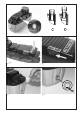
BETRIEBSSCHEMA a b A S A = Lufteintritt a und b = Ölverwendung S = Öltank GARANTIE Garantie auf Material- und Fabrikationsfehler der Pumpen wird entsprechend den allgemeinen Lieferbedingungen geleistet. Einschränkungen: 1) Bevor er an der Maschine Reparatureingriffe in Garantie vornimmt, muß der Vertragshändler vom Hersteller hierzu befugt werden. 2) Die Garantie ist auf die vom Hersteller als defekt anerkannten Teile beschränkt. 3) Für Eingriffe in Garantie werden keine Transportkosten anerkannt.
GENERAL PRECA UTIONS PRECAUTIONS This manual contains important safety information: read carefully before installing and using the pump. This manual must always accompany both the pump and the machine on which the pump is installed, even when pump and machine or the pump alone is sold, loaned or otherwise transferred to other premises.
3 - SAFETY Observe all the following safety rules. They are of the maximum importance for your own safety and the safety of others. In addition to the indications in this chapter, observe also the prescriptions in all other sections of the manual. DO NOT TAMPER WITH THE PROTECTIONS AND SAFETY DEVICES AND DO NOT MODIFY THE PUMP IN ANY WAY TO AVOID CREATING POTENTIALLY HAZARDOUS SITUATIONS FOR WHICH THE OPERATOR OR SERVICE TECHNICIAN IS UNPREPARED.
4 - TECHNICAL SPECIFICA TIONS SPECIFICATIONS Model Part No.. Air inlet pressure (bar) Air connection Maximum working pressure* (MPa) Rated flow (l/min.
5 - INST ALL ATION AND ST AR T-UP INSTALL ALLA STAR ART This chapter describes the methods of installation of the pump. The method here recommended will give excellent results. The purchaser of the pump, i.e. the manufacturer of the machine on which the pump will be installed, may opt for different types of installation, using brackets or any other types of accessory considered to be necessary.
6.2 - Using the controls The pump can be connected to a 3/2 or 4/2 directional control valve with a CETOP 03 connection. For instructions on connecting the CETOP valve correctly, refer to the documentation supplied with the valve itself. WARNING: immediately after the pump installation, the circuit may contain air locks that prevent pressurization. If the pump is unable to pressurize the oil circuit, proceed as described below.
7.5 - Troubleshooting The following chart describes the main problems that could occur during operation of the pump, together with an indication of the appropriate corrective action. If the prescribed action fails to solve the problem, contact the manufacturer.
OPERA TION DIA GRAM OPERATION DIAGRAM a b A S A = Air inlet a and b = Oil use S = Oil reservoir WARRANTY The pump is guaranteed against material and manufacturing defects according to our standard terms and conditions for export valid at the time of placing the order. LIMITATIONS: 1) The dealer must get authorization from the manufacturer before carrying out any repair work on equipment still under warranty. 2) The warranty is limited only to parts acknowledged by the manufacturer as being defective.
GENERALITES Avant dinstaller la pompe et de lutiliser, lire attentivement dun bout à lautre le présent manuel, car il contient des remarques importantes pour votre sécurité. Ce manuel doit toujours rester à proximité de la pompe et de la machine sur laquelle elle est installée, même en cas de vente ou de changement de propriétaire.
3 - SÉCURITÉ Toutes les prescriptions décrites ci-après doivent être strictement observées, car elles sont de la plus grande importance pour votre propre sécurité et pour la sécurité dautres personnes. Outres les indications figurant dans le présent chapitre, il faut aussi observer toutes les autres directives se trouvant dans ce manuel. Nessayez en aucun cas denlever ou de modifier les dispositifs de protection installés.
4 - CARA CTÉRISTIQUES TECHNIQUES CARACTÉRISTIQUES Modèle Part Nr. Pression à lentrée dair (bars) Raccordement dair Pression maximale de fonctionnement* (MPa) Capacité nominale (l/min.
5 - INST ALL ATION ET MISE EN SER VICE INSTALL ALLA SERVICE Dans ce chapitre est décrite linstallation de la pompe. Les directives suivantes sont recommandées comme la façon optimale de procéder.
6.2 - Fonctionnement des commandes La pompe est conçue pour être reliée à un distributeur à sièges à 3/2 ou 4/2 voies avec raccordement CETOP 03 Pour un raccordement correct de la vanne CETOP sur la pompe, nous renvoyons à la documentation technique jointe à la vanne. ATTENTION : Après la première installation de la pompe, il peut arriver éventuellement que le circuit paraisse vide du fait de la présence de bulles dair.
7.5 - Dérangements et remèdes Dans le chapitre suivant sont exposées quelques anomalies qui peuvent apparaître pendant le fonctionnement; en face sont décrits les remèdes correspondants. Si les problèmes ne peuvent pas être résolus au moyen des interventions décrites ici, il faut consulter le fabricant. Dérangement Cause possible Remède La pompe ne démarre pas. La tuyauterie dalimentation en air comprimé est fermée ou engorgée. Assurer que lair comprimé arrive à la pompe.
SCHEMA DE FONCTIONNEMENT a b A S A = Entrée dair a et b = Utilisation dhuile S = Réservoir à huile GARANTIE Pour des vices de matériau ou de fabrication de la pompe, il est donné une garantie de 12 (douze) mois à partir de la date de livraison. RESTRICTIONS: 1) Avant de procéder à des travaux de réparation sur la machine sous garantie, le concessionnaire doit y être habilité par le fabricant. 2) La garantie se limite aux pièces reconnues par le fabricant comme défectueuses.
AD VER TENCIAS GENERALES ADVER VERTENCIAS Antes de la instalación y el uso de esta bomba lean atentamente todo lo detallado en el presente manual, ya que el mismo contiene advertencias importantes para su seguridad. Este manual deberá acompañar siempre a la bomba y a la máquina en la que se halle instalada, incluso en caso de venta o cesión de la misma.
3 - SEGURID AD SEGURIDAD Sigan atentamente todas las reglas descritas a continuación, ya que son muy importantes para su seguridad y la de las demás personas. Además de las indicaciones detalladas en este capítulo, deberán tener en cuenta todas las demás señaladas en el manual. NO INTENTEN ALTERAR LAS PROTECCIONES INSTALADAS, NI MODIFIQUEN NINGÚN COMPONENTE DE LA BOMBA, YA QUE PODRÍAN CREARSE SITUACIONES DE PELIGRO PARA LAS QUE NI EL OPERADOR NI EL ENCARGADO DEL MANTENIMIENTO ESTÁN PREPARADOS.
4- CARA CTERÍSTICAS TÉCNICAS CARACTERÍSTICAS Modelo Part No.. Presión entrada aire (bares) Unión aire Presión máxima de utilización* (MPa) Caudal nominal (l/min.) Contenido aceite en pos. horizontal /cantidad utilizable (I) Contenido aceite en pos.
5 INST AL ACIÓN Y PUEST A EN FUNCIÓN INSTAL ALA PUESTA En este capítulo se describen las modalidades de instalación de la bomba. Dichas indicaciones son aconsejadas como óptimas.
6.2 - Uso de los mandos La bomba está preparada para la conexión a una válvula direccional 3/2 ó 4/2 con unión CETOP 03. Para efectuar una unión correcta de la válvula CETOP a la bomba, consulten la documentación que acompaña a la válvula. ATENCIÓN: puede que, tras la primera instalación de la bomba, el circuito esté descargado por la presencia de burbujas de aire. En caso de que la bomba no logre poner bajo presión el aceite, efectúen lo descrito seguidamente.
7.5 Problemas y soluciones En el apartado siguiente se indican algunas anomalías que pueden advertirse durante el funcionamiento de la bomba y su solución. Si, actuando del modo descrito, no pudiera resolverse dicha situación crítica, consulten al fabricante. PROBLEMA POSIBLE CAUSA SOLUCIÓN La bomba no se pone en marcha La línea del aire comprimido está cerrada u obstruida. Verificar que llegue aire comprimido a la bomba. La bomba se bloquea bajo carga Presión del aire demasiado baja.
ESQUEMA DE FUNCION AMIENT O FUNCIONAMIENT AMIENTO a b A S A = Entrada aire a y b = Uso del aceite S = Depósito del aceite GARANTÍA La bomba posee una garantía que cubre defectos de material y fabricación durante un periodo de 12 (doce) meses, contados a partir de la fecha de entrega. LIMITACIONES: 1) El concesionario deberá ser autorizado por el fabricante antes de actuar s o b r e la máquina para efectuar reparaciones en garantía.
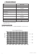
TAB.1 34 COD. 193555075 - v.
ERSA TZTEILLISTE - LIST OF SP ARE P AR TS ERSATZTEILLISTE SPARE PAR ARTS (T AB (TAB AB.. 1) POS.
LISTE DES PIECES DE RECHANGE - REPUEST OS REPUESTOS (T AB (TAB AB.. 1) POS.
COD. 193555075 - v.2 - UPD 220207 37 51 50 52 56 52 53 54 59 57 11 55 60 TAB.2 TOOL 55 54 6-6.
ERSA TZTEILLISTE - LIST OF SP ARE P AR TS ERSATZTEILLISTE SPARE PAR ARTS (T AB (TAB AB.. 2) POS.
LISTE DES PIECES DE RECHANGE - REPUEST OS REPUESTOS (T AB (TAB AB.. 2) POS.
© BELL SRL - COD. 193555075 - v.