
User Manual
16
COD. 193555075 - v.2 - UPD 220207
5 - INST5 - INST
5 - INST5 - INST
5 - INST
ALLALL
ALLALL
ALL
AA
AA
A
TION AND STTION AND ST
TION AND STTION AND ST
TION AND ST
ARAR
ARAR
AR
TT
TT
T
-UP-UP
-UP-UP
-UP
This chapter describes the methods of installation of the pump. The method here recommended will give excellent results. The
purchaser of the pump, i.e. the manufacturer of the machine on which the pump will be installed, may opt for different types of
installation, using brackets or any other types of accessory considered to be necessary. HOWEVER, THE ORIGINAL SHAPE AND
ATTACHMENT OF THE PUMP MUST NOT BE MODIFIED, THE PROTECTIONS APPLIED TO THE PUMP MUST NOT BE TAMPERED
WITH AND NO ACTION MUST BE TAKEN THAT COULD MAKE THE PUMP POTENTIALLY DANGEROUS. If these instructions are
disregarded, the person who is responsible for the modifications automatically assumes full liability for any accidents that may occur
during use of the pump.
The pump can be installed in a horizontal or vertical position.
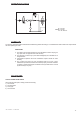
Figure 3 on page 2 shows the drilling template to use when designing the pump baseplate. The pump must be anchored to the
baseplate using four screws.
IMPORTANT: the fixing hole depth is 20 mm. This length must not be exceeded.
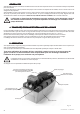
5.1 Filling the reservoir (if the pump is supplied without oil)
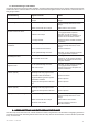
Page 15 shows the oil quantities required to fill the pump reservoir. The table also shows the actual usable oil capacities.
Use the oil types specified on page 15. The use of oil with different characteristics can result in serious damage to the pump and render
it unsuitable for use. THE MANUFACTURER SHALL NOT BE HELD RESPONSIBLE FOR INJURY TO PERSONS OR DAMAGE TO
PROPERTY CAUSED BY THE USE OF UNSUITABLE OR EXHAUST OIL. DAMAGE TO THE PUMP RESULTING FROM THE
ABOVE MENTIONED CAUSES IS NOT COVERED BY THE WARRANTY.
l Use a slotted tip screwdriver to remove the filler plug (fig.10, page 13)
l Pour the correct quantity of oil into the reservoir (refer to the table on page 15)
l Clean the edges of the filler opening with a clean cloth and refit the plug, pressing it down fully.
5.2 - Pump hydraulic connections
l Connect the hydraulic pressure hoses to the outlet port (A, fig. 3, page 2) and reservoir port (B, fig. 3) on the pump. The hoses must
be fitted with a M14x1.5 coupling.
5.3 - Setting up the pump
5.3.1 - Setting up the pump - horizontal position
l If the pump is to be used in the horizontal position, unscrew the breather screw (fig.4, page 2) by three or four turns using the correct
type of screwdriver.
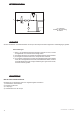
5.3.2 - Setting up the pump - vertical position
l If the pump is to be used in the vertical position, use a slotted tip screwdriver to extract the breather plug to the first click (pos. D in
fig. 5, page 3).
5.4 - Connecting the compressed air line
l Select a quick coupler that is suitable for your air line, bind the thread with Teflon tape, and then screw it into the compressed air
inlet connection (fig.10, page 13).
l The quick coupler must be connected to an air line supplying compressed air at between 2.8 and 10 bar (see Specifications, page 15).
6 - OPERA6 - OPERA
6 - OPERA6 - OPERA
6 - OPERA
TIONTION
TIONTION
TION
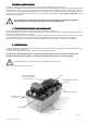
6.1 - Using the treadle
The pump in your possession can be used for either continuous or intermittent duty:
l Intermittent duty: press and release the treadle to start and stop the pump (fig.6, page 3).
l Continuous duty: press the treadle (fig.6, page 3) then push in the locking pin (fig.7, page 3) to lock the treadle control in the on
position. The pump will now start working, the operating mode depending on the type of actuator installed.
Press the treadle firmly to release the pin and stop the oil flow.