Operating instructions Rerailing Equipment Control desks (model CT7) 84072134485 GB Edition 08.
Content Page 1. Hazard classes 4 2. Product safety 5 3. Proper use 8 4. Functions and performance 9 4.1 Description 9 4.2 Hydraulic supply 9 4.3 Overview 10 4.4 Hydraulic circuit diagrams for standard control desks 11 4.5 Optional accessories 14 5. Connection of hydraulic devices 14 5.1 Basic information 14 5.2 Connection of quick-connect couplings 15 6. Operation 16 6.1 Setting up the control desk 16 6.2 Start-up 16 6.3 Control desk controls 17 7.
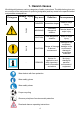
1. Hazard classes We distinguish between various categories of safety instructions. The table below gives you an overview of the assignment of symbols (pictograms) and key words to the specific hazard and possible consequences.
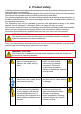
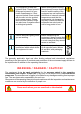
2. Product safety LUKAS products are developed and manufactured in order to guarantee the best performance and quality when used properly. Operator safety is the most important aspect of the product design. Moreover, the operating instructions are intended to ensure LUKAS products are used safely.
In the event of malfunctions, immediately shut down the equipment and secure it. The malfunction is to be repaired immediately. Do not carry out any changes (additions or conversions) to the equipment without obtaining the prior approval of LUKAS. Comply with all the instructions regarding safety and danger on the equipment and in the operating instructions. All the instructions regarding safety and danger on the equipment are to be kept complete and in a legible condition.
The equipment is filled with hydraulic fluid. These hydraulic fluids can be harmful to your health if swallowed or if their vapours inhaled. Direct contact with the skin is to be avoided for the same reason. Please also note that hydraulic fluids can also have a negative effect on biological systems.
3. Proper use LUKAS control desks have been developed specifically for rerailing operations. They are intended to control the hydraulic jacks and pushers used in the event of a railway vehicle derailment. The accessories required for the derailment incident concerned must be used (depending on the variant, e.g. pedestal). CAUTION! To minimise the risk to the environment, remedy leaks as soon as possible. Accessories and spare parts for the control desks are available from your authorised LUKAS dealer.
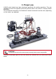
4. Functions and performance 4.1 Description The control desks in the CT7 model series comprise a number of valves housed in a control block. The valves are controlled by means of control levers. Depending on the version, up to 6 double-acting and 2 single-acting hydraulic devices can be connected and controlled without the need for a separate controller. The attached, manually operated pressure shut-off valve opens and closes the supply to the control valves.
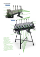
4.3 Overview Operator's 4 5 1 3 9 6 2 Working 5 4 4 7 7 9 1 Switch valves 2 Switch lever 3 Manual pressure shut-off valve 4 Pushbutton valve 5 Pressure gauge 6 Connection for hydraulic supply 7 Connection for singleacting hydraulic devices (e.g.
Return line to hydraulic unit 30 MPa Supply line from hydraulic unit 30 MPa 30 MPa 4.
CT7 - 6/4DV: Return line to hydraulic unit 30 MPa 30 MPa Supply line from hydraulic unit 30 MPa 30 MPa 12
Return line to hydraulic unit 30 MPa Supply line from hydraulic unit 30 MPa 30 MPa 30 MPa CT7 - 6/4DVV: 13
4.5 Optional accessories 4.5.1 Pedestal The pedestal is intended to provide safe support for the control unit and to enable the operator to work standing up. The control unit is fitted to the pedestal as follows: 1. Loosen connection “F” approximately 15 mm (in.) on pedestal “G”. 2. Fit control unit “J”, mounted on leg “H”, onto the pedestal and retighten connection “F” on both sides. 3. Removal in reverse order. J H F G 4.5.
WARNING / DANGER / CAUTION! Before connecting equipment, make sure that all the components used are suitable for the maximum operating pressure of the pump unit. In cases of doubt, you must consult LUKAS directly. 5.2 Connection of quick-connect couplings The device connects to the hydraulic pump by means of individually coded quick-connect coupling halves (plug and socket). X Before coupling, remove the dust protection caps, then pull back and hold the locking sleeve of the female coupling (position X).
6. Operation 6.1 Setting up the control desk Control desks must be set up at a safe distance from the load to be lifted or pushed. Both the load and the implements must be clearly visible from the control desk position. Make sure that the control desk has stable footing. Use suitable material for support if necessary. REMARK: Set up all other necessary components as described in the separate operating instructions for these components.
2. Then start the hydraulic unit. 3. Move the lever on the manual pressure shut-off valve into the working position (turn anti-clockwise to the stop). WARNING / DANGER / CAUTION! In the interests of safety, control desk functions should not remain enabled (manual pressure shut-off valve opened) unless at least one appropriately trained operator is manning the control desk. For emergency use, a single handle is provided to close the pressure shut-off valve.
6.3.2 Controlling double-acting hydraulic devices Double-acting hydraulic devices are controlled by control levers. Throwing the control lever away from the operator's side causes the lower hydraulic connection (usually colour-coded blue) to be supplied with hydraulic fluid. Throwing the control lever towards the operator's side causes the upper hydraulic connection (usually colourcoded red) to be supplied with hydraulic fluid.
8. Maintenance and service A visual inspection must be carried out after each use and at least once a year regardless of use. In addition, a function test must be carried out every 3 years, or whenever there is any doubt as to the safety or reliability of the equipment (observe all applicable national and international rules and regulations relating to the maintenance intervals of the hydraulic devices). CAUTION! Clean off any dirt before checking the equipment.
REMARK: Before you use couplings from a different company, you must contact LUKAS or an authorised dealer. CAUTION! Since LUKAS rerailing devices are designed for top performance, only those components in the spare parts lists of the relevant unit may be replaced. Further components in the devices may only be replaced if: - You have participated in appropriate LUKAS service training, - You have the explicit permission of the LUKAS customer service (on request, check for granting permission.
9.3 Repairs 9.3.1 Coupling replacement The couplings must be replaced in the event of: - external damage - the locking device not working - hydraulic fluid continually leaking in a coupled/uncoupled state. WARNING / DANGER / CAUTION! Never repair couplings: they are to be replaced by original LUKAS parts. During installation, tighten the coupling to a torque of MA = 40 Nm. Procedure: 1. Remove the coupling. 2. Fit the new coupling and screw it in with a torque of MA = 40 Nm. 9.3.
10. Troubleshooting Trouble Connected implements move slowly or jerk in response to control command Check Hose lines connected correctly? Cause Solution Air in the hydraulic Vent the hydraulic system system Pump assembly running? Defective implement. Connected implements do not move in response to control command and no pressure reading on the control desk pressure gauge. Hose lines connected correctly? Hose line to hydraulic unit not connected correctly.
hose assembly cannot be coupled Pressurised Switch the pump to depressurised circulation Coupling defective Coupling needs to be replaced immediately Leak in the couplings Coupling damaged? Coupling defective Coupling needs to be replaced immediately If it is not possible to rectify the malfunctions, inform an authorised LUKAS dealer or the LUKAS Customer Service department immediately.
11. Technical data As all values are subject to tolerances, there may be minor differences between the data achieved by your equipment and the data specified in the following table. 11.1 Control unit Designation CT7-6/3DV Ref. no. Dimensions (L x W x H) [in.] CT7-6/4DVV 840721344 840721345 840721346 801 x 335 x 500 931 x 335 x 500 986 x 335 x 500 35.5 x 13.2 x 19.7 36.7 x 13.2 x 19.7 38.8 x 13.2 x 19.7 Max. operating pressure (HP) [Mpa]* 53 53 53 [psi.] 7,687 7,687 7,687 Max.
11.3 Control desk (control unit + pedestal) CT7-6/3DV CT7-6/4DV CT7-6/4DVV (with pedestal) (with pedestal) (with pedestal) Ref. no. 840721341 840721342 840721343 Comprising: (ref. nos.) 840721344 840721345 840721346 Designation Dimensions (L x W x H) Weight [mm] [in.] 840720325 840720325 840720325 801 x 700 x 1100 931 x 700 x 1100 986 x 700 x 1100 35.5 x 27.6 x 43.3 36.7 x 27.6 x 43.3 38.8 x 27.6 x 43.3 [kg] 44,5 52,0 59,3 [lbs.] 98.1 114.6 130.7 11.
12.
13.
Please dispose all packaging materials and dismantled parts properly. LUKAS Hydraulik GmbH Tel.: (+49) 0 91 31 / 698 - 0 Fax.: (+49) 0 91 31 / 698 - 394 e-mail: lukas.info@idexcorp.com Made in GERMANY CT7_BA_GB_84072134485_0809.