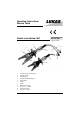
Operating Instructions Rescue Tools 84150/6239-85 GB Issue 09.2005 Combi tools Series LKS replaces 08.
1 Basic operation and designated use of the machine The machine has been built in accordance with state-of-the-art standards and the recognized safety rules. Nevertheless, its use may constitute a risk to life and limb of the user or of third parties, or cause damage to the machine and to other material property. 1.
.3 Before transporting the machine always check that the accessories have been safely stowed away. 3.4 Make sure that there is enough lighting during work. 3.5 Avoid any operation that might be a risk to machine stability. 3.6 Check the machine at least after every operation for obvious damage and defects. Report any changes (incl. changes in the machine’s working behaviour) to the competent organization / person immediately. If necessary, stop the machine immediately and lock it.
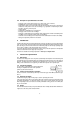
1 2 3 4 5 5.
.2.1 Do not go near leaks! - High pressure oil easily punctures skin causing serious injury, gangrene or death! - If injured, seek emergency medical help! Immediate surgery is required to remove oil! - Do not use finger or skin to check for leaks! - Lower load or relieve hydraulic pressure befor loosening finttings! 5.3 - Storage of hoses Hoses are subject to a natural aging even if they are stored correctly. Therefore, their storage and service time is limited.
5.6 - Examples for possible defects of hoses Damages of the surface and the interior (e.g. chafe marks, cuts or fissures). Embrittlement of the surface (fissuration of the hose material). Deformations, which are not in accordance with the natural shape of the hoses, in pressureless condition or under pressure or in case of bendings, e.g. separation of material layers, blister formation, squeezing or break spots. Leakage points. Instructions for installation were not observed.
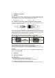
8 Connection of the tool 8.1 Hydraulic Two short hoses (each 0.5 m long) are fitted to the tool; they are connected with the motor pump via a hose pair (5 m / 10 m / 20 m, as is necessary). All hoses are colour marked and have quickconnect couplings so that they can be connected without the risk of mix-up: HP = High pressure ——> red 8.
Note: Before working on the motor pump or for coupling/decoupling the hoses, make sure that the motor pump is switched off (electric connection) or disconnected from the mains and that the lines are unpressurized. 9.2 Operating of the star grip 1 Opening of the arms: Rotate star shape ring 1 to the right hand side and hold it in this position. Closing of the arms: Rotate star shape ring 1 to the left hand side and hold it in this position.
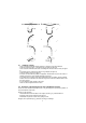
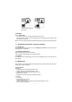
Grip area too small. Tips may break away. Safe grip. 10.4 Pulling 10.4.1 Safety advise - The chains may only be used for pulling with the rescue device. - When pulling using a chain, make sure that bolt and hook are properly accommodated, so that the chain does not slip off. 10.4.2 Fix the chain set provided for the individual tool properly as per chain set operating manual. 11 Dismantling of the device / Stop after operation 11.
Hoses • check according safety instructions for hoses (see item 5) • Check for oil leakage Function testing • Perfect opening and closing with the star grip valve. 13 Repairs 13.1 General Servicing must be carried out only by the device manufacturer or by personnel trained by the manufacturer or the authorised LUKAS dealers.
and load test. For this purpose, LUKAS offers a test kit as appropriate equipment. 13.2.4 Change of hydraulic oil - after 200 uses, latest after 2 years, the hydraulic oil has to be changed. - in any case if the oil of the pump (motor / hand pump) which belongs to the unit is changed. By changing the used oil, it should be avoided that the new oil is polluted by the used oil of the rescue tool. Procedure: The rescue tool is in closed (retracted) position • Change of oil has to be effected at the pump.
13.3.3 Change of protection boot The rubber protection boot shall protect the operator against injuries caused by the moving levers. If the boot is damaged it has to be replaced. Procedure: Remove the carrying handle (held by 2 screws) • Dismount cutter blades / blade arms (see 13.3.1) • pull the faulty boot from the cylinder body and place the new one properly, i.e. that the carrying handle fixing screws go easily through the corresponding holes in the boot. Mount and tighten carrying handle. 13.3.
15 Technical data Type Ref. No. Dimensions l x w x h (mm) without connection hoses Blade opening min. (mm) Spreading force (kN) in all operating ranges Spreading distance min. (mm) Weight incl. oil filling (kg) Operating pressure (MPa) Necessary oil quantity (l) 1 prEN 13204 TÜV (DIN 14751) French standard NFS 61-571 * 1 LKS 35 EN 84150/6239 LKS 20 EN 84150/6215 LKS 10 84150/1360 755 x 199 x 163 605 x 170 x 142 405 x 112 x 95 265 154 48 93 93 360 13.7 235 9.5 63* 0.025 UHCT 20 C 0.
15.3 Oil recommendations For LUKAS hydraulic devices, use mineral oil in accordance with DIN 51 524 and others Range of oil temperature Viscosity rating A B - 24 ... + 30 °C - 18 ... + 50 °C HL 5 HLP 10 C D - 8 ... + 75 °C + 5 ... + 80 °C HLP 22 HLP 32 E - 8 ... + 70 °C HF - E 15 Remarks biodegradable Recommended viscosity range: 10 ... 200 mm²/s, delivered with HLP 22 to DIN 51 524 15.