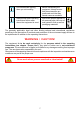
Operating instructions for rescue equipment Electrically insulated Cutters and Combi Tools 2 3 LKS 35 FI: 7 1 8 9 14 Mono-coupling system: 4 10 Quick-disconnect coupling system: 1 7 8 9 2 6 LS 330 FI: 3 12 11 4 LS 311 FI: 13 5 1 2 3 4 5 6 7 Star grip Tool body Handle Protection hose Blade arm Combi blade arm Handhold 8 9 10 11 12 13 14 Pressure hose line Return hose line Mono-coupling nipple Plug coupling nipple Plug coupling sleeve Protection box for plug coupling Protection box for
Contents Page 1. Hazard classes 4 2. Product safety 5 3. Proper use 8 4. Description of the functions 9 4.1 Description 9 4.2 Circuit diagram 9 4.3 Control of working movements 9 4.4 Hydraulic supply 10 4.5 Hose lines 10 5. Connecting the equipment 10 5.1 General points 10 5.2 Coupling the mono-couplings 11 5.3 Coupling the plug couplings 12 6. Operation 13 6.1 Preparatory actions 13 6.2 Operating the star grip (Item 1 on cover sheet) 13 7.
12. Technical Data 24 12.1 Cutting tools 24 12.2 Combi tools 26 12.3 Tightening torques for pivot bolt 26 12.4 Cutting performance 27 12.5 Hydraulic fluid recommendations 27 12.6 Operating and storage temperature ranges 27 13. EC Declarations of conformity 28 13.1 Cutting tools 28 13.2 Combi tools 30 14.
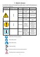
1. Hazard classes We distinguish between various categories of safety notes. The table below gives you an overview of the assignment of symbols (pictograms) and key words to the specific hazard and possible consequences.
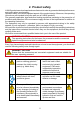
2. Product safety LUKAS products are developed and manufactured in order to guarantee the best performance and quality when used properly. Operator safety is the most important aspect of the product design. Moreover, the operating instructions are intended to help the safe use of LUKAS products. The generally applicable, legal and other binding regulations pertaining to the prevention of accidents and protection of the environment apply and are to be implemented in addition to the operating instructions.
In the event of malfunctions, immediately deactivate the equipment and secure it. The malfunction is to be repaired immediately. Do not carry out any changes (additions or conversions) to the equipment without obtaining the prior approval of LUKAS. Observe all safety and danger notes on the equipment and in the operating instructions. All safety and danger notes on the equipment are to be kept complete in a legible condition.
Ensure adequate lighting when you are working. Before transporting the equipment, always ensure that the accessories are positioned such that they cannot cause an accident. Always keep these operating instructions within reach where the equipment is used.
3. Proper use The electrically insulated LUKAS "LKS" combi tools and electrically insulated LUKAS "LS" cutters are designed specifically for rescuing victims of traffic, rail or air accidents and for making rescues from buildings. They serve the purpose of freeing injured people in accidents e. g. by cutting doors, roof bars and hinges. By using the LUKAS combi tools, trapped persons can also be freed e. g. by spreading doors and / or by removing obstacles with the aid of a chainset.
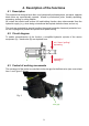
4. Description of the functions 4.1 Description The equipment is designed such that, via a hydraulically activated piston, two equal, opposite blade arms are symmetrically opened / closed by mechanical joints, thereby spreading, squeezing, pulling or cutting objects. All cutters and combi tools ensure full load-holding function when disconnected from the hydraulic supply (e. g. when being unintentional decoupled; defective hose, and so on).
4.4 Hydraulic supply A LUKAS motor pump or hand pump only may be used to drive the equipment. If the pump unit is a different make, you must make sure that it complies with LUKAS specifications, otherwise potential dangers may occur which are not the responsibility of LUKAS. Ensure in particular that the authorised operating pressure for LUKAS equipment is not exceeded. REMARK: Before you use pumps from a different manufacturer, you must contact LUKAS or an authorised dealer. 4.
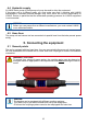
WARNING / CAUTION! Before connecting the equipment you have to pay attention that all used components are suitable to the max operation pressure of the pump unit! In the case of doubt you have to inquire LUKAS directly! 5.2 Coupling the mono-couplings The equipment is connected to the hydraulic pump via mono-coupling halves (male and female).
5.3 Coupling the plug couplings The equipment is connected to the hydraulic pump via quick-disconnect-coupling halves (male and female). X Y Before coupling unlock the connect socket by turning the sleeve into position X. Retract sleeve and connect plug and socket. Release sleeve and turn it into position Y. The connection has now been established and secured. Uncoupling is done in the reverse order.
6.1 Preparatory actions 6.1.1 6. Operation Initial commissioning Before commissioning and following repairs, the equipment must be deaerated. - Connect the equipment to the hydraulic pump (see chapter “Connecting the equipment”). - Open / close the blade arms of the equipment without any load at least twice (see chapter “Operation of the star grip”).
7. Cutting, spreading, pulling and squeezing 7.1 Safety instructions Before rescue works can commence, the position of the obstacle must be stabilised. You must ensure an adequate substructure and / or adequate support of the object. World-wide, safety guidelines pertaining to the specific country are to be observed and complied with. In the Federal Republic of Germany, regular safety inspections according to the GUV legal accident insurance regulations (Gesetzlichen Unfallversicherung) are mandatory.
During cutting, the gap between the blade tips (in the crosswise direction) may not be exceeded, otherwise the blade is in danger of breaking: Cutter / combi tool LS 311 FI STREAM LS 330 FI STREAM LKS 35 FI STREAM max. gap on the blade tips [mm] / [in.] 3 / 0.12 3 / 0.12 3 / 0.12 CAUTION! Avoid cutting particularly high-strength parts of the vehicle’s bodywork (e.g. side-impact protection): this almost always causes damage to the cutter / combi tool! 7.
7.4 Pulling (combi tools only) You may only use LUKAS chain sets for pulling purposes. Before the pulling process can be performed, ensure that the bolt and hook fit correctly to prevent the chain from slipping. Only chain sets in perfect condition may be used! The pull chains are to be inspected at least once per year by an expert! See separate operating instructions for the relevant LUKAS chain set in order to correctly attach, affix and use the chain sets.
8. Dismantling the equipment / deactivation following operation 8.1 Cutting or combi tool Once work has been completed, the blade arms are to be closed so that there is a tip distance of just a few mm. This relieves the hydraulic and mechanical strain on the equipment. REMARK: Never store the cutter / combi tool with fully closed blade arms! The complete closure of the blade arms can cause hydraulic and mechanical stress to build up again.
9.1 Cutting / combi tool, complete Inspections to be carried out: Visual inspection Cutter / combi tool • Opening width of the blade arms on the tips (see chapter “Technical data”), • General tightness (leaks), • Operability of the star grip, • Existence and stability of handle, • Labels completely existent and legibly, • Covers in perfect condition, • Torque control of the pivot bolt (torque MA see "Technical data"), • Couplings must be easy to couple, • Dust protection caps must be available.
10.1 General points 10. Repairs Servicing may only be carried out by the manufacturer or personnel trained by the manufacturer and by authorised LUKAS dealers. Only LUKAS spare parts may be used to replace all components (see spare parts list) since special tools, assembly advice, safety aspects, inspections might have to complied with (see also chapter “Maintenance and Service”).
10.2 Preventative service 10.2.1 Note concerning care The exterior of the equipment is to be cleaned from time to time in order to protect it from external corrosion. Oil is to be applied to the metallic surfaces. 10.2.2 Functional and loading test If there is any doubt regarding the safety or reliability of the equipment, a function and load test must also be performed. LUKAS offers appropriate test equipment to this end. 10.2.
10.3 Repairs Since repairs to the electrically insulated rescue tools must always be concluded by testing and confirmation of the minimum electrical arcing resistance, repairs may only be carried out by authorised specialised dealers or by LUKAS directly. 11.
Trouble Damages on the surface of the hydraulic hoses Control Hydraulic fluid leaks on the piston rod Leak on the handhold Increase load? (combi tool when spreading) Cause Solution Mechanical Replace hoses damages or contact with aggressive agents Defective rod seal Repair by an authorised dealer, by personnel specially Damage to the trained by LUKAS, or piston by LUKAS itself Secure the loads and Load increase (e.g.
Trouble Control Cause Especially by usage check the hose connection of mono-couplings: connections of the to the couplings Leak on the handhold hoses interchanged Solution reconnect the hoses to the coupling in the right way Returnline disabled with mono-couplingsystem: Leak in the couplings with quickdisconnect-couplingsystem: Leak in the couplings Is the coupling damaged? disconnect the returnline from the coupling, clean it and reconnect it.
12. Technical Data Since all values are subject to tolerances, minor differences may occur between the data on your equipment and the data in the following schedules! 12.1 Cutting tools type LS 330 FI STREAM LS 330 FI STREAM 112070000 172070000 ref.no. dimensions l x w x h (w/o connection hoses) max. cutting opening 733 x 210 x 195 [in.] 28.85 x 8.27 x 7.68 [mm] 228 [in.] 8.98 max. cutting force (rear end of the cutting surface) [kN] 616 [lbf.] 138,489 weight incl.
type LS 311 FI STREAM LS 311 FI STREAM 112075000 172075000 ref.no. dimensions l x w x h (w/o connection hoses) 697 x 210 x 195 [in.] 27.44 x 8.27 x 7.68 [mm] 150 [in.] 5.91 max. cutting force (rear end of the cutting surface) [kN] 642 [lbf.] 144,335 weight incl. hydraulic fluid [kg] 16,9 [lbs.] 37.26 max. cutting opening max. operating pressure min. needed volume of hydraulic fluid coupling system * ** [mm] [Mpa] * 70 [psi.] 10,153 [l] ** 0,098 [gal.-US] 0.
12.2 Combi tools type ref.no. LKS 35 FI LKS 35 FI 113070000 173070000 [mm] dimensions l x w x h (w/o connection hoses) 762 x 210 x 195 [in.] 30.00 x 8.27 x 7.68 [mm] max. cutting opening 265 [in.] 10.43 [kN] max. cutting force (rear end of the cutting surface) [lbf.] 93,975 [mm] max. spreading distance (on the blade tips) weight incl. hydraulic fluid min. needed volume of hydraulic fluid 14.17 [kN] 49,5 [lbf.] 11,129 [kg] 17,0 [lbs.] 37.5 [Mpa] * 70 [psi.
12.4 Cutting performance Cutting material Cutting material dimensions LS 311 FI LS 330 FI LKS 35 FI max. max. max. [mm] [mm] [mm] [in.] [in.] [in.] Round material steel (acc. to EN 13204) 33 33 30 1.30 1.30 1.18 Round material steel (acc. to NFPA 1936) 33 33 30 1.30 1.30 1.18 12.5 Hydraulic fluid recommendations Mineral oil DIN ISO 6743-4 for LUKAS hydraulic equipment and others Oil code HM 10 Viscosity rating VG 10 Remarks A Oil temperature range -20 ....
13. EC Declarations of conformity 13.
13.
14.
Please dispose all packaging materials and dismantled parts properly LUKAS Hydraulik GmbH A Unit of IDEX Corporation Tel.: (+49) 0 91 31 / 698 - 0 Fax.: (+49) 0 91 31 / 698 - 394 e-mail: lukas.info@idexcorp.com www.lukas.com Made in GERMANY FI_Geräte_BA_GB_172075085_1010.