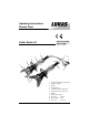
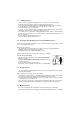
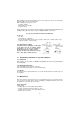
Operating Instructions Rescue Tools 84150/1334-85 GB Issue 04.2006 Cutter Series LS replaces 08.2005 1 3 11 2 10 9 4 5 7 6 1 2 3 4 5 6 1 8 Control valve with star shape ring Hydraulic cylinder Handle Protecting hose Central bolt with selflocking nut Cutter blades, resp.
1 Basic operation and designated use of the machine The machine has been built in accordance with state-of-the-art standards and the recognized safety rules. Nevertheless, its use may constitute a risk to life and limb of the user or of third parties, or cause damage to the machine and to other material property. 1.
.2 Before starting up or setting the machine in motion and during operation of the machine make sure that nobody is at risk. 3.3 Before transporting the machine always check that the accessories have been safely stowed away. 3.4 Make sure that there is enough lighting during work. 3.5 Avoid any operation that might be a risk to machine stability. 3.6 Check the machine at least after every operation for obvious damage and defects. Report any changes (incl.
5 Safety Instructions for Hydraulic Hoses ATTENTION! - by no means the hose must be exposed to brake fluid as this fluid will destroy outer layer of hose - do not expose the hose to any of the following aggressive fluids: • acid, lye or solvent • alcohol and fuel • battery and automatic transmission fluid • phosphate ester Clean hose immediately with water and detergent when it was exposed to such fluids.
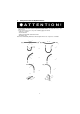
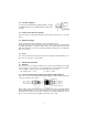
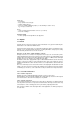
.1 - Handling of hoses never exceed the permissible working pressure as stated on hose and/or literature avoid any tension (see figure 1) and do not hang any load onto the hose never exceed the minimum bend radius as resulting kink will cause failure of hose (see figure 2) do not allow hose to contact sharp edges or rough objects (see figure 3) avoid any twisting of hose (see figure 4) do not run over hose with any vehicle or equipment ! Hoses which are put on the surface of sidewalk or street have to be
5.5 Inspection and replacement intervals of hoses - After each operation the hoses have to be checked for external damages, cracks, kinks and bubbles! - The operator has to replace the hoses in appropriate period of times, even if there are no visible security defects on the hoses. - The hoses have to be replaced 10 years as from date of manufacture at the latest (see marking on the hose)! Hoses are subject to a natural aging even if they are stored correctly.
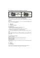
.2 Connection diagram For your better understanding the hydraulic diagram is showing in simplified manner the tool's hydrauliccylinder (A) with control valve (B). 7.3 Control of movements in operation The arm movement is controlled by the firmly mounted star grip control valve (see cover page item 1). 7.4 Hydraulic oil supply LUKAS motor/engine pump or hand pump is used for operating the devices.
Note regarding the modified release mechanism as of June 2004 When connecting the hoses, be aware of the following basic functions of the quick couplers: X Y Before coupling unlock the connect socket by turning the sleeve into position X. Retract sleeve and connect plug and socket. Release sleeve and turn it into position Y. Now the connection has been made and locked. Uncoupling is done in the reverse order. Connection of the hoses is possible only, when they are depressurized.
When working in an environment which involves a risk of explosions, do not use motor/engine powered pumps. Instead, use hand pumps. When operating rescue devices, wear - protective clothing - helmet with visor or goggles - protective gloves. During operation of the cutter, parts of the object worked on may break away and endanger people standing nearby. Onlookers must be kept at a safety clearance of at least 5m. Do not get your hands in between the blade arms.
Cutter unit • No leakages • Easy operation of the star grip • Handle existing and fast • Check of central bolt tightening torque (see also drawing to Section 13.3.1) MA = Torque (see item 15.2) Hoses • check according safety instructions for hoses (see item 5) • Check for oil leakage Function testing • Perfect opening and closing with the star grip valve. 13 Repairs 13.
Parts with insignificant wear (fretting marks) can be repaired by polishing and fitted again after greasing. More pronounced wear marks require replacement of the damaged parts (by pairs). At these intervals, crack testing of the cutter blades is equally mandatory. For this purpose, a special crack test kit is available. To protect the device against external corrosion clean its surface from time to time and slightly grease it with oil. 13.2.
13.3.2 Oil spill out of the control valve handle (see cover page item 7) Pressure or return hose are not tightened properly. Procedure: Loosen the 2 allen screws (SW5) inside the handle sleeve and remove them together with the short plastic isolation sleeves. Pull handle sleeve backwards until the hose connection points become visible and retighten the retaining nut. Change hose connection sealing rings if necessary. Place handle sleeve again and tighten it with the 2 allen screws.
14 Troubleshooting Trouble Hoses cannot be coupled On actuating blades move slowly or by jerks No pressure build-up Check Hoses correctly connected power pack operating Star grip doesn't return to middle position when released Oil leakage out of hoses or hose fittings Surface of hydraulic hoses is dissolved Blades spread up at tips to a gap of more than 3 mm even if not fully loaded Leakages on the piston rod Cause Pressurized Remedy Relieve pump pressure Air in the hydraulic system Thoroughly vent pu
15.1 Cutting performance / cutting forces Type of Form of Strength material material Rm (N/mm2) Dimension of material LS 131 EN LS 200 EN LS 301 EN mm mm mm 600 (500) 750 (Ø 24) Ø 20 450 60 x 5 40 x 40 x 4 Steel 400 Alu LS 330 EN mm Ø 30 Ø 25 Ø 28 80 x 10 40 x 40 x 4 80 x 8 55 x 55 x 4 110 x 10 60 x 60 x 4 40 x 30 x 4 35 x 3 60 x 30 x 6 65 x 40 x 5 80 x 40 x 6 65 x 40 x 6 Ø 42.6 x 2,6 Ø 26 Ø 114 x 4.5 Ø 30 Ø 72.3 x 3.2 Ø 32 Ø 84.3 x 3.
© Copyright 2003 LUKAS Hydraulik GmbH LUKAS Hydraulik GmbH A Unit of IDEX Corporation Weinstraße 39, 91058 Erlangen • Germany Postfach 2560, 91013 Erlangen • Germany Telefon (09131) 698-0 • Telefax (09131) 698-394 E-mail: info@lukas.de Schneidgeräte_BA_DRUCK_841501334_0406.