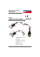
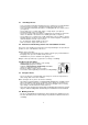
Operating Instructions Rescue Tools Cutters LS501EN, LS511EN, LS530EN 84150/1211-85 GB Ausgabe 05.2006 8 9 1 2 5 4 9 6 11 7 10 11 3 7 1 LS501EN 2 1 2 9 4 5 3 8 6 7 4 11 5 3 10 LS530EN 6 1 2 3 4 5 6 7 8 9 10 11 Control valve with star shape ring Hydraulic cylinder Handle Protecting hose Central bolt with selflocking nut Cutter blades, resp.
Content Page 1 Basic operation and designated use of the machine 3 2 Organizational measures 3 3 General safety instructions 3 4 Instructions for maintenance and service 4 5 Safety Instructions for Hydraulic Hoses 5 6 Intended use 7 7 Function and performance 7 8 Connection of the tool 8 9 Operation 9 10 Cutting 9 11 Dismantling of the device / Stop after operation 10 12 Maintenance 10 13 Repairs 11 14 Troubleshooting 14 15 Technical data 15 2
1 Basic operation and designated use of the machine 1.1 The machine has been built in accordance with state-of-the-art standards and the recognized safety rules. Nevertheless, its use may constitute a risk to life and limb of the user or of third parties, or cause damage to the machine and to other material property. 1.
3.2 Before starting up or setting the machine in motion and during operation of the machine make sure that nobody is at risk. 3.3 Before transporting the machine always check that the accessories have been safely stowed away. 3.4 Make sure that there is enough lighting during work. 3.5 Avoid any operation that might be a risk to machine stability. 3.6 Check the machine at least after every operation for obvious damage and defects. Report any changes (incl.
Safety Instructions for Hydraulic Hoses ATTENTION! - by no means the hose must be exposed to brake fluid as this fluid will destroy outer layer of hose - do not expose the hose to any of the following aggressive fluids: • acid, lye or solvent • alcohol and fuel • battery and automatic transmission fluid • phosphate ester Clean hose immediately with water and detergent when it was exposed to such fluids.
5.
5.5 Inspection and replacement intervals of hoses - After each operation the hoses have to be checked for external damages, cracks, kinks and bubbles! - The operator has to replace the hoses in appropriate period of times, even if there are no visible security defects on the hoses. - The hoses have to be replaced 10 years as from date of manufacture at the latest (see marking on the hose)! Hoses are subject to a natural aging even if they are stored correctly.
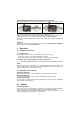
7.2 Connection diagram For your better understanding the hydraulic diagram is showing in simplified manner the tool's hydrauliccylinder (A) with control valve (B). 7.3 Control of movements in operation The arm movement is controlled by the firmly mounted star grip control valve (see cover page item 1). 7.4 Hydraulic oil supply LUKAS motor/engine pump or hand pump is used for operating the devices.
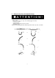
Note regarding the modified release mechanism as of June 2004 When connecting the hoses, be aware of the following basic functions of the quick couplers: X Y Before coupling unlock the connect socket by turning the sleeve into position X. Retract sleeve and connect plug and socket. Release sleeve and turn it into position Y. Now the connection has been made and locked. Uncoupling is done in the reverse order. Connection of the hoses is possible only, when they are depressurized.
When operating rescue devices, wear - protective clothing - helmet with visor or goggles - protective gloves. During operation of the cutter, parts of the object worked on may break away and endanger people standing nearby. Onlookers must be kept at a safety clearance of at least 5m. Do not get your hands in between the blade arms.
Cutter unit • No leakages • Easy operation of the star grip • Handle existing and fast • Check of central bolt tightening torque (see also drawing to Section 13.3.1) MA = Torque (see item 15.2) Hoses • check according safety instructions for hoses (see item 5) • Check for oil leakage Function testing • Perfect opening and closing with the star grip valve. 13 Repairs 13.
Parts with insignificant wear (fretting marks) can be repaired by polishing and fitted again after greasing. More pronounced wear marks require replacement of the damaged parts (by pairs). At these intervals, crack testing of the cutter blades is equally mandatory. For this purpose, a special crack test kit is available. To protect the device against external corrosion clean its surface from time to time and slightly grease it with oil. 13.2.
.3.2 Oil spill out of the control valve handle (see cover page item 7) Pressure or return hose are not tightened properly. Procedure: Loosen the 2 allen screws (SW5) inside the handle sleeve and remove them together with the short plastic isolation sleeves. Pull handle sleeve backwards until the hose connection points become visible and retighten the retaining nut. Change hose connection sealing rings if necessary. Place handle sleeve again and tighten it with the 2 allen screws.
Troubleshooting Trouble Hoses cannot be coupled Check Cause Pressurized Remedy Relieve pump pressure On actuating blades Hoses correctly move slowly or by connected, jerks power pack operating Air in the hydraulic system Thoroughly vent pump unit: see 9.1.1 No pressure build-up Not enough oil in hand resp. motor pump. Vent pump after changing oil. Refill oil and vent the system (see operating instruction 9.1.
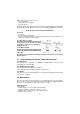
Technical data Type LS 501 EN LS 511 EN LS 530 EN Ref. no. 84150/1231 84150/1211 84150/1236 772x245x170 740x255x170 775x235x165 Dimensioons l x w x h without connection hoses (mm) Opening at the tips (mm) 180 150 283 Weight incl. oil filling (kg) 19,3 18,8 17,9 Operating pressure (MPa) * Necessary oil quantity (l) 1 max.
15.4 LUKAS Hoses Bending radius Burst resistance Temperature resistance Operating medium Rmin = 38 mm safety factor: burst pressure / max. operating pressure, min. 4 : 1 - 40°C ... + 100°C Mineral oil according to DIN 51524 15.5 Others Working temperature Ambient temperature (power pack in operation) Storage temperature (power pack not in operation) -20 ... +55°C -24 ... +45°C -30 ...