Operating Instructions Recycling System 84150/1390-85 GB Issue 08.2006 Cutter LSI 600 / 400 replaces 8.
Content Page 1 Correct use of the device 3 2 Organisational measures 3 3 General safety instructions 4 4 Maintenance and servicing instructions 5 5 Safety instructions for hose lines 6 6 Indented use 8 7 Description 8 8 Connection of the devices 9 Operation 10 10 Dismantling of the device / Stop after operation 12 11 Maintenance 12 9 12 Repairs 13 13 Troubleshooting 17 14 Technical data 18 2
1 Correct use of the device 1.1. The device has been constructed according to the latest technology and the recognised safety regulations. However, danger to life or limb can arise for the operator or third parties occur during use or the device and other items can be damaged. 1.2. Only use the device in perfect condition and according to the instructions, safely and safety conscious! Immediately repair (or arrange repair of) malefunctions which can affect safety! 1.
2.6 The operating pressure marked on the device must not be exceeded. 2.7 Only original LUKAS parts and original LUKAS accessories and system components should be used for repairs. 2.8 Prescribed and named deadlines for tests/inspections as stated in the operating instructions must be observed. 2.9 Properly dispose of all packaging materials and removed parts. 3 General safety instructions 3.1 In the event of a malfunction, immediately shut off and secure the device. Repair (arrange repair) immediately.
3.12 The generation of an electrostatic charge producing sparks as a possible consequence should be avoided when working with the device. 3.13 When working with or storing the device, ensure that the function and safety of the device are not affected by large external temperature effects and that it is not damaged. Please note that the device can heat up as a result of prolonged use. 3.14 Safety equipment must never be disconnected. 3.15 Never work when overtired or inebriated. 3.
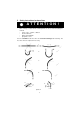
5 Safety instructions for hose lines ATTENTION ! - The hoses must never come into contact with brake fluid. After coming to contact with the following fluids, the hoses must immediately be cleaned: • • • • acids, soaps, solutions / diluted alcohol and fuels battery acids and ATF phosphate esters It is also essential that the hose lines are checked for damage after cleaning. The hose lines must be replaced if necessary.
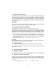
5.1 Handling instructions for hose lines - The defined operating pressure must not be exceeded. The hoses must not be subjected to tension and torsion (see picture 2, fig. 1). The hose line must not be bent (see picture 2, fig. 2). Do not pull or lay hoses across edges (see picture 2, fig. 3). Do not connect twisted hoses (see picture 2, fig. 4). Never drive a vehicle over the hoses. Loose hose lines laid on roads and paths must be protected against damage, e.g. with hose bridges (see picture 2, fig. 5).
5.5 Periods for checking and replacing hose lines - Check the hose lines for external damage, tears, bends and inflating after every use. The operator must ensure that hose lines are replaced at reasonable intervals, even if no safety deficiencies can be detected on the hose.
7.3 Hydraulic power package A LUKAS motor pump of PO6... LSI series is to be used for operating the devices. If the power pack comes from a manufacturer other than LUKAS, it must be ensured that it fulfills the LUKAS specifications (see connection diagram), as otherwise dangers may occur for which LUKAS cannot be held liable. Especially it has to be made sure that the permissible working pressure of 50 MPa (500 bar) is without consultation with LUKAS not exceeded. 7.
8.2 Connection of the plug-in coupling counterparts for HP and R hoses The device is connected to the hydraulic pump with the plug-in coupling counterparts (plug and socket), there being no risk of mix-up. Before coupling, remove the dust protection covers and unlock the connect socket with adjusting ring by turning it. Withdraw the sleeve and connect plug and socket while holding the sleeve in this position. Release the sleeve and set the showglass to „red“ with the adjusting ring.
Note: Before working on the pump power pack or for coupling/decoupling the hoses, make sure that the pump power pack is switched off (electric connection) or disconnected from the mains and that the lines are unpressurized. 9.1.
10 Dismantling of the device / Stop after operation 10.1 Cutter unit After operation, close the blades to a tip distance of a few mm. This relaxes the unit hydraulically and mechanically. 10.2 Hydraulic power pack Stop the hydraulic power pack after operation. 10.3 Hoses Uncouple the red hose first and the blue hose second as described under 8.3. Put dust caps over the couplings. 10.4 Electric lines During longer breaks, the electric lines should be disconnected. 11 Maintenance 11.
11.3 Fixture in manipulator • Perfect condition of chucking and fixture of the device. • Easy operation of rotating sleeve. 11.4 Electric elements • Check of electric connections / couplings. • Perfect function of actuating switch. 12 Repairs 12.1 General Servicing should only be carried out by the manufacturer of by staff trained by the manufacturer and by authorised LUKAS dealers.
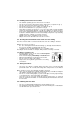
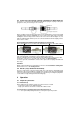
Lubricate the cutter with a grease gun with LUKAS special grease as shown in the picture right. Excess grease on the lubrication nipple (see left) after lubrication should be removed and disposed of professional. Attention! When working with upturned blades, in particular, please ensure that no coarse fragments reaches the mechanical parts under the hand guard of the device. Moveable parts of the device could be blocked as a result and even be destroyed.
2.2.2 Main checks The mechanical transfer elements on the device are subject to very high mechanical stresses and therefore they must be checked after 500 operating hours at latest. Thereby, appearances of attrition can be detected early so that breakages can be avoided by timely replacement of these worn parts. Perfect parts can be reassembled after careful lubrication with LUKAS special grease.
Attention: Thoroughly clean all sliding surfaces before assembly and grease with LUKAS special grease. Note: Defective parts (blades, bolts, sliding plates) should always be replaced as pairs. If you detect, when changing blades, that the levers are damaged (see 12.3.1), their fit holes are deformed, fretting marks exist or they are otherwise damaged, these must be replaced too. This repair must be carried out by an authorised LUKAS dealer or by the LUKAS service department. 12.3.
13 Troubleshooting Trouble Check Hoses cannot be coupled Blades move slowly Hoses correctly or by jerks when connected, power actuated pack operating No pressure build-up Cause Pressurized Remedy Relieve pump pressure Air in the hydrallic Thorougly vent system pump unit Oil leakage out of hoses or hose fittings Surface of the hydraulic hoses is dissolved Blades spread up at tips to a gab of more than 3 mm Leakages: leaks at the piston rod Insufficient oitl in the hand or motor pump.
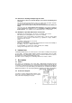
14 Technical data Type LSI 600 Dimensions lxwxh (mm) LSI 600E LSI 400E 481x210x126 684x252x126 684x252x126 Weight (incl. oil filling) (kg) 20 22 14,3 Control voltage with integral switch (V) - 24 Protective system switch / cable / plug - IP 54 max.
14.2 Central bolt / Torque Type Central bolt Torque (Nm) LSI 600/600E / LSI 400/400E M 27 x 1,5 (SW 41) 130 + 10 14.3 Oil recommendations For LUKAS hydraulic devices, use mineral oil in accordance with DIN 51 524 and others Range of oil temperature Viscosity rating A -24 .... +30°C HL 5 B -18 .... +50°C HLP 10 C -8 .... +75°C HLP 22 D +5 .... +80°C HLP 32 E -8 .... +70°C HF - E15 Remarks biodegradable Recommended viscosity range: 10 ... 200 mm²/s, delivered with HLP 22 to DIN 51 524.