Operating Instructions Recycling system Cutter LSI 501, LSI 511, LSI 530, LSI 55 9 84150/1490-85 GB Issue 07.
Content Page 1 Correct use of the device 3 2 Organisational measures 3 3 General safety instructions 4 4 Maintenance and servicing instructions 5 5 Safety instructions for hose lines 6 6 Functions and performance 8 7 Connecting the device 9 8 Operation 11 9 Cutting 13 10 Dismantling of the device / switching off after use 14 11 Maintenance 14 12 Repairs 15 13 Troubleshooting 19 14 Technical data 20 2
1 Correct use of the device 1.1. The device has been constructed according to the latest technology and the recognised safety regulations. However, danger to life or limb can arise for the operator or third parties occur during use or the device and other items can be damaged. 1.2. Only use the device in perfect condition and according to the instructions, safely and safety conscious! Immediately repair (or arrange repair of) malefunctions which can affect safety! 1.
2.6 The operating pressure marked on the device must not be exceeded. 2.7 Only original LUKAS parts and original LUKAS accessories and system components should be used for repairs. 2.8 Prescribed and named deadlines for tests/inspections as stated in the operating instructions must be observed. 2.9 Properly dispose of all packaging materials and removed parts. 3 General safety instructions 3.1 In the event of a malfunction, immediately shut off and secure the device. Repair (arrange repair) immediately.
3.12 The generation of an electrostatic charge producing sparks as a possible consequence should be avoided when working with the device. 3.13 When working with or storing the device, ensure that the function and safety of the device are not affected by large external temperature effects and that it is not damaged. Please note that the device can heat up as a result of prolonged use. 3.14 Safety equipment must never be disconnected. 3.15 Never work when overtired or inebriated. 3.
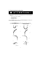
5 Safety instructions for hose lines ATTENTION ! - The hoses must never come into contact with brake fluid. After coming to contact with the following fluids, the hoses must immediately be cleaned: • • • • acids, soaps, solutions / diluted alcohol and fuels battery acids and ATF phosphate esters It is also essential that the hose lines are checked for damage after cleaning. The hose lines must be replaced if necessary.
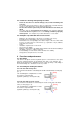
5.1 Handling instructions for hose lines - The defined operating pressure must not be exceeded. The hoses must not be subjected to tension and torsion (see picture 2, fig. 1). The hose line must not be bent (see picture 2, fig. 2). Do not pull or lay hoses across edges (see picture 2, fig. 3). Do not connect twisted hoses (see picture 2, fig. 4). Never drive a vehicle over the hoses. Loose hose lines laid on roads and paths must be protected against damage, e.g. with hose bridges (see picture 2, fig. 5).
5.5 Periods for checking and replacing hose lines - Check the hose lines for external damage, tears, bends and inflating after every use. The operator must ensure that hose lines are replaced at reasonable intervals, even if no safety deficiencies can be detected on the hose.
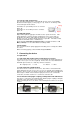
6.2.3 LSI cutter with cylinder bottom The cutter with cylinder bottom is controlled with pressure to the correspondingly labelled connection nipple (see first page pos. 10). Control is not directly on the tool, but through external controls. cutting The blades are opened with pressure to connector nipple „B“. The blades are closed with pressure to connector nipple „A“. open 6.3 Hydraulic power Only LUKAS hydraulic aggregate should be used to operate the device.
Before connecting, withdraw and hold the locking socket (position X). Connect the nipple and socket and release the locking socket. Then turn the locking cover to position Y. The connection has now been made and secured. Decoupling is carried out in reverse. It is only possible to connect the device if the hoses are depressurised. The supplied dust covers are used to protect against dust.
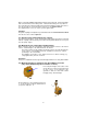
Then fix the LSI cutter to the swivel hanger (see picture left). Note: The device cannot be clamped tighter in the hanger! This is because the cutter is pivoted in the swivel hanger. 2 The swivel hanger has 2 holes in order to equalise differences in center of gravity (see picture left, pos. 2) by fixing the clevis into the second hole. The LSI cutter should now be hanging vertically aligned to the steel cable (see picture right).
8.2 Operating the 4/3-way valve with the star grip Open device (extend): Turn the star grip clockwise and hold in this position until the blades reach the desired opening width. Do not hold the star grip in this position if the blades have already reached their maximum position. Close device (retract): Turn the star grip counterclockwise and hold in this position until the blades reach the desired opening width or until the blades are closed completely.
9 Cutting 9.1 Safety instructions - Woldwide all national safety guidelines must be observed and complied. If there is a explosion risk, do not use motor pumps because of sparks. In such cases, manual pumps must be used. When working with the cutter, you must wear: work or protective clothing, Helmet with visor or goggles, Gloves Before using the cutter, ensure that the movement of the blades does not represent a danger to persons or objects as a result of blade movement or catapulted cut materials.
10 Dismantling the device / switching off after use 10.1 Cutter After end of working, the blades should be closed till a few mm of tip distance. This releases the entire device in terms of the hydraulics and mechanically. 10.2 Hydraulic aggregate After end of working, the engine must be shut down. 10.3 Hose lines First disconnect the high pressure hose (red), then the return hose (blue) as described under 7.2. Attach the dust caps to the plug connections. 10.
12 Repairs 12.1 General Servicing should only be carried out by the manufacturer of by staff trained by the manufacturer and by authorised LUKAS dealers. Only components, which are available as original LUKAS spare parts, may be exchanged, because possibly there must be observed necessary special tools, assembly instructions, safety aspects or tests. Therefore use only original LUKAS spare parts.
Attention! When working with upturned blades, in particular, please ensure that no coarse fragments reaches the mechanical parts under the hand guard of the device. Moveable parts of the device could be blocked as a result and even be destroyed. The device must be checked for dirt and impurities in the mechanical part after each of such applications, and cleaned if necessary. illustration 1 Unscrew handle and pull back the hand guard according to illustration 1.
12.2.3 Function and load test If there are doubts about the safety and reliability, an additional function and load test must be carried out. For that purpose LUKAS offers a test equipment. 12.2.4 Changing the hydraulic oil - Change the hydraulic oil after approx. 500 operating hours, but after 2 yeas at latest; - Whenever the oil of the appropriated pump (motor / hand pump) is changed. Mixing the cutters used oil with fresh oil must be avoided because of impurity.
Note: Defective parts (blades, bolts, sliding plates) should always be replaced as pairs. If you detect, when changing blades, that the levers are damaged (see 12.3.1), their fit holes are deformed, fretting marks exist or they are otherwise damaged, these must be replaced too. This repair must be carried out by an authorised LUKAS dealer or by the LUKAS service department. 12.3.2 Loss of oil at the hand hold (first page, pos.
13 Troubleshooting Trouble Check Hoses cannot be coupled Blades move slowly Hoses correctly or by jerks when connected, power actuated pack operating No pressure build-up Star grip does not return to the middle position when released Oil leakage out of hoses or hose fittings Cause Pressurized Remedy Relieve pump pressure Air in the hydrallic Thorougly vent system pump unit Insufficient oitl in the hand or motor pump.
14 Technical data LSI 501 Typ of cutter Connection / control 4/3-way-valve Electric controls Cylinder bottom Ref. no. Dimensions l x w x h without connection hoses Opening at tips 84150/1491 84150/91491 84150/81491 789 x 235 x 168 645 x 235 x 168 (mm) 789 x 235 x 168 180 (mm) Weight incl. oil filling (kg) Operating pressure (Mpa)* 21,7 50 (l)** 0,15 Necessary oil quantity 23,5 20,4 LSI 511 Typ of cutter Connection / control 4/3-way-valve Electric controls Cylinder bottom Ref.
LSI 55 Typ of cutter Connection / control 4/3-way-valve Electric controls Cylinder bottom Ref. no. Dimensions l x w x h without connection hoses Opening at tips 84150/1494 84150/91494 84150/81494 860 x 235 x 168 626 x 235 x 168 (mm) 862 x 235 x 168 430 (mm) Weight incl.
Cutting material 22 Round bar steel (Rm 750 N/mm²) Round bar steel (Rm 550 N/mm²) Round bar aluminum (Rm 400 N/mm²) Round bar copper (Rm 200 N/mm²) U-profile steel (Rm 500 N/mm²) Flat steel (Rm 500 N/mm²) Steel pipe (Rm 500 N/mm²) Square pipe (Rm 500 N/mm²) Angle steel (Rm 500 N/mm²) LSI 501 LSI 511 LSI 530 LSI 55 max. continuous operation max. continuous operation max. continuous operation max.
14.6 Test pressures The stated reference test pressures only refers to the measurement with the LUKAS testing kit (from the LUKAS accessories programme). Measurements and thresholds with other test equipment must be agreed in advance with the LUKAS service department.