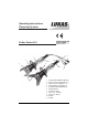
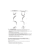
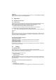
Operating Instructions Recycling System 84150/1362-85 GB Issue 12.2005 Cutter Series LSI Replaces 6.2004 8 2 7 9 6 1 5 11 10 3 4 1 2 3 4 5 6 7 8 9 10 11 Control valve with star shape ring Quick-connect socket StMu 61 - 0 Quick-connect plug StNi 61 - D Cutter blades, resp.
Content page 1 Basic operation and designated use of the machine 3 2 Organizational measures 3 3 General safety instructions 4 4 Instructions for maintenance and service 5 5 Safety Instructions for Hydraulic Hoses 5 6 Intended use 8 7 Function and performance 8 8 Connection of the tool 9 9 Operation 10 10 Cutting 10 11 Dismantling of the device / Stop after operation 11 12 Maintenance 11 13 Repairs 12 14 Troubleshooting 16 15 Technical data 17 2
1 Basic operation and designated use of the machine 1.1 The machine has been built in accordance with state-of-the-art standards and the recognized safety rules. Nevertheless, its use may constitute a risk to life and limb of the user or of third parties, or cause damage to the machine and to other material property. 1.
3 General safety instructions 3.1 In the event of malfunctions, stop the machine immediately and lock it. Have any defects rectified immediately. 3.2 Before starting up or setting the machine in motion and during operation of the machine make sure that nobody is at risk. 3.3 It is strictly forbidden to get a part of the body between the blades of the device! There is the danger of cutting! 3.
4 Instructions for maintenance and service 4.1 For the execution of maintenance and service work, tools and workshop equipment adapted to the task on hand are absolutely indispensable. Work on the hydraulic system must be carried out only by personnel having special knowledge and experience with hydraulic equipment. 4.2 Before putting into operation clean the machine, especially connections and threaded unions, of any traces of oil, fuel or preservatives before carrying out maintenance/repair.
5.
5.2.1 Do not go near leaks! - High pressure oil easily punctures skin causing serious injury, gangrene or death! - If injured, seek emergency medical help! Immediate surgery is required to remove oil! - Do not use finger or skin to check for leaks! - Lower load or relieve hydraulic pressure before loosening finttings! 5.3 Storage of hoses - Hoses are subject to a natural aging even if they are stored correctly. Therefore, their storage and service time is limited.
5.6 Examples for possible defects of hoses - Damages of the surface and the interior (e.g. chafe marks, cuts or fissures). - Embrittlement of the surface (fissuration of the hose material). - Deformations, which are not in accordance with the natural shape of the hoses, in pressureless condition or under pressure or in case of bendings, e.g. separation of material layers, blister formation, squeezing or break spots. - Leakage points. - Instructions for installation were not observed.
8 Connection of the tool 8.1 Hydraulic Two short hoses are fitted to the tool; they are connected with the motor pump via a hose pair (5 m / 10 m / 20 m, as is necessary). All hoses are colour marked and have quick-connect couplings so that they can be connected without the risk of mix-up: HP = High pressure ——> red R = reflux ——> blue. 8.
Attention! Quick couplers partly have special functions. Therefore it is not allowed screwing them off from the hoses or to exchange them. 9 Operation 9.1 Preparatory measures 9.1.1 Initial start-up Check the machine before initial start-up for obvious damage and defects. All lines, hoses and screwed connections have to be checked for leaks and obvious damage. Before initial start-up and after repairs, the device must be vented: - Connect the device to the hydraulic pump (see item 8).
10.2 Principles on cutting The blades must be applied at a right angle to the object to be cut. To enhance cutting performance, cut as close as possible to the blade fulcrum. On cutting, the gap between the blade tips must not be larger than 3 mm (Risk of blade fracture!). 10.2.1 Attention! With cutters having curved blades the blade tips must by no means be loaded with full cutting capacity. Cutting of profiles of up to 2 mm thickness is permissible.
13 Repairs 13.1 General Servicing must be carried out only by the device manufacturer or by personnel trained by the manufacturer or the authorised LUKAS dealers. For replacement on all components, use only genuine LUKAS spare parts as specified in the spare parts list, as here possibly required special tools, mounting information, safety aspects, testing must absolutely be taken into account. See section 4.
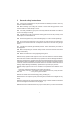
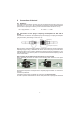
picture 2 Clean the mechanical parts (see picture 2) with compressed air from dirt and metal chips. If the upper sealing lips of the protection boot are damaged too seriously, the boot must be changed against a new one. 13.2.2 General inspections The mechanical transmission elements of the cutter unit are subjected to very high mechanical stressing and must, therefore, be inspected at certain intervals.
Procedure: The cutter tool is in closed (retracted) position • Change of oil has to be effected at the pump. Screw off the return hose at the pump: - in case of hose connection: screw off the connecting piece of the blue return hose. - in case of quick connect couplings: screw off totally the coupling nut of the quick connect coupling of the blue return hose.
Procedure: Remove the carrying handle (held by 2 screws) • Dismount cutter blades / blade arms (see 13.3.1) • pull the faulty boot from the cylinder body and place the new one properly, i.e. that the carrying handle fixing screws go easily through the corresponding holes in the boot. Mount and tighten carrying handle. 13.3.4 Carrying handle (see cover page item 11) Damaged carrying handles have to be replaced immediately.
14 Troubleshooting Trouble Check Hoses cannot be coupled On actuating blades move slowly or by jerks Hoses correctly connected power pack operating Cause Remedy Pressurized Relieve pump pressure Air in the hydraulic system Thoroughly vent pump unit: see 9.1.1 No pressure build-up Not enough oil in hand Refill oil and vent or motor pump. system (see opera ting instruction 9.1.
15 Technical data Type LSI 200 LSI 220 LSI 230 LSI 235 Dimensions lxwxh without conection hoses 670x190x163 725x190x163 737x190x163 760x190x163 (mm) Opening at tips (mm) 125 150 225 265 Weight incl. oil filling (kg) 13 14.2 15 13.8 Operating pressure (MPa) * max. 50 Useable oil quantity (l) ** 0.20 Type LSI 240 LKS 10 Dimensions lxwxh without conection hoses 750x190x163 405x112x195 (mm) Opening at tips (mm) 285 48 Weight incl. oil filling (kg) 15.2 5.3 Operating pressure (MPa) * max. 50 max.
Max. Dimensions of Material LSI 230 LSI 230 LSI 235 LSI 235 Type of Form Strength max. cutting Continous max. cutting Continous material of Rm performance cutting performance cutting material performance performance N/mm2 mm mm mm mm 750 dia. 23 dia. 18 dia. 23 dia. 18 500 dia. 25 dia. 20 dia. 25 dia. 20 500 55 x 4 40 x 4 55 x 4 40 x 4 Steel 500 dia. 72 x 3 dia. 60 x 3 dia. 72 x 3 dia.
15.2 Central bolt / Torque Type Central bolt Torque (Nm) LSI 2.. LKS 10 M 24 x 1.5 (SW 36) M 20 x 1.5 (SW 36) 120 + 10 80 + 10 15.3 Oil recommendations For LUKAS hydraulic devices, use mineral oil in accordance with DIN 51 524 and others. A B C D E Range of oil temperature Viscosity rating Remarks - 24 ... + 30 °C HL 5 - 18 ... + 50 °C HLP 10 - 8 ... + 75 °C HLP 22 + 5 ... + 80 °C HLP 32 - 8 ... + 70 °C HF - E 15 biodegradable Recommended viscosity range: 10 ...
© Copyright 2000 LUKAS Hydraulik GmbH LUKAS Hydraulik GmbH A Unit of IDEX Corporation Weinstraße 39, 91058 Erlangen • Germany Postfach 2560, 91013 Erlangen • Germany Tel.: + 49 (0) 9131 / 698-0 Fax + 49 (0) 9131 / 69 83 94 Internet: http://www.lukas.de e-mail: info@lukas.de LSI_84150_1362_Ausg1205_e.