Operating Instructions Rescue Tools 84150/0570-85 GB Issue 04.2006 Spreader Series LSP replaces 10.
1 Basic operation and designated use of the machine The machine has been built in accordance with state-of-the-art standards and the recognized safety rules. Nevertheless, its use may constitute a risk to life and limb of the user or of third parties, or cause damage to the machine and to other material property. 1.
.2 Before starting up or setting the machine in motion and during operation of the machine make sure that nobody is at risk. 3.3 Before transporting the machine always check that the accessories have been safely stowed away. 3.4 Make sure that there is enough lighting during work. 3.5 Avoid any operation that might be a risk to machine stability. 3.6 Check the machine at least after every operation for obvious damage and defects. Report any changes (incl.
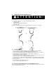
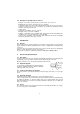
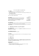
5 Safety Instructions for Hydraulic Hoses ATTENTION! - by no means the hose must be exposed to brake fluid as this fluid will destroy outer layer of hose - do not expose the hose to any of the following aggressive fluids: • acid, lye or solvent • alcohol and fuel • battery and automatic transmission fluid • phosphate ester Clean hose immediately with water and detergent when it was exposed to such fluids. 1 2 3 5 5.
Danger can be caused by: - Uncontrolled hose movement after a hose rupture caused e.g. by external influence. - Emerging of the pressure medium under pressure. - Inflammation of pressure medium near igniting sources Dangers can be prevented by e.g. protective coverings or shieldings 5.2.
5.6 - Examples for possible defects of hoses Damages of the surface and the interior (e.g. chafe marks, cuts or fissures). Embrittlement of the surface (fissuration of the hose material). Deformations, which are not in accordance with the natural shape of the hoses, in pressureless condition or under pressure or in case of bendings, e.g. separation of material layers, blister formation, squeezing or break spots. Leakage points. Instructions for installation were not observed.
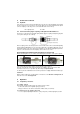
8 Connection of the tool 8.1 Hydraulic Two short hoses (each 0.5 m long) are fitted to the tool; they are connected with the motor pump via a hose pair (5 m / 10 m / 20 m, as is necessary). All hoses are colour marked and have quickconnect couplings so that they can be connected without the risk of mix-up: HP = High pressure 8.
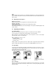
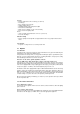
Note: Before working on the motor pump or for coupling/decoupling the hoses, make sure that the motor pump is switched off (electric connection) or disconnected from the mains and that the lines are unpressurized. 9.2 Operating of the star grip 1 Opening of the arms: Rotate star shape ring 1 to the right hand side and hold it in this position. Closing of the arms: Rotate star shape ring 1 to the left hand side and hold it in this position.
Do not reach between the spreader arms! 10.3 Pulling - The chains may only be used for pulling with the rescue device. When pulling using a chain, make sure that bolt and hook are properly accommodated, so that the chain does not slip off.. Use only flawless chain sets. Have an expert check the chains at least once a year. Refer to the separate operating manuals 10.
Spreader • Distance between the arms on the tips (see item 15) • No leakages • Easy operation of the star grip • Handle existing and fast • Identification plate and position plates legible • Protection boot undamaged • Quick connect couplings can be connected easily • Dust covers in the right position Hoses • check according safety instructions for hoses (see item 5) • Check for oil leakage Function testing • Perfect opening and closing with star grip standard version resp. pump-mounted control valves 12.
13.2.3 Change of hydraulic oil - after 200 uses, latest after 2 years, the hydraulic oil has to be changed. - in any case if the oil of the pump (motor / hand pump) which belongs to the unit is changed. By changing the used oil, it should be avoided that the new oil is polluted by the used oil of the rescue tool. Procedure: The rescue tool is in closed (retracted) position • Change of oil has to be effected at the pump.
13.3.5 Labels All damaged or illegible indentification stickers (Safety instructions, type label a.s.o) have to be replaced. Procedure: Remove damaged stickers and clean surface with acetone • Put on new stickers. 13.3.
15 Technical data Type LSP 40 B LSP 40 EN LSP 60 EN LSP 60 F Ref. no. 84150/0890 84150/0895 84150/0547 84150/0560 Spreading force (kN) 40 ... 120 41.5 ... 230 62 ... 230 62 ... 230 in all operating ranges Spreading distance min. (mm) 620 720 800 800 39...58 w. KSV 1145...65 w. KSV 13 Pulling force (kN) 28 ... 61 26 ...
15.1 Peeling Type LSP 40 B LSP 40 EN LSP 60 EN LSP 60 F LSP 80 EN Max. thickness of steel plate t (mm) 4 4 5 5 5 Max. opening (mm x mm) 500 x 500 520 x 520 650 x 650 650 x 650 500 x 500 15.2 Oil recommendations For LUKAS hydraulic devices, use mineral oil in accordance with DIN 51 524 and others Range of oil temperature Viscosity rating A B - 24 ... + 30 °C - 18 ... + 50 °C HL 5 HLP 10 C D - 8 ... + 75 °C + 5 ... + 80 °C HLP 22 HLP 32 E - 8 ...