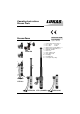
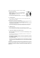
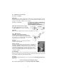
Operating Instructions Rescue Tools 84150/6106-85 GB Issue 04.2006 Rescue Rams replaces 09.2005 10 11 12 1 2 3 4 5 6 7 8 9 10 11 12 LZR 12/550 PS 1 Control valve with star ring 1.1 Hose, black: Pressure Hose, blue: Return Quick-connect socket StMu 61 - 0 Quick-connect plug StNi 61 - D Hydraulic cylinder Piston rod Claw, cylinder side Claw, piston side Peeling tip Penetration tip Counterpart for peeling 9 7 1.1 3 5 6 2 4 8 LZR 12/...
1 Basic operation and designated use of the machine The machine has been built in accordance with state-of-the-art standards and the recognized safety rules. Nevertheless, its use may constitute a risk to life and limb of the user or of third parties, or cause damage to the machine and to other material property. 1.
.3 Before transporting the machine always check that the accessories have been safely stowed away. 3.4 Make sure that there is enough lighting during work. 3.5 Avoid any operation that might be a risk to machine stability. 3.6 Check the machine at least after every operation for obvious damage and defects. Report any changes (incl. changes in the machine’s working behaviour) to the competent organization /person immediately. If necessary, stop the machine immediately and lock it.
• phosphate ester Clean hose immediately with water and detergent when it was exposed to such fluids. 1 2 3 4 5 5.
Dangers can be prevented by e.g. protective coverings or shieldings 5.2.1 Do not go near leaks! - High pressure oil easily punctures skin causing serious injury, gangrene or death! - If injured, seek emergency medical help! Immediate surgery is required to remove oil! - Do not use finger or skin to check for leaks! - Lower load or relieve hydraulic pressure befor loosening finttings! 5.3 - Storage of hoses Hoses are subject to a natural aging even if they are stored correctly.
5.6 - Examples for possible defects of hoses Damages of the surface and the interior (e.g. chafe marks, cuts or fissures). Embrittlement of the surface (fissuration of the hose material). Deformations, which are not in accordance with the natural shape of the hoses, in pressureless condition or under pressure or in case of bendings, e.g. separation of material layers, blister formation, squeezing or break spots. Leakage points. Instructions for installation were not observed.
6.2.3 Type LZR../... One-stage rams for pushing with constant compressive force over the whole stroke. 6.2.4 Type LTR ../... Telescopic rams for pushing with different compressive forces in the piston stages and low collapsed height in comparison with the stroke. 6.2.5 Type LZR 12/550 PS One-stage ram with supplementary operating possibilities (patented) - for pushing, as 6.2.3 - for piercing an opening (steel up to a thickness of 6mm) when using the penetration tip at the piston rod.
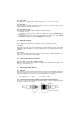
Before coupling, remove the dust protection covers and unlock the connect socket with adjusting ring by turning it. Withdraw the sleeve and connect plug and socket while holding the sleeve in this position. Release the sleeve and set the showglass to „red“ with the adjusting ring. Now the parts are connected and locked. Decoupling is done in the reverse order.
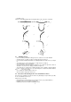
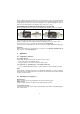
8.3 Principles on rescue rams 8.3.1 LZR../... und LTR./.. Important! When applaying the tool make sure that all tips of both the body - mounted and the piston - mounted claw have a firm and safe grip with the load so as to avoid any point load. Lifted loads have to be supported by suitable cribbings or other packings. 8.3.2 Use of extensions According to the regulations of DIN 14751 T3, and DIN EN 13204 (draft 6.98) a use of extensions is not allowed.
9 Dismantling of the device / Stop after operation 9.1 Rescue ram 9.2 Hydraulic Power Package After each use retract the piston rod until it protrudes only a few mm. This hydraulically and mechanically relaxes the device. As soon as the rescue work is finished, the power package must be switched off, and the hoses must be disconnected from the ram. Remark: While being stored, the piston of the ram might advance slightly due to changes of the ambient temperature.
Should the tool have been equipped with couplers of different brand which do not have this safety function, overpressure would be released through another safety valve (adjusted to approx. 30 MPa) included with the control valve block. In this case oil spill would be observed in the star grip area. As soon as sufficient pressure is released the valve becomes tight again. Should further constant leakage ocur, please have the tool inspected by LUKAS personnel.
11.3.2 Set of identification stickers All damaged or illegible indentification stickers (Safety instructions, type label a.s.o) have to be replaced. Procedure: Remove damaged stickers and clean surface with acetone • Put on new stickers. 11.3.3 Quick couplers Quick couplers on the 0,5m hoses have to be replaced when - external damage can be observed, - the locking sleeve doesn´work any more, - oil spill occurs even when the coupling is properly connected.
Technical data Type LZR12/300EN LZR12/500EN LZR12/700EN LZR12/550PS LZR19/325 Ref. no. 84150/6101 84150/6102 84150/6103 84150/6088 84150/6092 Compressive force (kN) 120 190 (in all operating ranges) Piston stroke (mm) 300 500 700 550 325 Length retracted (mm) 450 680 900 800 460 Length extended (mm) 750 1180 1600 1350 785 Dimensions wxh (mm) 171 x 82 192 x 82 100 x 200 Weight (incl. oil filling) (kg) 13.0 18.0 24.0 21.8 14.
13.1 Peeling with LZR 12/550PS max. thickness of steel (mm) max. opening (mm x mm) 6 550 x 550 13.2 Oil recommendations For LUKAS hydraulic devices, use mineral oil in accordance with DIN 51 524 and others Range of oil temperature Viscosity rating A B - 24 ... + 30 °C - 18 ... + 50 °C HL 5 HLP 10 C D - 8 ... + 75 °C + 5 ... + 80 °C HLP 22 HLP 32 E - 8 ... + 70 °C HF - E 15 Remarks biodegradable Recommended viscosity range: 10 ... 200 mm²/s, delivered with HLP 22 to DIN 51 524 13.