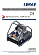
Operating instructions for rescue equipment Hydraulic power unit P 630 SG 175070085 EN Edition 11.
Content Page 1. Danger classi¿cations 5 2. Product safety 6 3. Proper use 10 4. Power unit designation 11 5. Functional description 11 5.1 5.2 5.3 5.4 5.5 5.6 5.7 General information Installation of the power unit Motor Valves Pumps Frame with side sections Connection to the rescue equipment 6. Connecting the hoses / devices 11 12 13 14 15 15 15 16 6.1 Coupling the mono-couplings 16 7. Erection and start-up 18 7.1 Set-up 7.2 Start-up 18 18 8. Operation 20 8.1 8.2 8.3 8.
Content Page 13. Technical data 13.1 13.2 13.3 13.4 13.5 13.6 13.7 13.8 39 Power unit Noise emissions Sparking plug Sparking plug spanner Fuel Engine oil Hydraulic fluid recommendation Operating and storage temperature range 39 41 42 42 42 43 43 43 14. EC Declaration of Conformity 44 15.
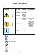
1. Danger classifications We differentiate between various different categories of safety instructions. The table shown below shows you an overview of the assignment of symbols (pictograms) and signal words to the speci¿c danger and the possible consequences.
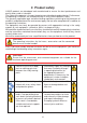
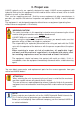
2. Product safety LUKAS products are developed and manufactured to ensure the best performance and quality when used as intended. The safety of the operator is the most important consideration in product design. Furthermore, the operating instructions are intended to help in using LUKAS products safely.
In the event of malfunctions, immediately deactivate the device and secure it. Repair the fault immediately. Do not carry out any changes (additions or conversions) to the equipment without obtaining the approval of LUKAS beforehand. Observe all safety and danger information on the device and in the operating instructions. All safety and danger information on the device must always be complete and in a legible condition.
If you spill any fuel when using combustion engines, you must remove the spilled fuel completely before starting the engine. Keep combustion engines and their fuels away from sources of ignition since otherwise there will be a danger of explosion. Refuelling whilst the engine is running is strictly prohibited! In order to prevent the danger of ¿re, you should ensure adequate ventilation when operating combustion engines and you must keep a safety distance of at least 1m (39.4 in.
The generally applicable, legal and other binding national and international regulations pertaining to the prevention of accidents and protection of the environment apply and are to be implemented in addition to the operating instructions. WARNING/CAUTION! The device is intended exclusively for the purpose stated in the operating instructions (see chapter "Proper Use"). Any other use is not in accordance with its designated use.
3. Proper use LUKAS hydraulic units are specially designed to supply LUKAS rescue equipment with hydraulic Àuid so that this equipment can be used to rescue victims of road, rail or air traf¿c accidents as well as from buildings. Their use for supplying pressure / Àuid to rescue equipment of other manufacturers is possible, yet requires the technical inspection and approval by LUKAS in each individual case.
4. Power unit designation P 630 S G Type group Coding for hydraulic power units Motor variants Valve variants Valve variants: S = Simultaneous operation Motor variants: G = Petrol engine 5. Functional description 5.1 General information In the case of all LUKAS hydraulic power units, the hydraulic pump is operated with a motor. The pump conveys the Àuid from the hydraulic oil tank and builds up the pressure in the tool. Fluid is distributed to the connected equipment through control valves.
5.
5.3 Motor WARNING/CAUTION! See also the separate operating instructions of each engine manufacturer accompanying the delivery. 5.3.1 Petrol engine These hydraulic units are equipped with a combustion engine driven by the fuel "petrol". The power units are equipped with a cable-pull starter with which the engine is started.
5.4 Valves Both valves of the power unit in the pump block are ¿xed in place. The pump block is fully integrated into the hydraulic power unit. The hose assemblies (pressure line (grey) and return (blue)) must be connected to the pump block. The rescue equipment is connected to the hose assemblies. Model P 630 units are equipped with a SIMO connecting block. The connecting block of the P 630 SG also has a TURBO function.
5.5 Pumps The LUKAS hydraulic power units model P 630 are equipped with a SIMO connecting block. The pump is rigidly connected to the connecting block. Double-Àow pump for operating with SIMO valve The pump used always has two pressure stages per pump feed Àow, one low pressure and one high pressure. Low-pressure level (LP) = up to 14 MPa* High-pressure level (HP) = up to 70 MPa* *) 1 MPa = 10 bar) The changeover from low pressure to high pressure is carried out automatically by the pump.
6. Connecting the hoses / devices ATTENTION! When connecting the hose assemblies / units, always ensure that the connection components are not dirty. Clean prior to use if necessary! WARNING/CAUTION! Before connecting the equipment, make sure that all the components used are suitable for the maximum operating pressure of the hydraulic unit! In cases of doubt, you must consult LUKAS directly before connecting the equipment! 6.
Remove the dust caps before coupling together. Then push the male and female parts together and turn the locking sleeve on the female coupling in the direction "1" until the locking sleeve clicks in place. The connection has been made and locked. Decoupling is accomplished by turning the locking sleeve in direction "0". Coupling of the hose assemblies when under pressure is also possible, assuming that the connected equipment is not turned on.
7. Erection and start-up 7.1 Set-up WARNING/CAUTION! Because of possible spark formation, combustion engine units and electrical equipment cannot be used in an explosion-risk area. Units with combustion engines must not be used in enclosed spaces, as there is a danger of poisoning and/or asphyxiation! The unit is to be set up in a suitable location (secure location / Àat surface / suf¿cient distance from vehicles, loads, sources of ignition, etc.). LUKAS units work perfectly at an angle of up to 20°.
4. Now bleed the hydraulic power unit: 5. Set all levers of the distributor valve to circulation at static pressure (see also the chapter "Valves"). Open and remove the tank cap so that air enters the tank. 6. Open the venting plug on the pump block, tilt the power unit backwards by approx. 45° (see illustration) and wait until oil comes out from the bolt. Pump block P 630 SG Venting plug 7. When oil comes out at the venting plug, the air has been removed from the pump.
7.2.3 Commissioning (after the first filling or prior to use) 1. Check the Àuid level of the engine oil, the hydraulic Àuid and the fuel tank. Top up if necessary. For precise reading off of the Àuid levels and for ¿lling, the hydraulic unit should be as level as possible. 2. Now connect the extension hoses and/or hose reels (unless already connected to the unit) and/or couple the rescue equipment. 8.
8.2 Turning the engine off 1. Set the ON / OFF switch to the OFF position. 2. When the engine has come to a standstill, close the fuel tap. For more details on switching off the engine, please refer to the separate operating instructions of the engine manufacturer! CAUTION! Never touch hot engine parts: this could result in severe burns! 8.3 Refuelling The engine must be switched off for refuelling! Procedure: 1. Open the fuel tank cap. 2.
8.4 Controlling the valves ATTENTION! The control levels on the hydraulic power unit should always be switched to the neutral position (de-pressurised) prior to starting the engine in order to prevent unwanted movements of connected hydraulic equipment. 8.4.1 "Simultaneous operation" control valve (SIMO) P 630 SG A switching lever that controls the valves (see the top illustration) is located on the pump block.
9. Dismantling the equipment / deactivation following operation Once the work has been completed, all connected equipment is to be reset to its neutral position (storage position) before the unit is shut down. You can then switch off the engine of the power unit.
10. Tests The hydraulic power units are subject to very high levels of mechanical stress. A visual inspection must therefore be carried out after every use and at least one visual inspection must be carried out every six months. This reveals wear and tear in good time; punctual replacement of these wearing parts prevents damage to the equipment.
10.1.2 Function check Operating time per day Functional test up to 1 hour 1 x annually up to 8 hours 1 x per quarter up to 24 hours 1 x per month In addition to these test intervals you need to carry out a function test if: - the unit makes suspicious noises, - there is a justified suspicion of internal damage to the unit.
11. Maintenance and repair 11.1 General information LUKAS hydraulic units model P 630 require only limited maintenance. For service work, special training is unnecessary; however, knowledge of the function of the power unit, the legal safety instructions and dealing with the required tools are basic prerequisites. ATTENTION! Never use unnecessary force during maintenance work that could damage the components of the power unit or compromise operational safety.
ATTENTION! Since LUKAS hydraulic units are designed for top performance, only those components in the replacement parts lists for the relevant unit can be replaced. Any other components in the unit may only be replaced if: - You have participated in an appropriate LUKAS service training course. - You have the express permission of LUKAS customer service (upon request, we will check for the grant of permission.
Replacing the hydraulic fluid - procedure: 1. Place the power unit on a slightly elevated base so that the drain plug for the hydraulic Àuid can be easily reached. 2. Place a suitable collection container under the "A" drain plug. 3. Open the "B" ¿ller cap, remove the "A" drain plug and let the hydraulic Àuid run into the provided collection container. 4. Screw the "A" drain plug in again (tightening torque max. 5 Nm). B A 5. 6.
11.3 Additional service work NOTE: Non-observance of the maintenance plan can lead to malfunctions that are not covered by the warranty. For dismantling the sparking plug, use a commercially-available sparking plug spanner with universal joint and spanner size of 16 mm (5/8 inch).
11.3.1 Replacing and cleaning the air filter NOTE: Keeping the air ¿lter in good condition is extremely important. Penetrating dirt leads to damage and wear in the engine in case of incorrect installation, incorrect damage or unsuitable ¿lter inserts. Always keep the air ¿lter insert clean. Procedure: If present, remove the rear side panel of the hydraulic power unit, in that the ¿xing clip and the side panel are removed. 1. Unscrew both bolts from the air ¿lter cover and remove the cover. 2.
11.3.2 Replacing, cleaning and setting the sparking plug Procedure: In order to deliver good performance, the sparking plug must have a correct electrode gap and be free from deposits. 1. Detach the sparking plug connector and remove any dirt near the sparking plug. 2. Unscrew the sparking plug using a 16 mm (5/8 inch) sparking plug spanner. 3. Check the sparking plug. Replace the sparking plug if it is damaged, extremely dirty, the sealing washer is in poor condition or the electrodes are worn. 4.
11.3.4 Mono-couplings The mono-couplings must be replaced if: - there is external damage, - the locking does not function, - hydraulic Àuid continues to leak in the coupled/uncoupled state. WARNING/CAUTION! Never repair couplings: they must be replaced by genuine LUKAS parts! Procedure for coupling to valve block: 1. 2. 3. 4. 5. 6. First empty the hydraulic tank as described in the chapter "Replacing the hydraulic Àuid". Remove screwed ¿ttings on the coupling.
ATTENTION! Ensure that connection “T1”/"T2" on the pump block is always connected to connection “T” on the mono-coupling. 4. Position the new coupling and tighten the union nuts on the hose assemblies to a torque of MA = 40 Nm and push the cover of the couplings back. 5. The hydraulic Àuid tank must be re¿lled and the power unit vented. 11.3.
12. Fault analysis Fault Combustion engine will not start NOTE: In case of faults which directly affect the combustion engine, please also observe the separate instructions in the operating instructions of the engine manufacturer.
Fault The motor is running, but the connected rescue equipment is not moving / moving very slowly upon activation of the valve. Check Check hose Cause Hose assembly not connected properly or is damaged Solution Check connection of hose and reconnect if necessary. Check the switch position of the valve lever on the pump block of the hydraulic unit Valve not switched to supply line pressurisation. Switch valve to pressure load of the supply line.
Fault Connected rescue device does not reach its ¿nal position Check Check hydraulic Àuid volume in hydraulic tank Connected rescue device does not reach its speci¿c performance data During function test: Check the details of the rescue A pressure gauge installed between the device rescue equipment and the hydraulic power unit does not indicate the maximum operating pressure of the equipment.
Fault Fluid coming out from hydraulic Àuid tank Check Connected unit not in base position yet and Àuid coming out of ¿ller cap? Cause Return of the hydraulic Àuid from the rescue device exceeds the tank’s maximum quantity when ¿lled.
Fault It is frequently not possible to couple hose assemblies Check Cause Hydraulic Àuid not adapted to the application situation Solution Hydraulic Àuid must be replaced (see chapter "Recommended hydraulic Àuids") Coupling defective Coupling must be replaced immediately Leak in the couplings Coupling defective Coupling must be replaced immediately Leakage at the drive shaft of the hydraulic pump Shaft seal defective.
13. Technical data Because all values are subject to tolerances, there may be small differences between the data for your device and the data in the following tables! The values may also differ because of reading inaccuracies and/or tolerances in the measuring equipment used. NOTE: The following tables contain only the technical data required for standard acceptance. Additional data concerning your unit can be obtained from LUKAS on request. The limitation of the max.
13.1.2 Technical data P 630 SG Device type P 630 SG Article number 81-53-20 Motor type 4-stroke petrol engine Engine power rating [kW] 2.2 [HP] 3.0 [min-1] Engine speed 3000 / 3800 [rpm.] Feed rate simultaneous (HD)1) [l/min] 2 x 0.55 / 2 x 0.7 [gal.-US/min] 2 x 0.15 / 2 x 0.18 Feed rate turbo (HD)1) [l/min] 1 x 1.1 / 1 x 1.35 [gal.-US/min] 1 x 0.29 / 1 x 0.36 Feed rate simultaneous (ND)2) [l/min] Feed rate turbo (ND)2) [l/min] Max. operating pressure (HD)1) [MPa]3) Max.
13.2 Noise emissions (Sound pressure level) Device type P 630 SG Speed 3000 [1/min] / [rpm] 3800 [1/min] / [rpm] Idle run (according to EN) [dB(A)] 80 84 Full load (according to EN) [dB(A)] 84 88 Idle run (according to NFPA) [dB(A)] 73 77 Full load (according to NFPA) [dB(A)] 77 80 Explanation of dual number noise emission values according to DIN EN 13204:2012-09 Serial number of the machine, operating conditions and other characteristic properties: Model ...P 630SG, type ...
13.3 Sparking plug Sparking plug type: CR5HSB (NGK) U16FSR-UB (DENSO) 13.4 Sparking plug spanner Universal joint sparking plug spanner with spanner size 16 mm (5/8 inch) 13.
13.6 Engine oil 13.7 Hydraulic fluid recommendation Mineral oil DIN ISO 6743-4 for LUKAS hydraulic equipment and others Oil temperature range -20 .... +55°C Oil designation HM 10 Viscosity rating VG 10 Remarks A Oil temperature range -4.0 .... +131°F Oil designation HM 10 Viscosity rating VG 10 Remarks A recommended range of viscosity: 10...200 mm²/s Supplied with HM 10 DIN ISO 6743-4. (10…200 cSt.
14.
15.
WARNING/CAUTION! Before connecting the equipment, make sure that all the components used are suitable for the maximum operating pressure of the hydraulic unit! In cases of doubt, you must consult LUKAS directly before connecting the equipment! Please dispose of all packaging materials and removed items properly. LUKAS Hydraulik GmbH A Unit of IDEX Corporation Tel.: (+49) 0 91 31 / 698 - 0 Fax.: (+49) 0 91 31 / 698 - 394 e-mail: lukas.info@idexcorp.com www.lukas.