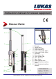
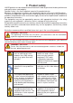
Instruction manual for rescue equipment Rescue Rams alternative coupling system: 6 8 13 14 4 5 3 2 2 1 1 7 7 3 11 11 10 9 12 9 10 12 1 2 3 4 5 6 7 8 9 10 11 12 13 Star grip Control valve Hydraulic cylinder Piston rod (R41x) Piston rod 1 (R42x; R43x) Piston rod 2 (R42x; R43x) Handhold Claw, piston side Claw, cylinder side Hose, pressure Hose, return Mono-coupling male Quick-disconnect coupling (male) 14 Quick-disconnect coupling (female) 174010085 EN Edition 10.2014 replaces 01.
Content Page 1. Hazard classes 4 2. Product safety 5 3. Safety regulations for hydraulic hoses 8 3.1 Advices for hoses 9 3.2 Safeguarding the environment in the event of failure of the hoses 9 3.3 Storage of hoses 9 3.4 Labelling the hoses 10 3.5 Dates for inspections and replacement of hoses 10 3.6 Examples of possible defects of hoses 10 4. Proper use 11 5. Description of the functions 12 5.1 Description 12 5.2 Circuit diagram 12 5.3 Control of the operating movements 12 5.
10. Repairs 21 10.1 General information 21 10.2 Preventative service 22 10.3 Repairs 23 11. Troubleshooting 26 12. Technical Data 29 12.1 Recommended hydraulic fluid 33 12.2 Hoses 33 12.3 Operating and storage temperature ranges 33 13. EC Declarations of conformity 34 14.
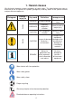
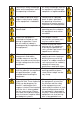
1. Hazard classes We distinguish between various categories of safety notes. The table below gives you an overview of the assignment of symbols (pictograms) and key words to the specific hazard and possible consequences.
2. Product safety LUKAS products are developed and manufactured in order to guarantee the best performance and quality when used properly. Operator safety is the most important aspect of the product design. Moreover, the operating instructions are intended to help the safe use of LUKAS products. The generally applicable, legal and other binding regulations pertaining to the prevention of accidents and protection of the environment apply and are to be implemented in addition to the operating instructions.
Observe all safety and danger notes on the equipment and in the operating instructions. All safety and danger notes on the equipment are to be kept complete in a legible condition. Any mode of operation which impairs safety and/or stability of the equipment is forbidden! Comply with all specified dates or dates specified in the operating instructions pertaining to regular controls / inspections on the equipment.
Ensure adequate lighting when you are working. Before transporting the equipment, always ensure that the accessories are positioned such that they cannot cause an accident. Always keep these operating instructions within reach where the equipment is used.
3. Safety regulations for hydraulic hoses WAR N IN G / C A U TION / AT T E NT I O N! - Never bring the hoses into contact with brake fluid. - The hoses are to be cleaned immediately should they come into contact with the following fluids: • • • • acids, lyes, solvents alcohol, fuel and ATF (Automatic Transmission Fluid) battery acid phosphate ester It is also imperative that the hoses be inspected for damage following cleaning! If necessary, the hose assemblies are to be replaced! 1 2 3 4 6 5 Fig.
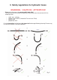
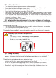
3.1 Advices for hoses - The determined operating pressure may not be exceeded. Tensile load and torsion to the hoses must be avoided (see figure 2, item 1). 1). Do not kink the hoses (see figure 2, item 2). 2). Do not drag or lay hoses across sharp edges (see figure 2, item 3). 3). Do not connect twisted hoses (see figure 2, item 4). 4). Never drive over the hoses with a motorised vehicle. Hoses laid loosely across roads or paths are to be protected from damage e.g.
3.4 Labelling the hoses - The hose is to bear the name of the manufacturer and the authorised operating pressure. - The press sleeve is to bear the maximum authorised operating pressure and the manufacturers identification and month / year of manufacture. month / year operating pressure manufacturers identification 3.
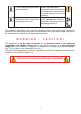
4. Proper use The LUKAS rescue equipment is designed specifically for the emergency services. Their objective is to free people trapped in traffic accidents when the clearance distance of a spreader is insufficient e.g. by spreading or lifting car parts (see figure below). Their objective in other disasters is to rescue buried or trapped persons (e.g. to remove pieces of concrete from collapsed houses). The equipment can also be used under water at a depth of up to 40m (131 ft).
5. Description of the functions 5.1 Description The rescue rams are double-acting hydraulic cylinders. Extension / retraction are carried out hydraulically. The direction of travel is controlled via a valve with star grip. All rescue rams ensure full load-holding function when disconnected from the hydraulic supply (e. g. when being unintentional decoupled; defective hose, and so on). (For reasons of safety, rams R414 are internally safeguarded from 63 MPa = 630bar.
5.4 Type R 41x Type R 41x rescue rams are one-stage cylinders for applying pressure with a constant pressure force along the entire stroke. 5.5 Type R 43x / R 42x Type R 43x / R 42x rescue rams are multi-stage cylinders for applying pressure. Depending on the piston stage, they have varying pressure forces. However, the pressure force remains constant within one piston stage. An advantage offered by this range is the large stroke at a relatively low construction height. 5.
6. Connecting the equipment 6.1 General information There are two short hoses on the side of the equipment: they are connected to the pump unit via two hoses. All hose assemblies are marked with a colour and have couplings to enable unmistakable connection. REMARK: The devices can be equipped with different coupling systems. They differ only by the article number and not by the designation. Of course the coupling systems can also be reequipped at a later time.
REMARK: We recommend coupling the coupling halves in a pressureless state, when working in areas with low ambient temperature and the usage of extension hose assemblies / hose reels, otherwise decoupling could need very high expenditure of force. To protect them from dust, the accompanying dust protection caps must be put back on. WARNING/CAUTION! The mono-couplings may not be screwed off the hose assemblies and / or the hose assemblies be confused! 6.
7. Operation 7.1 Preparatory measures 7.1.1 Commissioning Before commissioning and following repairs, the equipment must be deaerated. - Connect the equipment to the hydraulic pump (see chapter “Connecting the equipment”). - Extend / retract the equipment without any load at least twice (see chapter “Operation of the star grip”). REMARK: We recommend that during the deaeration, the attached aggregate for the hydraulic supply should stand on a higher level than the body of the rescue tool.
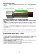
7.1.2 Support Before you can work using the rescue ram, you must ensure adequate support: this includes a necessary substructure. The rescue rams come equipped with a claw on the cylinder side and on the piston side so that they can become hooked (see figure 4).
WARNING / CAUTION! Never use a rescue ram without claw or adequate accessories! The cylinder could slip away while moving and this could result ininjuries of the user. Furthermore the piston rod or the adapter of the claw could be damage thereby. WARNING / CAUTION! When positioning the rescue ram (without LUKAS support bearings), it is imperative that all four ends of both the piston claw and the cylinder claw are flush.
7.3 Operating the star grip (cover: item 1) Extend piston ( ): Turn the star grip in a clockwise direction (in the direction of the relevant symbol) and keep in this position. Retract piston ( ): Turn the star grip in an counterclockwise direction (in the direction of the relevant symbol) and keep in this position. “Dead-man” function: Following release, the star grip automatically returns to the central position, guaranteeing the full load-holding. 7.
8.2 Hydraulic unit Upon completion of work, the unit must be deactivated. 8.3 Hoses First of all, decouple the pressure hose then the return hose as described in chapter “Connecting the equipment”. Ensure that you put the dust protection caps back on to the couplings. 9. Maintenance and service The equipment is subject to very high mechanical stresses. A visual inspection is to be carried out after every use: however, at least one visual inspection is to be carried out annually.
10. Repairs 10.1 General information Servicing may only be carried out by the manufacturer or personnel trained by the manufacturer and by authorised LUKAS dealers. Only LUKAS spare parts may be used to replace all components (see spare parts list) since special tools, assembly advice, safety aspects, inspections might have to complied with (see also chapter “Maintenance and Service”).
10.2 Preventative service 10.2.1 Care regulations The exterior of the equipment is to be cleaned from time to time in order to protect it from external corrosion. Oil is to be applied to the metallic surfaces. 10.2.2 Function and load test If there is any doubt regarding the safety or reliability of the equipment, a function and load test must also be performed. LUKAS offers appropriate test equipment to this end. 10.2.
10.3 Repairs 10.3.1 Changing or tightening hoses Hoses of the pressure and/or return pipe leaks or hoses are defective. Tighten the hoses on the safety valve. (Please note! Observe torque of MA = 40 Nm!) REMARK when using mono-couplings: If you want to change the hoses, you have to dismantle the mono-couplings. CAUTION (by usage of mono-coupling-system)! Take care that the port ‘T’ of the rescue cylinder is always connected to the port ‘T’ of the mono-coupling.
10.3.2 Mono-couplings The mono-couplings on the connection hoses of the equipment must be replaced in the event of: - external visible damage, - the locking device not working, - hydraulic fluid continually leaking in a coupled/uncoupled state. WARNING / CAUTION! Never repair couplings: they are to be replaced by original LUKAS parts! During assembly, tighten the connection nut of the hose assembly with a torque of MA = 40 Nm. Procedure: 1. Remove the cover from the couplings. 2.
10.3.3 Quick-disconnect-couplings The quick-disconnect-couplings on the connection hoses on the equipment must be replaced in the event of: - external visible damage, - the locking device not working, - hydraulic fluid continually leaking in a coupled/uncoupled state. WARNING / CAUTION! Never repair couplings: they are to be replaced by original LUKAS parts! During assembly, tighten the connection nut of the hose assembly with a torque of MA = 35 Nm. Procedure: 1.
11. Troubleshooting Trouble Control Cause Cylinder piston Are the hoses moves slowly or connected jerkily when activated properly? Does the pump unit work? Have you checked Equipment doesn’t come up with the full the hydraulic fluid power.
Trouble Control Cause Solution Hydraulic fluid leak on the piston rod Defective rod seal Repair by an authorised dealer, by Damage to the personnel specially piston trained by LUKAS, or by LUKAS itself Secure the loads and Leak on the handhold Increase load? Load increase move them by using (e.g.
Trouble Control with mono-couplingsystem: Leak in the couplings with quickdisconnect-couplingsystem: Leak in the couplings Cause Solution Is the coupling damaged? coupling damaged Coupling must be replaced immediately Is the coupling damaged? coupling damaged Coupling must be replaced immediately Is the leak only Safety valve on the coupling reacted male (in uncoupled status)? After pressure release there is no more leakage.
12. Technical Data Since all values are subject to tolerances, minor differences may occur between the data on your equipment and the data in the following schedules! Type R 420 Pressure force (piston 2) Pressure force (piston 3) R 424 R 430 81-40-30 81-40-32 81-40-34 81-40-40 (174040000) (174050000) (174060000) (174070000) Ref. No. Pressure force (piston 1) R 422 [kN] 269 269 [lbf.] 60474 60474 [kN] 134 134 [lbf.] 30124 30124 [kN] - 39 [lbf.] - 8800 max.
Type R 410 Piston stroke Length (retracted) Length (extended) Dimensions wxh [kN] 137 124 [lbf.] 30799 27876 [mm] 300 500 700 [in.] 11.8 19.7 27.6 [mm] 450 680 900 [in.] 17.7 26.8 35.4 [mm] 750 1180 1600 [in.] 29.5 46.5 63.0 [mm] 95 x 174 [in.] 3.74 x 6.85 Weight including hydraulic fluid filling [kg] 13,1 17,8 24,3 [lbs.] 28.9 39.2 53.6 max. operating pressure [psi.] min. needed volume of hydraulic fluid [Mpa] * 70 10000 [l] ** 0,5 0,8 1,2 [gal.US] 0.
Type Ref. No. R 420 R 422 R 424 R 430 114070000 114040000 114060000 114050000 [kN] 269 269 [lbf.] 60474 60474 Pressure force (piston 2) [kN] 134 134 [lbf.] 30124 30124 Pressure force (piston 3) [kN] - 39 [lbf.] - 8800 max. stroke (piston 1) [mm] 295 365 445 295 [in.] 11.6 14.4 17.5 11.6 [mm] 280 340 430 280 [in.] 11.0 13.4 16.9 11.0 Pressure force (piston 1) max. stroke (piston 2) max. stroke (piston 3) [mm] - 245 [in.] - 9.
Type Ref. No. R 410 R 412 R 414 114110000 114120000 114130000 [kN] Pressure force (in all operating ranges) [lbf.] Piston stroke Length (retracted) Length (extended) Dimensions wxh 27876 300 500 700 11.8 19.7 27.6 [mm] 450 680 900 [in.] 17.7 26.8 35.4 [mm] 750 1180 1600 [in.] 29.5 46.5 63.0 [mm] 95 x 174 [in.] 3.74 x 6.85 13,1 17,8 24,3 28.9 39.2 53.6 [Mpa] * 70 [psi.] 10000 0,5 0.13 coupling system * ** 30799 [in.] min.
12.1 Recommended hydraulic fluid Mineral oil DIN ISO 6743-4 for LUKAS hydraulic equipment and others A A Oil temperature range Oil code Viscosity rating -20 .... +55°C HM 10 VG 10 Oil temperature range Oil code Viscosity rating HM 10 VG 10 -4.0 .... +131°F recommended viscosity range: 10...200 mm²/s Remarks Remarks (10…200 cSt.) Supplied with HM 10 DIN ISO 6743-4.
13.
14.
Please dispose all packaging materials and dismantled parts properly LUKAS Hydraulik GmbH A Unit of IDEX Corporation Tel.: (+49) 0 91 31 / 698 - 0 Fax.: (+49) 0 91 31 / 698 - 394 e-mail: lukas.info@idexcorp.com www.lukas.com Made in GERMANY rescue_rams_manual_174010085_en.