
Manual


13
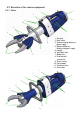
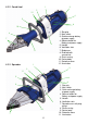
4.2.4 Rescue ram
1 Star grip
2 Main switch
3 Quick exchange battery
or power supply
4 Release button for
Battery and power supply
5 Ventilation slots
6 Cylinder piston
7 Plastic casing
8 Device body
9 Top claw
10 Bottom claw
11 Illumination
6
9
2
1
5
4
3
10
7
8
11
11
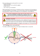
4.3 Hydraulic circuit diagram
To enable comprehension of the function, a simplifi ed hydraulic cylinder of the rescue
equipment (A) + hand valve (B) are depicted here.
A
B
cut / close / pulling /
squeezing
spreading /
opening
or extend piston
or retract piston
NOTE:
When working with the eDRAULIC rescue ram, it should be applied to the object
to be processed in such a way that the battery or power supply can be replaced
at any time.