Instruction manual for rescue equipment Spreaders 171010085 EN Edition 11.2014 replaces 01.
Content Page 1. Hazard classes 4 2. Product safety 5 3. Proper use 8 4. Description of the functions 9 4.1 Description 9 4.2 Unit in detail 10 4.3 Circuit diagram 11 4.4 Control of the operating movements 11 4.5 Hydraulic supply 11 4.6 Hoses 11 5. Connecting the equipment 12 5.1 General information 12 5.2 Coupling the mono-couplings 12 5.3 Coupling the quick-disconnect-couplings 14 6. Operation 15 6.1 Preparatory measures 15 6.2 Operating the star grip 15 7.
12. Technical data 37 12.1 Peeling 42 12.2 Recommended hydraulic fluid 42 12.3 Operating and storage temperature ranges 42 13. EC Declaration of conformity 43 14.
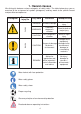
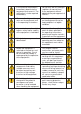
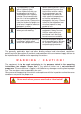
1. Hazard classes We distinguish between various categories of safety notes. The table below gives you an overview of the assignment of symbols (pictograms) and key words to the specific hazard and possible consequences.
2. Product safety LUKAS products are developed and manufactured in order to guarantee the best performance and quality when used properly. Operator safety is the most important aspect of the product design. Moreover, the operating instructions are intended to help the safe use of LUKAS products. The generally applicable, legal and other binding regulations pertaining to the prevention of accidents and protection of the environment apply and are to be implemented in addition to the operating instructions.
In the event of malfunctions, immediately deactivate the equipment and secure it. The malfunction is to be repaired immediately. Do not carry out any changes (additions or conversions) to the equipment without obtaining the prior approval of LUKAS. Observe all safety and danger notes on the equipment and in the operating instructions. All safety and danger notes on the equipment are to be kept complete in a legible condition.
The equipment is filled with a hydraulic fluid. These hydraulic fluids can be dangerous to health if swallowed or their vapours inhaled. Direct contact with the skin is to be avoided for the same reason. Please also note that hydraulic liquids can also have a negative effect on biological systems. Ensure adequate lighting when you are working.
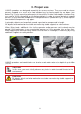
3. Proper use LUKAS spreaders are designed especially for rescue services. They are used to release persons trapped as a result of a road accident e.g. by forcing open the car doors (see below Fig. 1) or by squashing other parts of the vehicle. In other catastrophic situations they are used to lift (by spreading) or to displace objects in order to rescue buried or trapped persons, e.g. by concrete components in collapsed houses (see below Fig. 2), and to squash constructional components, e.g. pipes.
WARNING / CAUTION! The following may not be squeezed: - live cables - hardened parts such as springs, spring steels, steering columns and rollers - explosive bodies such as airbag cartouches NEVER operate the rescue equipment at a higher operating pressure than that stated in the chapter “Technical data”. A higher setting can result in material damage and/or injuries.
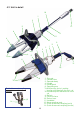
4.2 Unit in detail 10 1 3 5 12 6 9 11 8 2 9 2 4 1 11 3 6 8 7a 5 6 12 10 6 7b Quick-disconnect coupling system: 13 14 10 1 Star grip 2 Control valve 3 Spreader body 4 Handle 5 Hand guard 6 Spreading arm 7a Multifunction tip incl.
4.3 Circuit diagram To enable comprehension of the function, a simplified hydraulic cylinder of the rescue equipment (A) + hand valve (B) are depicted here. spreading A pulling / squeezing B 4.4 Control of the operating movements The spreading arms movement is controlled via the star grip of the mounted valve. (see cover, item 1 and, below, figure 3). fig. 3 star grip 4.5 Hydraulic supply A LUKAS motor pump or hand pump only may be used to drive the equipment.
5. Connecting the equipment 5.1 General information There are two short hoses on the side of the equipment: they are connected to the pump unit via two hoses. All hose assemblies are marked with a colour and have couplings to enable unmistakable connection. REMARK: The devices can be equipped with different coupling systems. They differ only by the article number and not by the designation. Of course the coupling systems can also be reequipped at a later time.
Before coupling, remove dust protection caps, then connect male and female, and turn the locking sleeve of the female to direction „1“ until the locking sleeve locks into place. The connection is now in place and secure. Decoupling is by turning the locking sleeve to direction „0“. The equipment can also be coupled under pressure provided the connected equipment is not activated.
5.3 Coupling the quick-disconnect-couplings The equipment is connected to the hydraulic pump via quick-disconnect-coupling halves (male and female). X Y Before coupling unlock the connect socket by turning the sleeve into position X. Retract sleeve and connect plug and socket. Release sleeve and turn it into position Y. Now the connection has been made and locked. Uncoupling is done in the reverse order.
6. Operation 6.1 Preparatory measures 6.1.1 Commissioning Before commissioning and following repairs, the equipment must be deaerated. - Connect the equipment to the hydraulic pump (see chapter “Connecting the equipment”). - Open / close the spreader arms of the equipment without any load at least twice (see chapter “Operation of the star grip”). REMARK: We recommend that during the deaeration, the attached aggregate for the hydraulic supply should stand on a higher level than the body of the rescue tool.
7. Spreading, pulling, peeling and squeezing 7.1 Safety notes Before rescue works can commence, the position of the obstacle must be stabilised. You must ensure an adequate substructure and / or adequate support of the object. World-wide, safety guidelines pertaining to the specific country are to be observed and complied with.
spreading spreading Working surface is too small, tips slip off. Only for increasing the size of a gap (not suitable for spreading) Tips get a safe grip. 17 Increasing a gap Increasing a gap Work with the tips only. Do not damage the arms.
7.3 Pulling - LUKAS chain sets are to be used for pulling purposes. - Before the pulling process can be performed, ensure that the bolt and hook fit correctly to prevent the chain from slipping. - Only chain sets in perfect condition may be used. - The pull chains are to be inspected at least once per year by an expert. - See separate operating instructions for the relevant chain set! Mounting bore for chain set SP 310 / SP 510 SP 512 Mounting bore for chain set SP 300 7.
7.5 Squeezing Basically, squeezing may only be carried in the area of the tips, unless an additional squeezing device is used – see figures 6 and 7 below. (This additional squeezing device is only available as an accessory for the spreader SP 310). fig. 6 fig. 7 A Squeezing plates A B C Use of this squeezing device enables squeezing closer to the spreader arm pivot point, resulting in a higher squeezing force. Spreader arm Assembly: 1.
8. Dismantling the equipment / deactivation following operation 8.1 Spreader Once work has been completed, the spreader arms are to be closed so that there is a tip distance of just a few mm. This relieves the hydraulic and mechanical strain on the equipment. 8.2 Hydraulic unit Upon completion of work, the unit must be deactivated. 8.3 Hoses First of all, decouple the pressure hose then the return hose as described in chapter “Connecting the equipment”.
9.1 Spreader, overall Inspections to be carried out: Visual inspection Spreader • Opening width of the spreader arms on the tips (see chapter “Technical data”), • General tightness (leaks), • Operability of the star grip, • Existence and stability of handle, • Labels completely existent and legibly, • Covers in perfect condition, • Couplings must be easy to couple, • Dust protection caps must be available.
10. Repairs 10.1 General information Servicing may only be carried out by the manufacturer or personnel trained by the manufacturer and by authorised LUKAS dealers. Only LUKAS spare parts may be used to replace all components (see spare parts list) since special tools, assembly advice, safety aspects, inspections might have to complied with (see also chapter “Maintenance and Service”).
10.2 Preventative service 10.2.1 Care regulations The exterior of the equipment is to be cleaned from time to time in order to protect it from external corrosion. Oil is to be applied to the metallic surfaces. 10.2.2 Function and load test If there is any doubt regarding the safety or reliability of the equipment, a function and load test must also be performed. LUKAS offers appropriate test equipment to this end. 10.2.
10.3 Repairs 10.3.1 Chaging the tip (SP 510 and SP 512) Procedure: 1. Use the pulling pin to remove the roll pin “A”, 2. Replace tip, CAUTION! Before assembly, apply LUKAS special grease to all sliding surfaces after having thoroughly cleaned them. 3. Hammer in new roll pin. CAUTION! Before assembly, apply LUKAS special grease to all sliding surfaces after having thoroughly cleaned them.
10.3.2 Replacing the plug-on tips (SP 300 / SP 310) Procedure: 1. In order to remove the plug-on tips “G”, you need to push the buttons “J” on both sides of a spreader arm completely and simultaneously and then remove the plug-on tip from the spreader arm by pulling it forwards. 2. Place the new tips onto the arm until they automatically click in place on the spreader arm. J H H J G G NOTE: Always replace both plug-on tips.
10.3.3 Changing or tightening hoses Hoses of the pressure and/or return pipe leaks or hoses are defective. Tighten the hoses on the safety valve. (Please note! Observe torque of MA = 40 Nm!) REMARK when using mono-couplings: If you want to change the hoses, you have to dismantle the mono-couplings. CAUTION (by usage of mono-coupling-system)! Take care that the port ‘T’ of the rescue tool is always connected to the port ‘T’ of the mono-coupling.
10.3.4 Spreader arm, spreader tips, protection cover and handle replacement (SP 510 and SP 512) Components to be replaced Required work steps Handle 1. - 3. and 7. Protective cover 1. - 4. and 7. Plug-on tips 1. - 5. and 7. Lever links 1. - 5. and 7. Spreader arms 1. - 6. and 7. Procedure: 1. Close the rescue unit until a gap of only a few mm remains between the tips. Disconnect the device from the hydraulic power supply unit and clean thoroughly. C B 2.
J H J F 5. Drive the pins “F” out with a drift and remove the plug-on tips “G”. Remove the locking rings “H” and remove the handlebars “J”. J G H L K L 6. The pins “L” can be removed after removing the locking rings “K”. You can now remove the spreader arms “M” and replace them. M K M 7. The work steps must be carried out in reverse order to fit the new parts. CAUTION! Don’t forget to apply LUKAS special grease to all sliding surfaces.
10.3.5 Spreader arm, spreader tips, protective cover and handle replacement on the SP 300 spreader Components to be replaced Required work steps Handle 1., 2. and 8. Protective cover 1., 5. and 8. Plug-on tips 1. - 4. and 8. Lever links 1. - 4., 6. and 8. Spreader arms 1. - 6. and 8. Work steps: 1. Close the rescue unit until a gap of only a few mm remains between the tips. Disconnect it from the hydraulic power supply unit and clean thoroughly. A 2.
C C 3. Remove the screws “C“ and “D”. D C E C 4. Remove the two two-piece locking elements “E” on the protective cover “F” and remove the two-piece protective cover by pulling it sideways.
5. H In order to remove the plug-on tips “G”, you need to push the buttons “J” on both sides of a spreader arm completely and simultaneously and then remove the plug-on tip from the spreader arm to the front. J H J G G 6. You need to remove the locking rings “K” and the lever links “L” to replace the spreader arms “H”.
7. Also remove the locking rings “M” and remove the pins “N”. You can then remove the spreader arms “H”. H M N H M 8. The work steps must be carried out in reverse order to fit the new parts. CAUTION! Don’t forget to apply LUKAS special grease to all sliding surfaces. NOTE: The torque required can be taken from the spare parts list of your particular unit.
10.3.6 Mono-couplings The mono-couplings must be replaced in the event of: - external visible damage, - the locking device not working, - hydraulic fluid continually leaking in a coupled/uncoupled state. WARNING / CAUTION! Never repair couplings: they are to be replaced by original LUKAS parts! During assembly, tighten the connection nut of the hose assembly with a torque of MA = 40 Nm. Procedure: 1. Remove the cover from the couplings. 2.
10.3.7 Quick-disconnect-couplings The quick-disconnect-couplings must be replaced in the event of: - external visible damage, - the locking device not working, - hydraulic fluid continually leaking in a coupled/uncoupled state. WARNING / CAUTION! Never repair couplings: they are to be replaced by original LUKAS parts! During assembly, tighten the connection nut of the hose assembly with a torque of MA = 35 Nm. Procedure: 1. Loosen the connection nut of the hose assembly and remove the coupling. 2.
11.
Trouble Control Cause Damages on the surface of the hydraulic hoses Mechanical damages or contact with aggressive agents Defective rod seal Damage to the piston Hydraulic fluid leaks on the piston rod Solution Replace hoses Repair by an authorised dealer, by personnel specially trained by LUKAS, or by LUKAS itself Secure the loads and Leak on the handhold Increase load? Load increase move them by using (e.g.
Trouble Control Cause Especially by usage check the hose connection of mono-couplings: connections of the to the couplings Leak on the handhold hoses interchanged Returnline disabled Solution reconnect the hoses to the coupling in the right way disconnect the returnline from the coupling, clean it and reconnect it.
type SP 300 81-10-15 (111051000/171051000) ref. no. min. spreading force (25mm / 0.98in. from the tips) [kN] 36 [lbf.] 8090 [kN] 125 [lbf.] 28100 spreading force HSF (according to NFPA) [kN] 40 [lbf.] 9000 spreading force LSF (according to NFPA) [kN] 33 max. spreading force max. spreading distance [lbf.] 7419 [mm] 605 [in.] 23.8 max. pulling force (on mounting borehole for chain set) [kN] 31 [lbf.] 7000 pulling distance (on mounting borehole for chain set) [mm] 475 [in.
type SP 310 81-10-25 (111010000/171010000) ref. no. min. spreading force (25mm / 0.98in. from the tips) max. spreading force spreading force HSF (according to NFPA) spreading force LSF (according to NFPA) max. spreading distance [kN] 46 [lbf.] 10300 [kN] 308 [lbf.] 69200 [kN] 55 [lbf.] 12400 [kN] 44 [lbf.] 9890 [mm] 720 [in.] 28.3 max. pulling force (on mounting [kN] borehole for chain set) [lbf.] 41 9200 [mm] 573 [in.] 22.6 pulling force HPF (according to NFPA) [kN] 32 [lbf.
type SP 510 ref. no. min. spreading force (25mm / 0.98in. from the tips) [kN] 62 [lbf.] 13900 max. spreading force (25mm / 0.98in. from the tips) [kN] 230 [lbf.] 51706 [kN] 79,9 [lbf.] 17962 [kN] 54,6 [lbf.] 12275 spreading force HSF (according to NFPA) spreading force LSF (according to NFPA) max. spreading distance max. pulling force (on mounting borehole for chain set) pulling distance (on mounting borehole for chain set) [mm] 800 [in.] 31.50 [kN] 55 [lbf.
type SP 512 ref. no. min. spreading force (25mm / 0.98in. from the tips) [kN] 84 [lbf.] 18900 max. spreading force (25mm / 0.98in. from the tips) [kN] 120 [lbf.] 26977 [kN] 108 [lbf.] 24279 [kN] 77 [lbf.] 17310 spreading force HSF (according to NFPA) spreading force LSF (according to NFPA) [mm] 610 [in.] 24.0 [kN] 98 [lbf.] 22031 [mm] 437 [in.] 17.2 pulling force HPF (according to NFPA) [kN] 67 [lbf.] 15062 pulling force LPF (according to NFPA) [kN] 49 [lbf.
12.1 Peeling Type SP 310 SP 510 SP 512 max. sheet steel thickness “t” [mm] max. possible peeling length [mm] 520 650 500 [in..] 20.47 25.59 19.69 [in.] 4 5 5 0.16 0.20 0.20 12.2 Recommended hydraulic fluid Hydraulic fluid for LUKAS hydraulic equipment: Mineral oil DIN ISO 6743-4 and others Oil temperature range A -20 .... +55°C -4.0 .... +131°F Oil code Viscosity rating HM 10 VG 10 recommended viscosity range: 10...200 mm²/s Supplied with HM 10 DIN ISO 6743-4.
13.
14.
Please dispose all packaging materials and dismantled parts properly LUKAS Hydraulik GmbH A Unit of IDEX Corporation spreaders_manual_171010085_en.indd subject to revision Weinstraße 39, D-91058 Erlangen Tel.: (+49) 0 91 31 / 698 - 0 Fax.: (+49) 0 91 31 / 698 - 394 e-mail: lukas.info@idexcorp.com www.lukas.