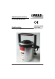
Operating Instructions Rerailing Equipment 84072/0000-85N GB Issue 1.2005 Double-acting Telescopic Cylinders replaces issue 9.
Contents 1 2 3 4 5 6 7 8 9 10 11 12 13 14 15 Page Safety instructions 3 Organizational measures 3 General safety instructions 4 Instructions for maintenance and service 5 Function of individual components 5 5.1 General 5.2 Coupling connectors 5.3 Hoses between control desk and cylinders 5.4 Quick-connect couplers 5.4.1 Hose pair acc. to 84072/1765 5.4.2 Single hose, red 5.4.3 Connection of quick couplers Initial Commissioning 7 Installation 7 7.1 Safety notes 7.1.
1 Safety instructions Basic operation and designated use of the machine 1.1 The cylinders described below may only be used in combination with components from LUKAS rerailing equipment. It is possible to operate them with devices from other manufacturers -- however, this requires technical testing/approval by LUKAS in each individual case. 1.2 The machine is intended exclusively for driving and controlling rerailing equipments. Any other use, e.g.
2.6 Spare parts must comply with the technical requirements specified by the manufacturer. Spare parts from original equipment manufacturers can be relied to do so. It is only allowed to use original LUKAS spare parts or LUKAS system components. 2.7 Replace hydraulic hoses within stipulated and appropriate intervals even if no safety-relevant defects have been detected. This has to be done after 10 years at the latest. 2.
3.11 Working under loads is not allowed if they are only lifted by hydraulic cylinders. If the work is indispensable sufficient mechanical supports are needed additionally. 3.12 Make sure that hoses are not mechanically stressed (pulling, bending etc.). 3.13 When working in the vicinity of live components and cables, it must be ensured that precautions are taken to avoid current conductions or high-voltage flashing over to the motor pump. 3.
5.2 Coupling connectors Apart from the coupling connectors, these cylinder models are also provided with two connector blocks with a safety valve, thus preventing damage to the cylinder in the event of external loads. If pressure exceeds the maximum permissible value, the safety valve will open automatically, and oil will squirt out (protected). 5.3 Hoses between control desk and cylinders Those are normally connected via 10 m long hose pairs (red/blue, ref. 84072/1765).
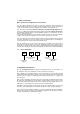
Note regarding the modified release mechanism as of June 2004 When connecting the hoses, be aware of the following basic functions of the quick couplers: X Y Before coupling unlock the connect socket by turning the sleeve into position X. Retract sleeve and connect plug and socket. Release sleeve and turn it into position Y. Now the connection has been made and locked. Uncoupling is done in the reverse order. Connection of the hoses is possible only, when they are depressurized.
7.1.3 Note on retracting the cylinder The load may only be lowered with the pump running. Otherwise a vacuum could be created which would cause air to enter the hydraulic system. 8 Hydraulic connection and operation 8.1 General Prior to connecting the hoses carry out correct cylinder installation as per chapter 7. Make sure that the pump is switched off! 8.1.1 Connecting the telescopic cylinders As described in chapter 5.3, first connect the blue hose, then the red hose of the pair of hoses. 8.
.2.2 Installation / Operation of stacking sets - Lift the load with the cylinder using the normal piston guard plate. - Place the first stacking ring (item 7) centrally on the cylinder body by means of the forked lever. Caution under load! - Lower the load onto this stacking ring and retract the piston. - Remove the standard piston guard plate from the cylinder. Caution under load! (refer to chapter 7.1.1,). - Place the first piston plate (item 8) centrally onto the piston body (using a forked lever).
11.2 - Hydraulic system leakage Check devices for oil loss and replace defective seals if necessary. Important: Carry out the following procedures over an oilpan; dispose of used oil! 11.3 Cylinder components To remove the oil remaining in the piston main zone and piston ring zone, unscrew both couplings from the connecting blocks if necessary and wait until all of the oil drains. Then flush and fill up fresh hydraulic oil. Screw couplings in and tighten them to 45 Nm torque. Vent cylinders acc.
If the faults cannot be rectified, notify an authorized LUKAS dealer or LUKAS Customer Service direct at the following address: LUKAS Hydraulik GmbH, Weinstraße 39, 91058 Erlangen, Germany; P.O. Box 25 60, 91013 Erlangen, Germany; Customer Service tel.: +49 (0) 91 31/69 83 48; fax +49 (0) 91 31/69 83 53.
15 Technical data Order no. Permissible load Length, extended Total stroke Stroke piston 1/2/3 Lifting force piston 1 / 2 / 3 Required oil capacity Ambient temperature Dimensions dia. x height Weight Order no Permissible load Length, extended Total stroke Stroke piston 1/2 Lifting force piston 1 / 2 Required oil capacity Ambient temperature Dimensions dia. x height Weight HP10/T280R 84072/4665N 493 278 90 / 94 / 94 mm 650 / 301 / 104 kN 1.
© Copyright 2002 LUKAS Hydraulik GmbH LUKAS Hydraulik GmbH A Unit of IDEX Corporation Weinstraße 39, 91058 Erlangen • Germany Postfach 2560, 91013 Erlangen • Germany Telefon: +49(0)9131/698-0 • Telefax: +49(0)9131/698-394 e-mail: info@lukas.de Tel_Zyl_LAA_Ag105_e.