Operating instructions Hand Pumps ZPH and HM 84120300085 GB Edition 11.2010 replaces 11.
Contents Page 1. Danger classes 4 2. Product safety 4 3. Proper use 7 4. Main components of the hand pump 8 5. Functional description 8 6. Connection options for hydraulic equipment 9 6.1 Connecting nipples 9 6.2 Quick-disconnect couplings 10 6.3 Monocouplings 11 7. Commissioning 12 7.1 Locking the pump 12 7.2 Bleeding the pump 12 8. Operation 13 8.1 Operation 13 8.2 Shut-down / Storage 14 9. Transport 14 10. Maintenance and repair 14 10.1 Basic requirements 14 10.
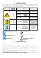
1. Danger classes We distinguish between various categories of safety instructions. The table shown below shows you the overview, via the assignment of symbols (pictograms) and signal words, of the concrete danger and the possible consequences.
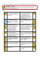
We also recommend that you get instructed by a qualified trainer in the use of the product. WARNING / CAUTION! The operating instructions for the hoses, the accessories and the connected devices must also be heeded! Even if you have already received instruction, you should read the following safety instructions again. Make sure that no body parts or clothing get between the openly visible moving parts of the device.
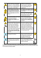
Before switching on/engaging the device or while operating the device, it must be ensured that no one is endangered by the operation of the device. Observe all intervals that are prescribed or specified in the operating instructions for recurring tests and/or inspections. When working in the vicinity of live components and lines, take appropriate measures for preventing current transfers or high voltage flashovers to the device. For repairs only original LUKAS accessories and spare parts are to be used.
WAR N IN G / C A U TION / AT T E NT I O N! The device is specified exclusively for the purpose represented in the operating instructions (see Chapter "Proper use"). Any use that differs or goes beyond this is considered improper. The manufacturer/supplier shall not be held liable for damages resulting from improper use. The risk shall be borne solely by the user. Proper use also includes heeding the operating instructions and complying with the inspection and maintenance requirements.
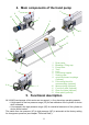
4. Main components of the hand pump 5 9 5 10 1 3 11 12 1 5 13 6 2 7 4 1 5 8 1 1 2 3 4 5 6 7 8 9 10 11 12 13 Drain valve Bleeding / Filling cap Pump lever Tank Lock Connecting nipples Sealing caps quick-disconnect couplings (optional) Connecting block for monocoupling (optional) Monocoupling (optional) Front foot plate (optional) Rear foot plate (optional) Base plate (optional) 5. Functional description All LUKAS hand pumps of this series are two-speed, i.e.
A pressure connection "P" and a return connection "T" with a G1/4“ thread are available for connecting directly to the pump. To connect equipment, appropriate connectors (connecting nipples, quick-disconnect couplings or monocouplings) must be attached. On some of the LUKAS hand pumps offered, one of these connection options is supplied with the pump and is already fitted. Obviously, the connection options fitted can be replaced by others.
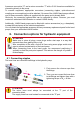
6.2 Quick-disconnect couplings The hose lines are connected via quick-disconnect coupling halves (female and male) to the hydraulic pump in such a way that they cannot be reversed. X Y Before connecting the couplings, remove the dust cap, then pull back and hold the locking sleeve of the female coupling (Position X). Push the male and female couplings together and release the locking sleeve. Finally, turn the locking sleeve into Position Y. The connection is then made and secured.
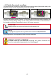
6.3 Monocouplings The hose lines are connected via monocoupling halves (female and male) to the hydraulic pump in such a way that they cannot be reversed. Dust caps Male coupling Female coupling Before coupling, remove dust caps, then connect male and female couplings and turn locking sleeve of the female coupling in direction "1" until the locking sleeve latches. The connection is then made and secured. The decoupling is accomplished by turning the locking sleeve in direction "0".
7. Commissioning NOTE: With the LUKAS hand pump, a little idle stroke may occur when the unit is first used in the high pressure range. However, this idle stroke independently stops after a device is operated 2-3 times. ATTENTION! The hand pump should be as close to horizontal as possible, because otherwise the usable amount changes! The oil fill plug must always be unscrewed one turn before starting operation of the hand pump! This enables the aeration and bleeding of the hydraulic tank.
NOTE: To bleed connected equipment, make sure that the highest point of the connected devices are below the level of the pump. Before operating the pump, you should also open the oil fill screw plug. Only in this way can any trapped air escape the hydraulic system when the pump is operated. You should operate the connected equipment several times without load. When you do this, also follow the separate operating instructions of the connected devices. 8.
8.2 Shut-down / Storage To shut down or store the pump, seal all hydraulic connections with the associated screw plugs or dust caps. After sealing the hydraulic ports, open the drain screw (not up to the stop!) to depressurise the pump. Then carefully clean the external dirt off of the hand pump. In addition, with a longer storage time, the outside of the device should be cleaned and all visible mechanical moving parts need to be oiled.
ATTENTION! Clean the device before checking for dirt! Do not use any aggressive agents for cleaning; it could cause damage to the equipment. Because LUKAS devices are designed for the highest performance, only components may be replaced that are listed in the spare parts lists of the corresponding device. Additional components of the equipment may only be replaced if: - You have participated in a corresponding LUKAS service training course.
Perform an operational check of the hand pump at least once a year; in the case of continuous use, once every half year. Operational check • no suspicious noises, • tests at maximum load. Execution: Place the hand pump on a solid base to operate. Then, connect a test manometer to the supply hose line. Release the pump lever lock and close the discharge valve. Then, the pressurisation to operating pressure corresponding to the specification on the identification plate occurs.
10.5 Repair ATTENTION! Because LUKAS devices are designed for the highest performance, only components may be replaced that are listed in the spare parts lists of the corresponding device and whose replacement is described here. Additional components of the equipment may only be replaced if: - You have participated in a corresponding LUKAS service training course. - You have the express permission of LUKAS customer service (by request, check on the grant of permission.
10.5.2 Foot plate replacement The foot plates must be replaced if external damage is present that represents a danger for user and device upon further use. In particular, the foot plates must be replaced if the stability of the hand pump can no longer be ensured. Procedure: 1. Remove screws A or B. Front foot plate: Rear foot plate: C D A B 2. Remove foot plate C or D and replace it with a new one. 3. Refit the foot plates in the reverse order. 10.5.
Removing the ZPH1/HM1 1l tank: 3. Remove the nut (item E) and sealing ring situated under it (item F). 4. Remove the tank, the seals (item G), the cover (item R) and the filter (item H). On the rescue hand pumps, the intake pipe (item J), the threaded rod (item K), the washer (item L), the O-ring (item M), the serrated washers (items N, O and P) and the bracket (item Q) must also be removed. Pump head J K Tank H P M L O G N Q N G R F E 6. The assembly is done in reverse order.
Removing the ZPH3 tank: 3. Remove the screws (items A and B) and the lock washers under them (items C and D). 4. Remove the tank, the O-rings (items E and F), the serrated washer (item G) and the filter (item H). A C Tank H G E F D B 5. The assembly is done in reverse order. Replace all damaged parts with new ones. The tightening torque for screws "A" is 24 Nm, and for screws "B" is 10 Nm. 10.5.
10.5.4.2 Quick-disconnect couplings The quick-disconnect-couplings should be replaced if: - exterior damage is present, - the lock does not function, - in the coupled and/or decoupled state, hydraulic fluid continuously escapes. Procedure: 1. Unscrew and remove coupling. 2. Screw in new screw-on male coupling and tighten with a torque of MA = 35 Nm. ATTENTION! The return port must always be equipped with a female quick-disconnectcoupling.
11. Troubleshooting Problem Connected device does not move, moves only slowly or moves intermittently. Cause Remedy Fluid level in the hydraulic tank too low Add hydraulic fluid up to max. fill level. Discharge valve open Hose line not properly connected or damaged Close discharge valve. Check connection of the hose line and reconnect it if necessary. Load on the device Use a different device. too high Air in the hydraulic system Bleed system as described in the chapter “Bleeding the pump”.
Problem Cause Remedy Connected device not reaching its limit position Fluid level in the hydraulic tank too low Connected device does not achieve its powerrelated performance data Attention: move the device back into the base position before adding fluid! Usable hydraulic fluid Use a different device with quantity of the pump is a usable quantity below insufficient the maximum usable quantity of the pump. Max.
Problem Cause Remedy In the case of a quickdisconnect coupling system: Leakage on the male coupling Safety valve has responded (in the decoupled state) Male coupling defective After depressurisation, no further leakage occurs. In the case of a quickdisconnect coupling system: Leakage at the female coupling Hydraulic fluid escaping from the hoses or at the joints Damage on the surface of the hydraulic hoses Female coupling defective Female coupling should be replaced immediately.
12. Technical data Because all values are subject to tolerances, there cannot be any differences between the data of your device and the data of the following tables! 12.1 Hand pump data 12.1.1 Pump identification ZPH 1A F / 1 Model series Optional attachments e.g. F = with foot plates (not for HM1) PN500 max. operating pressure in [bar] (1 MPa = 10 bar) rounded usable volume of the hydraulic fluid tank in [l] NOTE: Hand pumps in model series HM1 are generally fitted with a base plate. 12.1.
ZPH3: ZPH 3 (4l Tank) (8l Tank) L B H 12.1.3 [mm] 762 762 [in.] 30 30 [mm] 150 230 [in.] 5.9 9.1 [mm] 231 231 [in.] 9.1 9.1 Fill quantity - Usable quantity Tank size Usable quantity Max. fill quantity (according to pump identification) 1 [l] 4 [l] 5 [l] 8 [l] 12.1.4 1,1 0.29 4,0 1.06 4,5 1.19 8,0 [l] [gal.-US] [l] [gal.-US] [l] [gal.-US] [l] 2.11 [gal.-US] [l] [gal.-US] [l] [gal.-US] [l] [gal.-US] [l] 2.77 [gal.
12.1.6 Change-over pressure LP - HP Pump type Change-over pressure 10 1,450 18 2,611 10 1,450 ZPH 1A ZPH 3 HM 1 12.1.7 [MPa]* [psi.] [MPa]* [psi.] [MPa]* [psi.] *) 1 [MPa] = 10 [bar] Weight Total weight Pump type ZPH 1A ZPH 3 HM 1 = + Weight (Pump head) Weight (Tank) + (Accessories) Weight Weight Tank size Weight (Pump head) (according to pump identification) (Tank) 4,6 10.1 3,7 8.2 4,7 10.4 [kg] [lbs.] [kg] [lbs.] [kg] [lbs.] 1 [l] 4 [l] 5 [l] 8 [l] Accessories Weight 1,28 2.
12.2 Hydraulic fluid recommendation Mineral oil DIN ISO 6743-4 for LUKAS hydraulic equipment and others Oil temperature range -20 .... +55°C Oil code HM 10 Viscosity rating VG 10 Remarks A Oil code HM 10 Viscosity rating VG 10 Remarks A Oil temperature range -4.0 .... +131°F recommended viscosity range: 10...200 mm²/s Supplied with HM 10 DIN ISO 6743-4. (10…200 cSt.
13.
14.
Please properly dispose of all packing materials and removed parts. LUKAS Hydraulik GmbH Phone: (+49) 0 91 31 / 698 - 0 Fax.: (+49) 0 91 31 / 698 - 394 e-mail: lukas.info@idexcorp.com Made in GERMANY ZPH_HM_BA_GB_84120300085_1110.