Operators and Safety Manual Model 644B 10709799 May 1997 ANSI
CONTENTS Section Page No. INTRODUCTION . . . . . . . . . . . . . . . . . . . . . . . . . . . . . . . . . . . . . . . . . . . . . . . . . . . . . . . ii SAFETY. . . . . . . . . . . . . . . . . . . . . . . . . . . . . . . . . . . . . . . . . . . . . . . . . . . . . . . . . . . . . . 1 INSTRUMENTS AND CONTROLS . . . . . . . . . . . . . . . . . . . . . . . . . . . . . . . . . . . . . . . . . 8 BEFORE OPERATING THE MACHINE . . . . . . . . . . . . . . . . . . . . . . . . . . . . . . . . . . . .
INTRODUCTION INTRODUCTION You are about to operate one of the finest forklifts available on the market today. To ensure that your forklift will provide years of safe dependable service, only trained and authorized persons should operate and service the forklift. It is the responsibility of the operator to read, fully understand and follow all operational and safety related instructions contained in this manual. Do not operate the forklift until you have read and fully understand these instructions.
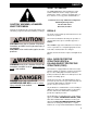
SAFETY SAFETY STANDARD W1038 W CAUTION, WARNING, & DANGER: WHAT THEY MEAN Hazards are identified by the “Safety Alert Symbol” and followed by a signal word: Caution, Warning, or Danger. The ASME/ANSI B56.6 safety standard for rough terrain forklift trucks defines safety requirements relating to the design, operation, and maintenance of these vehicles.
SAFETY REFUELING SAFETY Never smoke near the machine during refueling. Do not permit anyone to be on the machine during refueling. Spilled fuel must be completely absorbed or evaporated before starting the engine. Make sure the fuel cap is in place before starting the engine. Never use an open flame when checking the fuel level in the tank. Never fill the fuel tank with the engine running. Make sure you have adequate ventilation during fueling.
SAFETY OPERATION SAFETY Safe operation is the responsibility of the operator. Improper use of the machine can lead to dangerous situations for yourself, those around you, the machine and the work area. You must have safe working habits and be aware of hazardous working conditions. Thoroughly read and understand this entire manual. Follow all safety rules and practices explained in this manual. The machine must be checked every day or at the start of each shift.
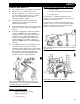
SAFETY Always check clearances under power lines and overhead structures before driving under them. Ensure that correct tire pressure and tire ballast levels are maintained. DO NOT operate the machine near energized power lines. Always contact the electrical power company when operating near power lines. The lines should be moved, insulated, disconnected, or de-energized and grounded before operating in the area. Keep all parts of the machine at least 50 feet away from power lines.
SAFETY Drive carefully and avoid sudden stops and changes of direction. Never place loads that exceed scaffold capacity or subject scaffold to unnecessary “shock” loads. Ensure that the load is stable and secure. Check to see that there are no loose articles that may fall off the fork. Never stack a load on uneven ground. Always check the load charts before picking up a load. Never add unauthorized counterweights. Always be aware of load width.
SAFETY Always pick up the load at its center of gravity. The machine can be levelled side to-side a total of 12.5° in each direction (22% grade). Any slope or grade that exceeds this is considered excessively steep. Avoid parking on slopes. If it is necessary to park on a slope, set the parking brake and block the wheels. When Traveling On Inclines… • Tilt the attachment back and raised only enough to clear the ground. • Avoid turning. If it cannot be avoided, turn slowly and with extreme caution.
SAFETY Additional Safety Instructions: • Maneuver the machine carefully. Do not cause the load to shift or the machine to tip. • Slow down for wet and slippery surfaces and changes in terrain. • Turn the steering wheel smoothly and slow down when turning. • • Do not make sharp turns at high speeds. • Do not continue to operate the machine if an unsafe condition is found. Stop the machine and report the condition to the designated authority.
INSTRUMENTS AND CONTROLS GAUGES INDICATOR LIGHTS 1 3 2 1 240 °F 240 280 115 140 115 140 240 WATER P FUEL °F °C 240 WATER 320 160 60 3/4 1/2 190 160 130 100 F 138 3/4 1/2 190 TRANS P 1/4 E 160 130 100 F FUEL °F °F °C 280 138 320 160 60 TRANS 1/4 E PARK BRAKE PARK BRAKE 80 REAR OSC LOCK BRAKE OIL 60 40 16 80 BATT. REAR OSC LOCK 14 QUARTZ 12 20 0 psi V 00000 10 BRAKE OIL 60 40 16 BATT.
INSTRUMENTS AND CONTROLS IGNITION SWITCH Note: The starter will not engage unless the shift selector is placed in the NEUTRAL position. THROTTLE 1 H1007 Ignition Switch Location H1009 The ignition switch (1) is located on the dash, near the right side. Push throttle pedal (1) down to increase engine speed. BRAKE PEDAL 1 4 Engine Throttle Pedal 2 3 H1021 Ignition Switch Positions The ignition switch has four positions: H1009 (1) OFF: The key may be removed or inserted only at this position.
INSTRUMENTS AND CONTROLS PARK BRAKE CONTROL REVERSE (R): Move the lever fully rearward to select reverse machine movement. Speed Range Selection The transmission has three speed ranges in forward or reverse. To select different transmission speed ranges, rotate the selector handle to the desired position. Speed ranges may be selected while the vehicle is moving in forward or reverse. Note: The transmission requires 3 seconds immediately after engine start for self-diagnostics.
INSTRUMENTS AND CONTROLS Neutral Lock TRANSMISSION DECLUTCH SWITCH F 1 2 3 4 N N 40 R 20 0 psi 1 1 N D TRANSMISSION DECLUTCH H1043 Transmission Declutch Switch H1023 H1023 Neutral Lock The shift selector is equipped with a neutral lock. To lock the shift lever in the NEUTRAL position: 1. Place the lever in the NEUTRAL position 2. Move the neutral lock lever to the (N) NEUTRAL LOCK position. To unlock, move the neutral lock lever to the (D) DRIVE position.
INSTRUMENTS AND CONTROLS Front Wheel Steer Mode 1 2 3 ROUND STEER OBLIQUE STEER FRONT WHEEL STEER STEER MODE SELECTOR V1002 Front Wheel Steer Mode H1044 Steer Mode Selector There are three steer modes available on your machine: Front Wheel Steer mode, also known as “2-Wheel Steer” mode, allows the operator to steer the machine in a conventional manner. The front wheels of the machine steer and the rear wheels remain in position.
INSTRUMENTS AND CONTROLS Oblique Steer Mode V1010 V1003 Step 4 4. Turn the steering wheel to the left about one turn. Oblique Steer Mode Oblique Steer mode, also known as “Crab Steer” mode, enables steering of the front and rear wheels in the same direction. It is generally used to angle the machine in tight areas. Oblique Steer mode moves the machine to the side while moving forward or reverse. 5. Select ROUND steer mode. 6. Turn the steering wheel to the right until it reaches the stop.
INSTRUMENTS AND CONTROLS Joysticks can be moved in any direction and are not limited to front/back, left/right movement. Moving a joystick in a diagonal direction will cause a combination of actions. Front Joystick The front joystick controls transfer carriage extension and attachment tilt. An auxiliary function is also available by pressing the button on top of the handle. See “Auxiliary Joystick Controls” on page 16 for further information. V1013 Step 11 11.
INSTRUMENTS AND CONTROLS Tilting Attachment Down Pushing forward on the front joystick tilts the attachment downwards. Retracting the Transfer Carriage Moving the front joystick to the left retracts the transfer carriage. Rear Joystick The rear joystick controls boom elevation and extension. An auxiliary function is included on the rear joystick. This auxiliary function is reserved for future attachment designs and is not activated on current Model 644B machines.
INSTRUMENTS AND CONTROLS Raising the Boom Pulling back on the rear joystick raises the boom. Retracting the Boom Moving the rear joystick to the left retracts the boom. AUXILIARY JOYSTICK CONTROLS General Description — Auxiliary Joystick Controls Auxiliary Joystick Control Extending the Boom Moving the rear joystick to the right extends the boom. A switch is located on the top of the front joystick, under a protective rubber cap.
INSTRUMENTS AND CONTROLS Tilting Carriage Control Rotating Tilt Carriage to Left Rotating Tilt Carriage to Right Holding the button down and moving the front joystick to the left rotates an optional tilting carriage to the operator’s left. Holding the button down and moving the front joystick to the right rotates an optional tilting carriage to the operator’s right.
INSTRUMENTS AND CONTROLS The control lever (1) is equipped with a safety lock to prevent unintentional operation. Lift the lock ring (2) to unlock the lever and allow it to be moved left or right. Return the control lever to center position and release lock ring to secure lever. FRAME LEVEL INDICATOR 10 5 0 5 The lever can be moved either left or right, tilting the frame accordingly. To level the frame, move the lever in the direction you want the ball in the frame level indicator to move.
BEFORE OPERATING THE MACHINE CHECK THE EQUIPMENT 9 Note: Before you begin your workday, take time to check ( ) your forklift and have all systems in good operational condition. Check the following: 9 9 9 9 9 9 9 9 Warning decals, special instructions and operators manuals. Make sure they are legible and stored in the proper location. NEVER operate without a legible load chart. Engine oil level. Add oil as required. Radiator coolant level. Add coolant as required. Hydraulic fluid level.
BEFORE OPERATING THE MACHINE PLAN YOUR WORK Before you operate, know how and where you will travel, turn and pickup, lift and place loads. An operator must not use drugs or alcohol which can affect his alertness and coordination. An operator on prescription or over-the-counter drugs needs medical approval to safely operate these machines. Choose a smooth level route to prevent possible tipover or loss of load. KNOW THE RULES If possible, avoid crossing… • • • • Ruts. Ditches. Curbs.
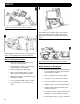
GENERAL OPERATING PROCEDURES STARTING PROCEDURES SHUTDOWN PROCEDURES Before operating, walk completely around the machine. Make certain no one is under it, on it or close to it. Let all other workers and bystanders know you are preparing to start the machine. DO NOT start machine until everyone is clear. Correct shutdown is important to the safe operation of the machine. To start engine... Always follow these steps: 1. Come to a full stop. 2. Set the park brake. 2. Set park brake. 3.
GENERAL OPERATING PROCEDURES FOLLOW SAFE OPERATING PROCEDURES WARNING ALWAYS LEVEL MACHINE BEFORE RAISING BOOM. NEVER TILT FRAME WITH THE BOOM RAISED. MACHINE MAY TIP AND CAUSE SERIOUS PERSONAL INJURY OR DEATH! ALWAYS check the load chart mounted in the machine before lifting a load. Lift only within the capacity of the machine as shown by the load chart. Never tilt the frame when the boom is raised. Operate the controls smoothly–don't jerk the hydraulic controls or steering wheel.
GENERAL OPERATING PROCEDURES LIFT THE LOAD SAFELY WARNING Important: ALWAYS check the load chart mounted in the machine before lifting a load. Lift only within the capacity of the machine as shown by the load chart. 1. If possible, plan to load, unload and turn on flat level ground. If not level, use frame tilt (See “Frame Tilt Control” on page 18) to level machine. Level indicator MUST be centered. Be sure there is enough clearance overhead and all around for lifting and traveling.
GENERAL OPERATING PROCEDURES 4. Level the machine using frame tilt BEFORE the load is raised. (See “Frame Tilt Control” on page 18) DO NOT raise the load for placement if the forks are tilted to one side. If the forklift cannot be positioned so the load is level before lifting, reposition the forklift. The likelihood for forklift tipover is greatly increased if the load is not level before lifting. WARNING ALWAYS LEVEL MACHINE BEFORE RAISING BOOM. NEVER TILT FRAME WITH THE BOOM RAISED.
GENERAL OPERATING PROCEDURES 7. Use the transfer carriage to place the load directly over the landing point. The transfer carriage allows safe and easy placement of the load without moving the machine. (Consult load charts for transfer capacity.) Forks should be level and parallel to the landing surface so that they may be easily retracted from under the load. Before retracting the forks, check landing point for any excessive bowing, cracking noises or other indications of overloading. .
FLUID & LUBRICANT SPECIFICATIONS GENERAL FLUID AND LUBRICANT SPECIFICATIONS General Fluid & Lubricant Specifications System or Component Fuel System1 Fluid or Lubricant Specification See “Fuel Requirements” Hydraulic System Heavy Duty Hydraulic Fluid Amoco Rykon MV or equiv. Engine Cooling System1 Ethylene Glycol/ Pure Water Mix with additives.
FLUID & LUBRICANT SPECIFICATIONS TRANSMISSION OIL SPECIFICATIONS FUEL REQUIREMENTS The following table shows approved lubricants and associated temperature ranges for use with ZF 3WG and 4WG series transmissions. Transmission Oil Selection Chart ZF 3WG-100 & 4WG-100 Transmissions General Diesel fuels are blended to meet the local temperature requirements. The standard grades are: 1. 1D for temperatures -22 to +86 °F (-30 to +30 °C). 2. 2D for temperatures +14 to +122 °F (-10 to +50 °C) Min. Oil Min.
SERVICE/LUBRICATION SCHEDULE MODEL 644B-37 23 22 24 22 23 22 24 22 9 7 22 24 22 19 6 23 19 19 12 25 8 22 24 15 22 23 21 10 12 15 R1014 11 16 28 16 20 16 14 17 16 28 20 13 26 8 25 18 27 28 26 4 26 5 13 3 27 26 21 1 2 18 R1015
SERVICE/LUBRICATION SCHEDULE MODEL 644B-37 SYSTEM CAPACITIES AND PRESSURES HYDRAULIC SYSTEM & RESERVOIR 65 GALS PLANETARY HUB (EACH) FUEL TANK 40 GALS ACCUMULATOR (NITROGEN PRECHARGE) 62 OZ (SEE NOTE 1) 400–425 PSI COOLING SYSTEM 18 QTS TIRES — 13.00 X 24 PER TIRE ENGINE CRANKCASE — JOHN DEERE 14 QTS PRESSURE TRANSMISSION — DRAIN/REFILL (APPROX.
SERVICE/LUBRICATION SCHEDULE MODEL 644B-42 23 22 24 22 23 22 24 22 9 7 22 24 22 19 6 23 19 19 12 25 8 22 24 15 28 22 23 12 21 11 10 15 R1020 16 28 16 20 16 14 17 16 20 13 26 8 25 18 27 26 4 26 5 13 3 27 21 1 2 18 26 R1021 30
SERVICE/LUBRICATION SCHEDULE MODEL 644B-42 SYSTEM CAPACITIES AND PRESSURES HYDRAULIC SYSTEM & RESERVOIR 65 GALS PLANETARY HUB (EACH) FUEL TANK 40 GALS ACCUMULATOR (NITROGEN PRECHARGE) 62 OZ (SEE NOTE 1) 400–425 PSI COOLING SYSTEM 18 QTS TIRES — 13.00 X 24 ENGINE CRANKCASE — JOHN DEERE 14 QTS PRESSURE PER TIRE TRANSMISSION — DRAIN/REFILL (APPROX.
SAMPLE LOAD CHART MAXIMUM BOOM LOAD CAPACITIES AT 24" LOAD CENTER, FOR LIFT AND REACH POSITIONS IN POUNDS AND FEET WITH METRIC CONVERSIONS. TRANSACTION 80" (203 CM) 12 40 MANUFACTURER'S RECOMMENDED CAPACITIES ARE IN CONFORMANCE WITH ANSI/ASME B56.6 STABILITY TESTS USING STANDARD HOMOGENEOUS CUBES 4' × 4' × 4'. INDICATES REAR 11 OSCILLATION LOCK 35 MANUFACTURER'S RECOMMENDED LOADS AND ANGLES SHOWN ARE AT THE HORIZONTAL CENTER OF GRAVITY OF THE ABOVE CUBE.
GENERAL OPERATING PROCEDURES - SUPPLEMENT DRIVE LOCKOUT OVERRIDE Important: Read and understand the following instructions BEFORE using the optional Drive Lockout Override System! Theory of Normal Operation This machine is equipped with a stabilization system that does several things to increase lateral (side-toside) stability. When the boom is raised above 20° elevation: • The transmission is limited to first and second gears. • The rear oscillation lock cylinder is limited to slow (orificed) movement.
GENERAL OPERATING PROCEDURES - SUPPLEMENT Operation of the Drive Lockout Override System To operate the Drive Lockout Override System: WARNING WARNING Failure to follow the instructions in this supplement and the owner/operator manual may result in serious personal injury or death! Note: These procedures only apply to situations where the boom is above 40° elevation. 1. Plan your route of travel. The surface must be firm and as level as possible. Always avoid rough or steep areas. 2.
JLG Industries, Inc. TRANSFER OF OWNERSHIP To: JLG, Gradall, Lull and Sky Trak product owner: If you now own, but ARE NOT the original purchaser of the product covered by this manual, we would like to know who you are. For the purpose of receiving safety-related bulletins, it is very important to keep JLG Industries, Inc. updated with the current ownership of all JLG products. JLG maintains owner information for each JLG product and uses this information in cases where owner notification is necessary.
Corporate Office JLG Industries, Inc. 1 JLG Drive McConnellsburg PA. 17233-9533 USA Phone: (717) 485-5161 Fax: (717) 485-6417 JLG Worldwide Locations JLG Industries (Australia) P.O. Box 5119 11 Bolwarra Road Port Macquarie N.S.W.