
Service Manual User guide
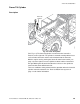


Table Of Contents
- 10709790_B_644B,6K,844C,8K,1044C,10K_Lull_Service_Mnl
- Quick Reference
- Revision Record
- Table Of Contents
- List Of Figures
- List Of Tables
- Section 1 Safety
- Section 2 Identification & Specifications
- Section 3 General Maintenance
- Section 4 Reference Diagrams
- Section 5 Supply, Pressure & Return Hydraulics
- Section 6 Boom & Transfer
- Section 7 Frame Tilt & Oscillation
- Section 8 Transmission
- Section 9 Brakes
- Section 10 Outriggers

Frame Tilt and Oscillation
Service Manual — Models 644B, 6K, 844C, 8K, 1044C, 10K
7-17
Installation, Counterbalance Valve
1. Lubricate O-rings with clean hydraulic oil.
2. Install each cartridge in manifold block and torque to 30–35 ft-lbs.
Frame Level Indicator
Description
Fig. 7-10: Frame Level Indicator
(Ref. Fig. 7-10) The Frame Level Indicator shows the lateral (side-to-side)
angle of the frame relative to level ground. Indicator range is from 0° to 10°
left or right, in increments of one degree. When the ball is centered (0°),
the machine is laterally level. The frame tilt feature may be used to correct
machine angles up to 12.5° to the left or right. See “Frame Tilt Control
Valve” on page 7-3.
Adjustment
Fig. 7-11: Leveling the Frame
0
5
10
5
10
H1004
K1026
Carpenter’s Level