Service Manual Models 644E-42 944E-42 644E-42 - S/N 17569 thru 20123 and 0160002514 & After 944E-42 - S/N 17569 thru 20123 and 0160002514 thru 0160041827 8990461 Revised January 17, 2012 An Oshkosh Corporation Company
EFFECTIVITY PAGE June 2004 - C - Revised Manual January 17, 2012 - D - Revised covers.
SECTION CONTENTS Section Subject Section 1 Safety Practices . . . . . . . . . . . . . . . . . . . . . . . . . . . . . . . . . . . . . . . . . . . . . . . . . . . . . . . 1.1 1.2 1.3 1.4 1.5 1.6 1.7 1.8 Page 1.1 Introduction . . . . . . . . . . . . . . . . . . . . . . . . . . . . . . . . . . . . . . . . . . . . . . . . . . . . . . . . . . Owners/Operators Manual . . . . . . . . . . . . . . . . . . . . . . . . . . . . . . . . . . . . . . . . . . . . . . . Training Mechanics as Operators. . . . . . . . .
Section Subject Page Section 5 Axles, Drive Shafts, Wheels, Tires and Brakes . . . . . . . . . . . . . . . . . . . . . . . . . . . . . . . 5.1 5.2 5.3 5.4 5.5 5.6 5.1 Axle, Drive Shaft and Wheel Component Terminology . . . . . . . . . . . . . . . . . . . . . . . . . General Information . . . . . . . . . . . . . . . . . . . . . . . . . . . . . . . . . . . . . . . . . . . . . . . . . . . . Axle Assemblies . . . . . . . . . . . . . . . . . . . . . . . . . . . . . . . . . . . . . . . . . . . . . . . . . .
Section Subject Section 8 Hydraulic System . . . . . . . . . . . . . . . . . . . . . . . . . . . . . . . . . . . . . . . . . . . . . . . . . . . . . . 8.1 8.2 8.3 8.4 8.5 8.6 8.7 8.8 8.9 8.10 8.11 8.12 8.13 8.14 Page 8.1 Hydraulic Component Terminology . . . . . . . . . . . . . . . . . . . . . . . . . . . . . . . . . . . . . . . . Safety Information . . . . . . . . . . . . . . . . . . . . . . . . . . . . . . . . . . . . . . . . . . . . . . . . . . . . . Specifications . . . . . . . . . . . . . . . . .
Section Subject Page Section 10 Stabil-TRAK™ System . . . . . . . . . . . . . . . . . . . . . . . . . . . . . . . . . . . . . . . . . . . . . . . . . . 10.1 10.2 10.3 10.4 10.1 Stabil-TRAK™ System Component Terminology . . . . . . . . . . . . . . . . . . . . . . . . . . . . . . Stabil-TRAK™ Description. . . . . . . . . . . . . . . . . . . . . . . . . . . . . . . . . . . . . . . . . . . . . . . Stabil-TRAK™ Operation . . . . . . . . . . . . . . . . . . . . . . . . . . . . . . . . . . . . . . . . . . . .
Section 1 Safety Practices Contents PARAGRAPH 1.1 1.2 1.3 1.4 1.5 1.6 1.7 1.8 TITLE Introduction . . . . . . . . . . . . . . . . . . . . . . . . . . . . . . . . . . . . . . . . . . . . . . . . . . . . . . . Owners/Operators Manual . . . . . . . . . . . . . . . . . . . . . . . . . . . . . . . . . . . . . . . . . . . Training Mechanics as Operators . . . . . . . . . . . . . . . . . . . . . . . . . . . . . . . . . . . . . Safety Information . . . . . . . . . . . . . . . . . . . . . . . . . . . . . . . . .
Safety Practices 1.1 INTRODUCTION JLG Industries, Inc. (hereafter, JLG) actively promotes safe practices in the use and maintenance of its products through training programs, instructional manuals and the pro-active efforts of all employees involved in engineering, design, manufacture, marketing and service. This manual is designed to provide service technicians with complete information on the maintenance and repair of the Lull 644E-42 and 944E-42 Telescopic Material Handler.
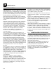
Safety Practices 1.4 The following information provides general safety instructions, including examples of hazard statements with signal words, notification of hazards, methods to help avoid hazards and the consequences of failing to follow the safety information. To avoid possible death or injury, carefully read and follow all safety messages. Fully understand the potential causes of death or injury. 1 MU0920 1.
Safety Practices 1.4.2 Hazard Statements 1.5 Signal words and messages are used in conjunction with the safety alert symbol to create hazard statements. These hazard statements convey important information about safety. ACCIDENT PREVENTION TAG USAGE Four types of hazard statements are used in this manual. Each statement indicates the existence and degree of relative risk of the hazard described within the statement that follows the signal word.
Safety Practices 1.6 SAFETY INSTRUCTIONS Following are general safety statements to consider before performing maintenance procedures on a vehicle. Additional statements related to specific tasks and procedures are located throughout this manual and are listed prior to any work instructions to provide safety information before the hazard occurs. For all safety messages, carefully read, understand and follow the instructions before proceeding. 1.6.
Safety Practices 1.6.3 General Hazards SOLVENTS: Only use approved solvents, and solvents that are known to be safe for use. HOUSEKEEPING: Keep the work area and operator’s cab clean and remove all hazards (debris, oil, tools, etc.). FIRST AID: Immediately clean, dress and report all injuries (cuts, abrasions, burns, etc.), no matter how minor. Know the location of a first-aid kit, and know how to use it.
Safety Practices 1.8 HAZARD/EMERGENCY INFORMATION SIGNS If a replacement sign is needed, refer to the Owners/ Operators Manual and parts catalog for the latest parts numbers and ordering information. Or, contact the JLG Parts Department directly at: Locations of vehicle hazard and other emergency information signs are shown below. As part of routine maintenance, check that ALL hazard and emergency information signs on the vehicle are present and readable. Keep all signs clean.
Safety Practices This Page Intentionally Left Blank 1.8 Model 644E-42/944E-42 Rev.
Section 2 General Information, Specifications and Maintenance Contents PARAGRAPH 2.1 2.2 2.3 2.4 2.5 TITLE 644E-42 / 944E-42 Component Terminology. . . . . . . . . . . . . . . . . . . . . . . . . . . . . Introduction . . . . . . . . . . . . . . . . . . . . . . . . . . . . . . . . . . . . . . . . . . . . . . . . . . . . . . . 2.2.1 Service Methods . . . . . . . . . . . . . . . . . . . . . . . . . . . . . . . . . . . . . . . . . . . . 2.2.2 The Owners/Operators Manual. . . . . . . . . . . . . . . . . . .
General Information, Specifications and Maintenance 2.6 2.7 2.8 2.9 2.10 2.11 2.12 2.2 Fluids, Lubricants and Capacities . . . . . . . . . . . . . . . . . . . . . . . . . . . . . . . . . . . . . 2.6.1 Axles (Differential Housings) . . . . . . . . . . . . . . . . . . . . . . . . . . . . . . . . . . . 2.6.2 Wheel Ends. . . . . . . . . . . . . . . . . . . . . . . . . . . . . . . . . . . . . . . . . . . . . . . . 2.6.3 Lubrication Points (Grease Fittings) . . . . . . . . . . . . . . . . . . . . . . . . . .
General Information, Specifications and Maintenance 2.1 644E-42 / 944E-42 COMPONENT TERMINOLOGY To understand the safety, operation and maintenance information presented in this manual, it is necessary that the operator/mechanic be familiar with the name and location of the major assemblies on this vehicle. The following illustration identifies the components that are referred to throughout this manual.
General Information, Specifications and Maintenance 2.2 2.2.1 INTRODUCTION Service Methods Appropriate service methods and proper repair procedures are essential for safe, reliable operation of this vehicle and the safety of the individual doing the work. This Service Manual provides general direction for accomplishing service and repair work with tested, effective techniques. Following them will assure reliability. 2.2.
General Information, Specifications and Maintenance 2.3 2.3.1 TORQUES SAE Flat Face O-Ring Seal Hydraulic Fittings a. Assembly Procedure Improper assembly of this type of joint will result in leaking joints. Under tightening will result in the joint loosening during normal usage. Foreign material on either seal surfaces will cause damage to one or both mating parts when the joint is tightened resulting in a leaking joint. The absences of the fitting o-ring will cause the joint to leak.
General Information, Specifications and Maintenance c. Adjustable (Angle) O-Ring Boss Fittings To O-Ring Boss Ports Improper assembly of this joint will result in a leaking joint. Failure to position the locknut properly will result in damage to the o-ring. Under tightening of the fitting will result in the fitting loosening during normal operation and the joint leaking. Damaging the o-ring during assembly will result in immediate joint leakage. 1.
General Information, Specifications and Maintenance 2.4 METRIC CONVERSION FACTORS 2.4.1 Approximate American to Metric Conversions When this is known Multiply by To Find TORQUE (moment of force) AIR PRESSURE Pounds per square inch (psi) 6.895 Kilopascals (kPa) HYDRAULIC PRESSURE Pounds per square inch (psi) 0.069 Bar 1.356 Newton meters (Nm) TEMPERATURE (exact) Pound-inches (lb-in) 0.113 Newton meters (Nm) To determine degrees Celsius (° C), subtract 32, then multiply by 0.
General Information, Specifications and Maintenance VOLUME Milliliters (ml) 0,03 Fluid ounces (fl oz) Milliliters (ml) 0,06 Cubic inches (in3) Liters (l) 2,1 Pints (pt) Liters (l) 1,06 Quarts (qt) Liters (l) 0,26 Gallons (gal) (m3) 35 Cubic feet (ft3) Cubic meters (m3) 1,3 Cubic yards (yd3) 0,145 Pounds per square inch (psi) Cubic meters AIR PRESSURE Kilopascals (kPa) HYDRAULIC PRESSURE Bar 14,5 Pounds per square inch (psi) TEMPERATURE (exact) To determine degrees Fahrenheit (° F
General Information, Specifications and Maintenance This Page Intentionally Left Blank Model 644E-42/944E-42 Rev. 6/04 2.
General Information, Specifications and Maintenance 2.5 SPECIFICATIONS 2.5.1 Vehicle Dimensions With Standard Tires: 13.00-24 (644E-42), 15.50-25 (944E-42) Description 644E-42 944E-42 (A) Length (without Forks and TC Rearward) 253" (6.426 mm) 253" (6.426 mm) (B) TransAction Distance 80" (2.032 mm) 80" (2.032 mm) (C) Width 98" (2.489 mm) 101" (2.565 mm) (D) Height (Boom Lowered) 95.5" (2.426 mm) 95.5" (2.426 mm) (E) Wheelbase 131" (3.327 mm) 131" (3.327 mm) (F) Tread Center 84" (2.
General Information, Specifications and Maintenance P Z J O AA K R TC R etra cte d TC Ex ten de d Q U 0.0 B V D G L X L N T W Y A M S 24.0" C E F H Model 644E-42/944E-42 Rev. 6/04 I MU5820 2.
General Information, Specifications and Maintenance 2.5.2 Vehicle Weights - 644E-42 Curb Weight (Vehicle curb weight is figured with 48” carriage, two 48” pallet forks, 12%-full fuel tank and standard tires [no hydrofill]): Open Cab: 24,267 lb (11.007 kg) Closed Cab: 24,708 lb (11.207 kg) Operating Load 6,000 lb (2.721 kg) 2.5.
General Information, Specifications and Maintenance 2.5.
General Information, Specifications and Maintenance 2.5.5 Performance Specifications Note: Performance criteria is based on full throttle engine speed unless otherwise specified or not applicable. Travel Speed (Standard Tires, No Load) 644E-42 944E-42 First Gear 0 - 3.5 mph (0-5,6 km/hr) 0 - 3.5 mph (0-5,6 km/hr) Second Gear 0 - 6.0 mph (0-9,7 km/hr) 0 - 6.
General Information, Specifications and Maintenance 2.5.
General Information, Specifications and Maintenance Fuses - Standard Blade Style: 644E-42 944E-42 F25 - Lights Main (Option) 40 amps 40 amps F26 - Condenser Fan (Option) 25 amps 25 amps F27 - Open — — F28 - Open — — E1 - Transmission Control 12 volt 12 volt E2 - Ignition 12 volt 12 volt E3 - Neutral Start 12 volt 12 volt E4 - Back-Up Alarm 12 volt 12 volt E5 - Stability Brake (644E-42 SN 0160003877 944E-42 SN 0160003881 & Before) 12 volt 12 volt — — E6 - Stability Lock 12 v
General Information, Specifications and Maintenance 2.5.8 Engine Performance Specifications - 644E-42 Note: Engine manufacturer's maximum “high idle” setting is lockwired and sealed. DO NOT disturb this setting. Description Engine Make/Model (SN 20118 & Before, 0160002519 thru 0160003689) Cummins Turbo/4BT3.
General Information, Specifications and Maintenance 2.5.9 Engine Performance Specifications - 944E-42 Note: Engine manufacturer's maximum “high idle” setting is lockwired and sealed. DO NOT disturb this setting. Description Engine Make/Model Cummins Turbo/QSB 4.
General Information, Specifications and Maintenance 2.5.10 Fluid and Lubricant Capacities Fluid & Lubricant Description 644E-42 and 944E-42 Engine Crankcase Oil: Capacity with Filter Change 10.5 qt (10 liters) Filter Capacity 0.85 qt (0,80 liters) Oil Type SAE 15W40 Diesel Engine Oil. (Refer to Section 2.6.5, “Engine.”) Fuel Tank: Total Capacity 50.2 gal (190 liters) Usable Capacity 45 gal (171 liters) Type of Fuel Above 32° F (0° C) Standard No. 2 Diesel. (Refer to Section 2.6.5, “Engine.
General Information, Specifications and Maintenance Hydraulic System: 644E-42 and 944E-42 System Capacity 50.2 gal (190 liters) Reservoir Capacity 33.5 gal (127 liters) Type of Oil ISO Grade 46 Anti-Wear Hydraulic Oil Refer to Section 2.6.4, “Hydraulic System.” 2.5.
General Information, Specifications and Maintenance 2.5.12 Tires Description 644E-42 944E-42 Standard Tire Size 13.00 - 24, 12-ply 15.50 - 25, 12-ply Rock Tire Size (Optional) 13.00 - 24, 12 ply 15.
General Information, Specifications and Maintenance 2.5.14 Tamper Proofing A tamper-proof means is in place on the following adjustable components prior to machine shipment. This can either be tamper-proof paint, or a steel tamper-proof cap. DO NOT attempt to defeat, by-pass or alter any tamper-proof device.
General Information, Specifications and Maintenance 2.6 FLUIDS, LUBRICANTS AND CAPACITIES 2.6.1 Axles (Differential Housings) 2.6.2 Wheel Ends a. Wheel-End Lubricants In general, use a Universal Tractor Fluid that meets the following specifications: a. Axle Lubricants Nominal viscosity at 104° F (40° C) .......................55 cSt In general, use a Universal Tractor Fluid that meets the following specifications: Minimum viscosity at 212° F (10° C) .....................9.
General Information, Specifications and Maintenance 2.6.3 Lubrication Points (Grease Fittings) b. Hydraulic System Capacity Lubricants System capacity ................................ 50.2 gal (190 liters) When lubricating any component via the grease fittings, use multi-purpose lithium-based grease with EP additives that meets NLGI Grade 2 specifications. Products known to meet these requirements include: Reservoir capacity............................. 33.5 gal (127 liters) • AMOCO AMOLITH EP2 2.6.
General Information, Specifications and Maintenance b. Engine Capacities 2.6.7 1. Engine Oil Capacity a. Transfer Case Fluid Transfer Case Capacity w/filter change ....................... 10.5 qt (10 liters) Approved Universal Tractor Fluid Filter .................................................. 0.85 qt (0,80 liters) 2. Cooling System Capacity Capacity ............................................ 14.
General Information, Specifications and Maintenance 2.6.8 Drive Shaft Splines IMPORTANT: DO NOT disassemble any of the drive shafts (refer to Section 5, “Axles, Drive Shafts, Wheels, Tires and Brakes,” of this manual for information covering drive shafts and U-joints). To help ensure optimum performance, the drive shaft assemblies are specially balanced as a unit at the factory. When servicing any flange yoke, slip yoke or drive shaft tube, order a complete assembly.
General Information, Specifications and Maintenance 2.6.10 2.6.11 Paint Unless otherwise specified, paint components, as indicated, in the following sections. For general thread-locking purposes, Loctite® products, manufactured by Loctite Corporation, are recommended. Contact: a. Orange Paint Durable, premium Lull orange paint is available in both a convenient 16-ounce (480 ml) spray can for touch-ups, and in a production-sized one gallon (3,8 liters) container for extensive repainting.
General Information, Specifications and Maintenance 2.8 REPLACEMENT ALWAYS use the correct tool when removing or replacing any part or performing any service. Some procedures may require the use of specialized tools. If needed, many of these tools can be obtained through Snap-on® tool distributors. Contact: Snap-on Incorporated P.O. Box 1410 Kenosha, WI 53141-1410 USA Phone: 1-262-656-5200 Internet: http://www.snapon.com Snap-on® is a registered trademark of Snap-on Technologies, Inc. 2.9.
General Information, Specifications and Maintenance 2.10 BEARINGS 2.10.1 Bearing Removal 1. NEVER remove bearings unless absolutely necessary! Always use the recommended puller to reduce the risk of bearing or related component damage. 2. When bearings or bushings are removed, verify that the bearing or bushing is free from discoloration, nicks, scuffing, and signs of overheating. If in doubt, replace the bearing or bushing. 2.10.2 Bearing Cleaning Wear safety glasses.
General Information, Specifications and Maintenance 2.12 2.12.1 AFTER SERVICE STARTUP AND CHECKS After Service Startup Note: Refer to the Owners/Operators Manual for engine cold-start procedures. 1. Check fluid levels. 2. Connect the negative (-) battery cable(s) to the battery or batteries (if it is disconnected). 3. Start and idle engine. Check for leaks from hydraulic components, engine, axles, transmission, brakes and reservoirs or tanks. Check the levels of all fluids and lubricants. 4.
General Information, Specifications and Maintenance After Transmission Service or Replacement 12. Recheck the level of fluid in the transmission with the engine running at idle. 1. Check transmission oil level and fill to level with oil as required. (Refer to Section 2.6.6, “Transmission,” for information on transmission lubricants.) 13. Add oil as necessary to bring the fluid level up to the FULL mark on the transmission dipstick. Install the oil dipstick.
General Information, Specifications and Maintenance This Page Intentionally Left Blank 2.32 Model 644E-42/944E-42 Rev.
Section 3 Boom Contents PARAGRAPH 3.1 3.2 3.3 3.4 3.5 3.6 3.7 TITLE Boom System Component Terminology . . . . . . . . . . . . . . . . . . . . . . . . . . . . . . . . Boom System . . . . . . . . . . . . . . . . . . . . . . . . . . . . . . . . . . . . . . . . . . . . . . . . . . . . . 3.2.1 Boom System Description. . . . . . . . . . . . . . . . . . . . . . . . . . . . . . . . . . . . . 3.2.2 Boom System Operation . . . . . . . . . . . . . . . . . . . . . . . . . . . . . . . . . . . . . .
Boom 3.1 BOOM SYSTEM COMPONENT TERMINOLOGY To understand the safety, operation and maintenance information presented in this section, it is necessary that the operator/mechanic be familiar with the name and location of the major assemblies of the boom system. The following illustration identifies the components that are referred to throughout this section.
Boom WARNING: DO NOT service the vehicle without following all safety precautions as outlined in the “Safety Practices” section of this manual. Failure to follow the safety practices may result in death or serious injury. 3.2 3.2.1 BOOM SYSTEM BOOM ASSEMBLY MAINTENANCE The boom assembly consists of the inner, intermediate and outer booms and supporting hardware. IMPORTANT: Boom replacement must be completed in sequence, one boom section at a time, as described in these instructions.
Boom 3.3.1 Inner Boom Replacement WARNING: Wear protective footwear with reinforced toe caps and slip-resistant soles. Failure to comply can result in foot or other bodily injury from slipping or falling. 4. At the front of the intermediate boom, remove the capscrews (2) and flat washers (3) holding the top and side wear pads (4) and shims (5) to the inside of the intermediate boom. Label the wear pads and shims positions for later replacement. Save the shims, capscrews and washers.
Boom 6. Loosen the extend chain locknut (10), located at the rear of the outer boom (11), half way. The locknut must remain fully engaged on the threads of the extend chain clevis. 13 15 16 10 10 12 11 17 14 MU0180 7. Return to the cab, fasten your seat belt and start the engine. Retract the boom slightly until slack is noticed in the extend chain. Shut the engine OFF. 8. Move the attachment tilt joystick in both directions to relieve any trapped pressure in the attachment tilt system.
Boom WARNING: 11 Hydraulic fluid leaking under pressure can penetrate the skin, cause infection, gangrene, and death or serious personal injury. If injured, see a doctor immediately. 10 12 Relieve all pressure before disconnecting any component, part, line or hose. Slowly loosen parts and allow release of residual pressure before removing any parts or component. 8 7 6 5 WARNING: Wait for the hydraulic fluid to cool before servicing any hydraulic component. Hot hydraulic oil can cause severe burns.
Boom 17. Label, disconnect and plug the attachment tilt hoses (16) at the fittings at the front of the inner boom section. Cap the fittings on the tilt cylinder to prevent dirt and debris from entering the hydraulic system. 18. Label, disconnect and plug the auxiliary hydraulic hoses (17) at the fittings at the front of the inner boom section. Cap the bulkhead fittings on the gooseneck bracket.
Boom 24. Install a lifting eye (1) to the nut on the attachment tilt cylinder (2). Attach suitable overhead lifting device and sling to the lifting eye. Note: The Inner Boom’s center of gravity is at about six feet (2 m) in from the top front of the boom when all attachments are removed. 25. Remove the retaining ring (3) from the upper attachment pin (4), and remove the pin. 28. Remove the capscrews (5), washers (6) and lower wear pads (7) attached to the front of the intermediate boom.
Boom Note: If replacing the inner boom assembly with a new inner boom, the hose guide, retract chain, remaining wear pads and the attachment tilt cylinder should be removed at this time. (944E-42 Only) Remove and mark the position of the top wear pads (15), side wear pads (16), bottom wear pads (17), shims (18), hose clamp mounts (19), washers (20) and capscrews (21). If the inner boom is not to be replaced, proceed to Step 34. 15 31.
Boom 33. Remove the capscrews (1 and 4) and washers (2) and hydraulic hose track (3) from inside the inner boom. b. Inner Boom Installation WARNING: Wear protective footwear with reinforced toe caps and slip-resistant soles. Failure to comply can result in foot or other bodily injury from slipping or falling. WARNING: 3 NEVER lift a heavy object without the help of at least one assistant or a suitable sling and hoist. Failure to comply can result in death or serious personal injury.
Boom 3. Coat the capscrew (8) with Loctite® 242 (blue). At the rear of the inner boom (5), attach the retract chain (6) to the same hole in the anchor link (7) using one capscrew (8), one flat washer (9). Torque capscrew to, 37 - 66 lb-ft (50 - 90 Nm). 9 (944E-42 Only) Replace the rear inner boom top wear pads (13), side wear pads (14), bottom wear pads (15), shims (16), hose clamp mounts (17), washers (18) and capscrews (19) according to their previously marked positions.
Boom Note: The 644E inner boom, without attachments, weighs 1,050 lbs (480 kg). The 944E inner boom, without attachments, weighs 1,250 lbs (565 kg). 8. Coat clevis pin (9) with anti-seize compound. Attach the extend chain yoke (7) to the inner boom (8) with the clevis pin (9) and two retaining rings (10). 5. Use a suitable overhead lifting device and sling to raise the inner boom and begin inserting it into the intermediate boom at the front of the vehicle. 6.
Boom 12. Coat the capscrews (14) with Loctite® 242 (blue). Use a socket wrench and long extension to install the four capscrews (14) (two-upper and two-lower) and four washers (15) securing the cylinder trunnion clamps (16) to the intermediate boom. Torque capscrews (14) to 245 - 274 lb-ft (333 - 372 Nm). 23 20 Note: ALWAYS replace elastic locknuts with new elastic locknuts to help ensure proper fastening. 13. Coat the capscrew (17) with Loctite® 242 (blue).
Boom Note: ALWAYS use new o-rings when servicing the vehicle. 17. Install new o-rings into the fittings. Lubricate o-rings with clean hydraulic oil. 18. Loosely install the female coupler, male nipple and bulkhead fittings to the bulkhead plate inside the gooseneck. 4 19. Remove the plugs and caps from the hoses and fittings and connect the attachment tilt (1) and auxiliary hydraulic (2) hoses to the fittings on the boom tube gooseneck bracket and attachment tilt cylinder.
Boom 25. Working from the rear of the boom, move the attachment tilt and auxiliary hydraulic hoses (10) until there is approximately a 0.5" (12 mm) gap between the Extend/Retract cylinder trunnion (11) and the hoses. 12 10 11 Note: ALWAYS use new o-rings when servicing the vehicle. 27. Install new o-rings into the fittings. Lubricate o-rings with clean hydraulic oil. 28.
Boom 29. If needed, pull the intermediate boom out slightly to align the extend chain yoke (2) with the bracket. Route the extend chain yoke and chains around the sheave (1) on the intermediate boom. Coat the clevis pin (3) with anti-seize compound. Connect the yoke (2) to the anchor bracket on the outer boom with the clevis pin (3). Secure the pin with two retaining rings (4). 4 31. Clean up all debris, hydraulic fluid, etc., in, on, near and around the vehicle. 32.
Boom WARNING: Avoid prolonged engine operation in closed areas without adequate ventilation. Failure to properly ventilate exhaust fumes can result in death or serious personal injury. 35. Install the boom rear cover (12) using four capscrews (13) and flat washers (14). Coat the capscrews with Loctite® 242 (blue). Torque to 21 - 38 lb-ft (29 52 Nm). 13 WARNING: Hydraulic oil leaking under pressure can penetrate the skin and cause severe personal injury.
Boom 3.3.2 3. At the rear of the boom, remove the capscrew (6), sheave pin (7) and sheave (8). Intermediate Boom Replacement WARNING: Wear protective footwear with reinforced toe caps and slip-resistant soles. Failure to comply can result in foot or other bodily injury from slipping or falling. WARNING: 8 NEVER lift a heavy object without the help of at least one assistant or a suitable sling and hoist. Failure to comply can result in death or serious personal injury. a.
Boom Note: If you are replacing the intermediate boom with a new intermediate boom; remove the following parts and save for re-installation. 10. At the front of the boom, remove the capscrew (22), locknut (23), sheave pin (24) and sheave (25). 8. Remove and mark the position of the top wear pads (13), side wear pads (14), bottom wear pads (15), retainer (16), washers (17) and capscrews (18) at the back of the intermediate boom. 13 18 16 22 24 25 17 14 18 23 15 MU1430 16 MU1160 9.
Boom b. Intermediate Boom Installation WARNING: Wear protective footwear with reinforced toe caps and slip-resistant soles. Failure to comply can result in foot or other bodily injury from slipping or falling. WARNING: NEVER lift a heavy object without the help of at least one assistant or a suitable sling and hoist. Failure to comply can result in death or serious personal injury.
Boom 6. At the front of the intermediate boom, coat the sheave pin (15) and bore with anti-seize compound. Coat the capscrew (13) with Loctite® 242 (blue). Install the sheave (16) into place and insert the sheave pin (15), capscrew (13) and locknut (14). Torque capscrew (13) to, 90 - 162 lb-ft (123 - 220 Nm). 13 15 8. Continue installing the intermediate boom until it makes contact with the front of the outer boom. Remove the overhead lifting device and sling. 9.
Boom 3.3.3 4. Remove all clamps (7) securing the attachment tilt (8) and auxiliary hydraulic tubes (9) and rear hydraulic hoses (10) to the outer boom and frame. Label and remove the tubes. Cap hose ends. Outer Boom Replacement WARNING: Wear protective footwear with reinforced toe caps and slip-resistant soles. Failure to comply can result in foot or other bodily injury from slipping or falling.
Boom 7. Use a suitable overhead lifting device and sling to support the outer boom and allow for the detachment of the lift/lower cylinder. 23 8. Use a suitable overhead lifting device and sling attached to the lift/lower cylinder (14). Remove slack from the sling. 22 9. Remove one capscrew (15) and one locknut (16) securing the lift/lower cylinder pin (17) at the outer boom lift/lower cylinder mount boss on the underside of the outer boom. 19 20 10. Carefully extract the lift/lower cylinder pin (17).
Boom Note: If you are replacing the outer boom with a new outer boom, also remove the following items in Step 18. b. Outer Boom Installation WARNING: Wear protective footwear with reinforced toe caps and slip-resistant soles. Failure to comply can result in foot or other bodily injury from slipping or falling. 18. Remove the capscrews (1), spacers (2), washers (3), nut (4) and boom angle indicator (5).
Boom 4. Secure the pivot pin with the clevis pin (9) and a cotter pin (10). 8. Use a suitable overhead lifting device and sling attached to the lift/lower cylinder. Remove slack from the hoist sling, and raise the lift/lower cylinder (17) into its mount boss on the underside of the outer boom. 6 9. Coat the lift/lower cylinder pivot pin (18) and bore hole with anti-seize compound.
Boom 12. As required, install the hydraulic clamps (1) on the outer boom and secure the attachment tilt (2) and auxiliary hydraulic tubes (3) and hoses (4) within the clamps on the boom and frame according to their previously marked positions. Torque clamp capscrews to, 4 - 8 lb-ft (6 - 11 Nm). 15. Insert the inside boom proximity sensor (9) with the inside jam nut (7) closer to the back of the sensor. Replace the jam nut (8) and secure proximity sensor (9) to outer boom.
Boom Note: If you are replacing the outer boom with a new outer boom, also install the following items. 16. At the front of the outer boom, install the socket head locknut (10) and flat washer (11) securing the retract chain (12) to the outer boom (13). Pull the chain to the front of the outer boom. DO NOT twist or kink the retract chain. 13 10 11 12 19. Install the inner boom, Extend/Retract cylinder and extend chain and attaching hardware. (Refer to Section 3.3.1, “Inner Boom Replacement.”) 20.
Boom 3.4 BOOM CHAINS This vehicle uses a single extend chain to extend the boom and a single retract chain to retract the boom. The extend chain is constructed of 1" pitch links with 6 x 6 leaf lacing. The retract chain is constructed of 3/4" pitch links with 6 x 6 leaf lacing. Note: DO NOT attempt to repair a chain. Replace a stretched or damaged chain with a new part. Always replace both the chain and the clevis.
Boom a. Inspection Guidelines Inspect Plates for Edge Wear Expose the extend and retract chains (refer to Section 3.4.1, b. “Expose Extend Chain for Inspection,” or Section 3.4.1, c. “Expose Retract Chain for Inspection,”) and inspect the chains for the following conditions: Check the chain for wear on the link plate edges caused by running back and forth over the sheave. The maximum reduction of material must not exceed 5%.
Boom Turning or Protruding Pins Highly loaded chain, operating with inadequate lubrication, can generate abnormal frictional forces between pin and link plates. When chain is allowed to operate in this condition, a pin or series of pins, can begin to twist out of a chain, resulting in failure. Examine the pin head rivets to determine if the “VEE” flats are still in correct alignment (1). Chain with rotated/ displaced heads (2) or abnormal pin protrusion (3) must be replaced immediately. (Refer to Section 3.
Boom Other Modes of Failure b. Expose Extend Chain for Inspection • Ultimate Strength Failure - These types of failures are caused by overloads far in excess of the design load. Either fractured plates (6) or enlarged holes (7) can occur. If either of these failures occurs, the chain must be replaced immediately. (Refer to Section 3.4.5, “Boom Extend and Retract Chains Removal and Replacement.”) Note: The tight joints inspection must be done with the chain disconnected from the boom. (Refer to Section 3.
Boom c. Expose Retract Chain for Inspection The retract chain must be removed from the boom in order to be visually inspected. This must be done every 1000 hours or whenever the retract chain is removed from the boom. (If removal of the chain is required refer to Section 3.4.5, “Boom Extend and Retract Chains Removal and Replacement.”) 4. At the front underside of the boom, record the amount of threads extending beyond the elastic locknut (5).
Boom 7. Remove the elastic locknut (10) and flat washer (11) holding the retract chain threaded clevis (12) to the mounting tab. Save the flat washer and discard the elastic locknut. 10 11 12 11. DO NOT attempt to repair a chain. Replace a stretched or damaged chain with a new part. Always replace both the chain and the clevis. It is recommended that when any chain is replaced, that all chains and clevis be replaced at the same time. 12. Measure the chain elongation.
Boom 15. Coat the threads of the threaded clevis (1) with multi-purpose grease. Note: Have a second person help with the installation of the retract chain between the intermediate and outer boom assemblies. 16. From the rear of the boom, one person should push the threaded clevis end (1) under the chain sheave and down between the intermediate boom (3) and the outer boom. The person at the front of the boom should pull the clevis using the string or wire (2) attached to the clevis in Step 6.
Boom 3.4.2 Chain Lubrication After inspection and before being returned to service, chains must be lubricated with a quality chain lubricant (“LUBRIPLATE” Chain & Cable Fluid, “LPS3” or equivalent). The lubricant must penetrate the chain joint to prevent wear. Applying lubricant to the external surfaces will prevent rust, but the chains should be articulated to make sure the lubricant penetrates to the working surfaces between the pins and links.
Boom 3.4.4 Boom Chain Tension Adjustment 5 Note: Always perform Section 3.4.3, “Boom Chain Tension Check,” before adjusting the boom chain tension. 1. Park the vehicle on level ground. Place the travel select lever in the (N) NEUTRAL DETENT position, engage the parking brake switch and raise the boom to a horizontal (level) position. retract the boom completely and turn the vehicle OFF. 6 7 2.
Boom 12. Move the extend chain clevis (11) to the next hole toward the rear of the mounting plates. Coat the mounting pin (10) and bore with an anti-seize compound and reinsert the pin through the mounting plates and the clevis. Reassemble the retaining ring (9). 9 10 Note: If the extend chain still cannot be adjusted within the range of 3.00" (76 mm) and 4.00" (102 mm) the clevis can be repositioned into the last hole in the mounting plates on the front of the outer boom. 16.
Boom a. Component/Assembly Verification The inner to intermediate boom separation should be checked when assembling new boom sections or chains, or when the rear retract chain clevis has been moved forward on the anchor plate. Measure the separation between the inner and intermediate boom top plates (1). The distance should be at least 8-1/2" (216 mm) and not greater than 9-1/2" (241 mm) with the boom fully retracted and the chains properly tensioned.
Boom 5. If the extend chain clevis is in the first hole, the locknut is fully loosened on the clevis, and the distance is greater than 9-1/2" (241 mm); the chain is the incorrect size. (Refer to Section 3.4.1, a. “Inspection Guidelines.”) 3.4.5 Boom Extend and Retract Chains Removal and Replacement a. Extend Chains Removal and Replacement 1. Park the vehicle on a hard, level surface. 2. Fully retract the boom and raise the boom to a horizontal position.
Boom 4. At the rear of the inner boom (1), remove one capscrew (2) and washer (3) securing the extend chain (4) to the anchor link (5). Disconnect the retract chain. 14 15 12 16 3 4 2 13 1 MU4860 5 MU0260 Note: The Extend Chain yoke (8) will not fit under the chain sheave. 5. Remove two retaining rings (6) and clevis pin (7) to disconnect the extend chain yoke (8) from the outer boom (9). Lay the chain assembly flat against the inner boom (10). 6 7 8 7.
Boom 11. If needed, pull the boom out slightly to align the extend chain yoke (8) with the sheave (14). Route the extend chain around the sheave (14) on the intermediate boom. Coat the clevis pin (7) and clevis bore hole with anti-seize compound. Connect extend chain yoke (8) to the outer boom anchor bracket (16) with the clevis pin (7). Secure the pin with two retaining rings (6). ® 12. Coat the capscrew (2) with Loctite 242 (blue).
Boom 6. Attach a threaded eye (2) or a flat washer tack welded to a capscrew (3) to the retract chain clevis (1). The outside diameter of the eye or flat washer must be smaller than the diameter of the threads on the clevis. The string or wire will be used to pull the chain back through the boom during the reassembly. 8. Remove two retaining rings (6) and clevis pin (7) to disconnect the retract chain yoke (8) from the rear of the inner boom (9). Lay the chain assembly flat behind the inner boom.
Boom 12. From the rear of the boom, one person should push the threaded clevis end (11) of the retract chain under the chain sheave (10) and down between the intermediate boom and the outer boom. The person at the front of the boom should pull the front clevis (11) using the string or wire attached to the clevis in Step 6. 18. Adjust retract chain tension. (Refer to Section 3.4.4, a. “Component/Assembly Verification.”) 19. Replace the rear cover on the rear of the outer boom.
Boom 3.5 BOOM WEAR PADS 3.5.1 The wear pads (1) on this vehicle, are for the most part, flat rectangular wear pads with metal inserts (2). The bottom rear wear pads (3), of the intermediate boom, are “U” shaped and have a L shaped retainer (4) to keep them in place. 2 1 4 Boom Wear Pad Replacement When replacing a wear pad on the boom, replace both wear pads on that side of the boom; e.g.: replace top front left and top front right wear pads at the same time.
Boom Use shims (8) under the upper rear wear pads as required to maintain a maximum gap of 0.09" (2,3 mm) (9) at the front edge of the top wear pads and maintain a total maximum gap of 0.09" (2,3 mm) on the boom sides. Shims are available in two thicknesses, 0.06'' and 0.13''. 9 b. Intermediate Boom Coat all wear pad capscrews with Loctite 242® (blue) before installation.
Boom c. Outer Boom d. Extend/Retract Cylinder All outer boom pads (1) are mounted on the front of the outer boom. Remove the top wear pads before removing the bottom wear pads. Lower the gooseneck to the ground until the intermediate boom raises up, providing clearance for removing the bottom pads. Fill the grease pockets (2) of the top rear boom wear pads with multipurpose grease. Use Loctite® 242 (blue) on all wear pad capscrews.
Boom 3.6 QUICK ATTACH ASSEMBLY 3.6.2 Connecting to an Attachment This vehicle is equipped with a quick attach system for easy attachment changes. 1. Perform this procedure on a hard level surface. Position the vehicle directly behind the attachment to be mounted. 3.6.1 2. Tilt the quick attach backward. Disconnecting from an Attachment 1. Park the vehicle on a hard, level surface. 2.
Boom 3.6.3 Quick Attach Disassembly 1. Remove one capscrew (1) and elastic locknut (2). Tap out lower attachment tilt cylinder pin (3). 6. Inspect the pin (6) for nicks or surface corrosion. Use fine emery cloth to fix minor nicks or corrosion. If damaged or if it cannot be repaired the pin must be replaced. 7. Carefully pry and unhook the spring (14) from the quick attach lever/latch (13). 1 8. Remove elastic locknut (10) from the capscrew (11). Remove capscrew from tapped hole. 9.
Boom 3.6.4 Quick Attach Installation 29 1. Install the lock pin (17). 2. Assemble the flat washer (18), quick attach lever/ latch (19), spacer (20), and spring (21) to the capscrew (22). Position straight end of spring as shown in illustration. 28 24 30 Note: ALWAYS replace elastic locknuts with new elastic locknuts to help ensure proper fastening. 3. Thread the capscrew (22) through tapped hole until latch is restrained, but free to travel in normal latching position.
Boom 3.6.5 Attachment Tilt Cylinder Removal 1. Remove hydraulic hoses (1) from the attachment tilt cylinder. Cap and label hoses and ports on attachment tilt cylinder. 2 5 1 4 7 6 3 8 MU0270 MU4870 2. Remove quick attach. (Refer to Section 3.6.3, “Quick Attach Disassembly.”) 3. Install a 1/2”-13 lifting eye bolt (2) to the nut on the attachment tilt cylinder (3). Attach suitable overhead lifting device and sling to the lifting eye. 4.
Boom 3.7 TROUBLESHOOTING This section provides an easy reference guide covering the most common problems that occur during operation of the boom. Boom Troubleshooting Problem 1. Boom will not extend or retract. 2. Auxiliary hydraulics will not operate. Model 644E-42/944E-42 Rev. 6/04 Cause Remedy 1. Broken hydraulic hose(s) or tube(s) and/or connections leaking. 1. Locate break, replace hose(s) or tube(s), tighten connections. 2. Extend/Retract hydraulic system(s) not operating properly. 2.
Boom Boom Troubleshooting (Continued) Problem 3. Drooping chain, or jerky boom extend or retract functions. Cause Remedy 1. Chain(s) tension not properly adjusted. 1. Adjust chain(s). (Refer to Section 3.4.4, “Boom Chain Tension Adjustment.”) 2. Chain(s) stretched or binding. 2. Replace chain(s) as needed. (Refer to Section 3.4.5, “Boom Extend and Retract Chains Removal and Replacement.”) 3. Wear pads loose, contaminated, excessively worn or damaged. 3. Replace wear pads. (Refer to Section 3.5.
Boom Boom Troubleshooting (Continued) Problem Cause Remedy 4. Boom will not raise or lower. 1. Broken hydraulic hoses or tubes and/or connection leaks. 1. Locate break, replace hose(s) or tube(s), tighten connections. 2. Lift/Lower hydraulic system(s) not operating properly. 2. Refer to Section 8.7, “Hydraulic System Testing,” and/or Section 8, “Hydraulic System” pages 8.82, 8.84, 8.86 or 8.88 3. Faulty Lift/Lower cylinder. 3. Replace cylinder. (Refer to Section 3.3.1, a.
Boom Boom Troubleshooting (Continued) Problem 8. Lift/Lower cylinder pivot pin noise and/or wear. 9. Boom noise during extension. 10. Rapid boom pad wear. 3.54 Cause Remedy 1. Insufficient lubrication. 1. Lubricate at regular intervals. (Refer to the appropriate Owners/Operators Manual for lubrication information.) Replace worn pins as needed. 2. Worn self-aligning bearing(s). 2. Replace bearing(s) and lubricate at regular intervals.
Boom Boom Troubleshooting (Continued) Problem 11. Excessive chain wear. Model 644E-42/944E-42 Rev. 6/04 Cause Remedy 1. Improper chain adjustment. 1. Adjust to correct tension. (Refer to Section 3.4.4, “Boom Chain Tension Adjustment.”) Replace chain(s) as needed. (Refer to Section 3.4.5, “Boom Extend and Retract Chains Removal and Replacement.”) 2. Chain sheave(s) not properly lubricated. 2. Lubricate chain sheave. (Refer to Section 3.4.2, “Chain Lubrication.”) 3.
Boom This Page Intentionally Left Blank 3.56 Model 644E-42/944E-42 Rev.
Section 4 Cab and Covers Contents PARAGRAPH 4.1 4.2 4.3 4.4 4.5 4.6 4.7 4.8 TITLE PAGE Operator’s Cab and Covers Component Terminology. . . . . . . . . . . . . . . . . . . . . 4.2 Operator’s Cab. . . . . . . . . . . . . . . . . . . . . . . . . . . . . . . . . . . . . . . . . . . . . . . . . . . . . 4.3 4.2.1 Operator’s Cab Description . . . . . . . . . . . . . . . . . . . . . . . . . . . . . . . . . . . . 4.3 4.2.2 Serial Number Decal . . . . . . . . . . . . . . . . . . . . . . . . . . . . . . . . .
Cab and Covers 4.1 OPERATOR’S CAB AND COVERS COMPONENT TERMINOLOGY To understand the safety, operation and maintenance information presented in this section, it is necessary that the operator/mechanic be familiar with the names and locations of the major assemblies of the vehicle cab and covers. The following illustration identifies the components that are referred to throughout this section.
Cab and Covers WARNING: DO NOT service the vehicle without following all safety precautions as outlined in the “Safety Practices” section of this manual. Failure to follow the safety practices may result in death or serious injury. 4.2 4.2.1 OPERATOR’S CAB 4.2.2 Serial Number Decal The cab serial number decal (1) is located on the inside of the cab, above the rear window opening. Information specified on the serial number plate includes the cab model number, the cab serial number and other data.
Cab and Covers 4.3 4.3.1 OPEN CAB COMPONENTS 1. Park the vehicle on a firm, level surface. Level the vehicle, ground the attachment, place the travel select lever in the (N) NEUTRAL DETENT position, engage the parking brake switch and shut the engine OFF. Seat and Seat Belt a. Seat Removal Note: Two types of seating are available on this vehicle, a standard seat (1) and a seat with adjustable suspension (4). Both seats can be removed and installed using the same procedure.
Cab and Covers b. Seat Installation 21 Note: ALWAYS replace elastic locknuts with new elastic locknuts to help ensure proper fastening. 1. Position the seat (4) on the seat riser (10). Align the studs on the seat with the mounting holes (17) in the seat riser. Secure the seat to the riser with four flat washers (12) and new elastic locknuts (11). Torque nuts to 20 lb-ft (27 Nm). 19 18 2. Fasten the tethers (6) to the seat riser (10) using capscrews (7), spacers (9) and flat washers (8). 4.3.
Cab and Covers c. Transmission Travel and Gear Select Lever Removal e. Turn Signal Select Lever (Optional) Removal 1. Park the vehicle on a firm, level surface. Level the vehicle, ground the attachment, place the travel select lever in the (N) NEUTRAL DETENT position, engage the parking brake switch and shut the engine OFF. 2. Unplug the wiring connector (1) on the underside of the transmission travel and gear selector lever. 3.
Cab and Covers f. Turn Signal Select Lever (Optional) Installation 1. Install the two screws (11) securing the transmission travel and gear selector lever (12), shims (13), and turn signal selector lever assembly (14) to the steering column. 2. Connect the turn signal electrical connectors to the dash harness (10). Install the five screws (8) securing the left dash panel (9). 4.3.
Cab and Covers 8. Support the bottom of the steering valve (1), and remove the four flange capscrews (2) and lockwashers (3). Remove the steering valve through the lower dash panel opening. 3. Connect the load sense hose (5) to the “LS” port on the left side of the steering valve. 4. Connect the horn button wire to the cab wiring harness. 5. Install new o-rings into the fittings. Lubricate the o-rings with clean hydraulic oil. 6.
Cab and Covers a. Steer Select Valve Removal WARNING: Hydraulic oil leaking under pressure can penetrate the skin and cause severe personal injury. DO NOT use your hand or any part of your body to check for hydraulic leaks. When checking for hydraulic leaks, wear safety glasses and gloves to help provide protection from spraying hydraulic oil. Use a piece of cardboard or paper to search for leaks. 12. Start the engine and check the operation of steering system. Check for hydraulic fluid leaks.
Cab and Covers 6. Remove the retaining nut (1) that secures the steer selector knob and pull off the knob. 7. Remove the four socket-head screws (2) that secure the steer select valve to the dash. 4. Reinstall the steer select valve into the dash. Refer to the reassembly procedure in Steer Select Valve Installation 4.3.4, d for installation procedures. 8. Remove the left front dash panel (3). 6 9.
Cab and Covers 2. After connecting the hoses, insert the selector valve (9) through the opening (12) on the left side of the dash and secure the valve in place with four capscrews (13). 3. Install the left front dash panel (14). Secure in place with five flat washers and capscrews. Torque the capscrews to 7 - 8 lb-ft (9,5 - 10,6 Nm). 4. Place the selector knob (15) on the shaft of the steer selector valve and secure with the retaining nut (16). 5.
Cab and Covers 4.3.5 Brake Valve and Service Brake Pedal The service brake valve is secured at the base of the steering column support inside the dash, concealed by the lower dash panel. The service brakes are part of the axles (the park brake is part of the front axle only). Refer to Section 5, “Axles, Drive Shafts, Wheels, Tires and Brakes,” for further information. a. Brake Valve Removal 1. Park the vehicle on a firm level surface, fully retract all hydraulic cylinders and ground attachment, (if any).
Cab and Covers 6. Remove the two capscrews (4), flat washers (5) and nuts (6) attaching the service brake valve (7) to the steering column support (8). Remove the service brake valve (7) through the lower dash panel opening. 1. Transfer the fittings (9) to the new brake valve. Note the orientation of each fitting before removing them. 2. Install the service brake valve (7) through the lower dash panel opening. Mount the brake valve to the steering column support (8) inside the dash.
Cab and Covers c. Service Brake Pedal Removal 1. Park the vehicle on a firm, level surface. Level the vehicle, ground the attachment, place the travel select lever in the (N) NEUTRAL DETENT position, engage the parking brake switch and shut the engine OFF. 2. Remove the lower dash panel (1). ~ 7 5 6 4 3 5 8 4 8 2 5 MU3450 ~ d. Service Brake Pedal Installation 1 Note: The bushings (8) are a self-lubricating soft material and should be inspected for reuse prior to installation. MU3350 3.
Cab and Covers 4.3.6 b. Throttle Pedal Installation Throttle Pedal Replacement a. Throttle Pedal Removal 1. Park the vehicle on a firm, level surface. Level the vehicle, ground the attachment, place the travel select lever in the (N) NEUTRAL DETENT position, engage the parking brake switch and shut the engine OFF. 2. Remove the lower (9), right front (10) and right side console access (11) panels.
Cab and Covers 4.3.7 Throttle Position Sensor Replacement (944E-42 Only) 14 a. Throttle Position Sensor Removal 7 The throttle position sensor (1) controls the engine speed. It is designed to sense the position of the throttle pedal and sends the signal to the engine control module. The sensor is located on the bracket (2) below the dash where the throttle pedal is attached. The sensor must be tested while it is still on the vehicle. Refer to Section 9.13.3, “Throttle Position Sensor (944E-42 Only).
Cab and Covers b. Installation 1. Slide the sensor (17) onto the linkage assembly shaft (18). 2. Lock in place on shaft using a flat washer (16) and snap ring (15). 3. Slide the sensor (4) and linkage assembly (9) into the slot (13) on the mounting plate (7). 4. Line up the hole in the clevis on the linkage assembly (9) with the hole on the throttle pedal stop plate (14). 5. Secure clevis with the clevis locking pin (8). 6.
Cab and Covers 4.3.8 Front, Rear and Frame Sway Joystick Assembly Replacement WARNING: Hydraulic fluid leaking under pressure can penetrate the skin, cause infection, gangrene, and death or serious personal injury. If injured, see a doctor immediately. a. Front, Rear and Frame Sway Joystick Assembly Removal 1. Park the vehicle on a firm, level surface.
Cab and Covers b. Front, Rear and Frame Sway Joystick Assembly Installation Note: Use new oiled o-rings as required. ALWAYS replace seals, o-rings, gaskets etc., with new parts to help ensure proper sealing and operation. Lubricate seals and o-rings with clean hydraulic fluid. Note: Torque all the fittings as specified in Section 2.3, “Torques.” 1.
Cab and Covers 4.3.9 5. Disconnect and plug the hydraulic hoses (5) and cap the fittings (8) on the joystick valve (9). Single Joystick Assembly Replacement (Optional) 6. Unplug the electrical connector (7). a. Single Joystick Assembly Removal 1. Park the vehicle on a firm, level surface. Level the vehicle, ground the attachment, place the travel select lever in the (N) NEUTRAL DETENT position, engage the parking brake switch and shut the engine OFF.
Cab and Covers b. Single Joystick Assembly Installation Note: Use new oiled o-rings as required. ALWAYS replace seals, o-rings, gaskets etc., with new parts to help ensure proper sealing and operation. Lubricate seals and o-rings with clean hydraulic fluid. 1. Lower the joystick assembly (11) into the joystick console assembly (14) and fasten using four capscrews (12) and flat washers (13). Torque the capscrews to 5 - 9 lb-ft (7 - 12,5 Nm). 2.
Cab and Covers 4.3.11 Miscellaneous Cab Components 3 1 10 2 11 9 8 7 8 4 5 6 5 6 MU4490 1. 2. 3. 4. 4.22 Mirror Assembly Capscrew (2) Frame Level Indicator Step 5. 6. 7. 8. Flat Washer (8) Capscrew (8) Locknut (2) Flat Washer (2) 9. Arm Rest 10. Self-Tapping Screw (6) 11. Brush Strip Assembly (2) Model 644E-42/944E-42 Rev.
Cab and Covers 4.3.12 Enclosed Cab Components 13 12 26 25 24 14 15 22 23 16 20 17 21 18 19 12. 13. 14. 15. 16. Skylight Glass Right Side Window Glass Top Windshield Retainer Windshield Glass Bottom Windshield Retainer Model 644E-42/944E-42 Rev. 6/04 17. 18. 19. 20. 21. Door Window Latch Top Door Frame Door Window Glass Top Door Hinges Bottom Door MU6000 22. 23. 24. 25. 26. Left Side Rear Window Glass Door Stop Strap Rear Window Latch Rear Window Glass Rear Window Hinges 4.
Cab and Covers 4.4 4.4.1 ENCLOSED CAB (OPTIONAL) COMPONENTS Front Windshield Wiper Switch Refer to Section 9.13.4, “Front Windshield Wiper Switch,” for removal and installation information. 4.4.2 Front Windshield Wiper Motor Refer to Section 9.13.5, “Front Windshield Wiper Motor,” for removal and installation information. 4.4.3 Windshield Washer Control Refer to Section 9.13.6, “Windshield Washer Switch,” for removal and installation information. 4.4.
Cab and Covers 9. Remove five capscrews (5) and flat washers (6) securing the right side console access panel (7). Remove the access panel. 7 5 6 6 1 MU1390 5. Transfer the coolant to a container with a cover, and label as “Used Antifreeze.” Dispose of the used coolant at an approved recycling facility. 6. Remove the operators’ seat from the cab. Refer to Section 4.3.1, a. “Seat Removal.” 7. Remove the windshield washer fluid reservoir. Refer to Section 9.13.
Cab and Covers 11. Remove all duct hoses (1) at the heater assembly (2). 6 ~ 8 7 7 1 2 ~ 8 7 9 ~ 8 ~ 4 3 1 5 SU0100 SU0090 b. Heater Assembly Installation Note: Tag and mark all hoses for correct reassembly 12. Loosen and remove hose clamps (4) securing coolant hoses (5) to heater assembly (6) and remove coolant hoses (5) from the assembly. 13. Remove three capscrews (7) and flat washers (8) securing heater assembly (6) to cab. 14.
Cab and Covers 5. Connect heater wiring (10) to the cab harness (11). 11 7. Install the operators seat. Refer to Section 4.3.1, b. “Seat Installation.” 8. Install the right side console access panel (15) using five capscrews (16) and flat washers (17). Torque capscrews to 7 - 8 lb-ft (9,5 - 10,6 Nm). 10 15 16 17 SU0170 6. Install the seat mounting panel (12) using the two capscrews (13) and flat washers (14). Torque capscrews to 6.6 lb-ft (9 Nm). ~ 12 SU0060 14 ~ 9. Refill the cooling system.
Cab and Covers 4.5 CAB REMOVAL WARNING: Risk of death or serious personal injury. NEVER modify, weld or drill the cab. WARNING: 1. Park the vehicle on a firm, level surface. Level the vehicle, ground the attachment, place the travel select lever in the (N) NEUTRAL DETENT position, engage the parking brake switch and shut the engine OFF. 2. Unlock and open the engine cover. Allow the engine and hydraulic fluid to cool.
Cab and Covers 4. Block (7) the boom sufficiently enough to provide access to the hydraulic hoses between the cab, hydraulic valve plate and the engine compartment. 8. Remove the right side console access panel (13). 13 8 ~ 7 MU3880 MU4880 9 5. Label, disconnect and plug the hydraulic hoses leaving the cab and going to the hydraulic cylinders, brakes and engine compartment. All of the hoses may be accessed either above (8) or below (9) the frame.
Cab and Covers 10. (644E Only) Remove the clevis pin clip (1) from the throttle cable yoke (2). Remove throttle cable (3) from the throttle pedal lever (4). Remove the screws (5), locknuts (6) and clamps (7) securing the throttle cable (3) to the cab pedal bracket (8). Remove the throttle cable from the cab. 13. Remove the four capscrews (13), four washers (14) and four sheer pins (15) that secure the cab mount supports (11 and 12) to the frame. 2 6 18 1 4 3 5 14 7 8 18 15 MU4850 11.
Cab and Covers 16. If the throttle cable is still wire tied to any of the cables or hoses being removed from the vehicle with the cab, note the position of the wire ties for reassembly and snip wire ties as necessary. When all wiring harnesses (engine and lighting) and all leads from the cab harness and fasteners are disconnected, and all hydraulic hoses are disconnected and plugged, carefully and slowly lift the cab to remove it from the cab mount.
Cab and Covers 11. Connect all of the electrical connections (1) that run from the cab out to the frame and engine compartment. 13. Connect the supply and return fuel lines (3) at the fuel tank (4). (Refer to Section 7.8.2, “Fuel Tank.”) 14. Connect the electrical connection to the fuel level sending unit (5). 1 5 4 3 MU4890 12. Install the right side console access panel (2) using capscrews and flat washers. Torque capscrews to 7 - 8 lb-ft (9,5 - 10,6 Nm). MU5010 15.
Cab and Covers 16. Unplug and connect the hydraulic hoses going from the hydraulic cylinders, brakes and engine compartment to the cab. All of the hoses may be accessed either above (6) or below (7) the frame. 10 14 13 9 6 12 11 8 MU0650 MU4880 7 17. Remove blocking (8) which was providing access to the hydraulic hoses between the cab, hydraulic valve plate and the engine compartment. 18. If the vehicle has dual batteries, connect both negative battery cables (9 and 10) to both batteries.
Cab and Covers 4.7 VALVE PLATE 4.7.1 4. Attach a suitable lifting device to the cab step (7) and remove the slack. Valve Plate Removal 1. Park the vehicle on a firm level surface, fully retract all hydraulic cylinders and ground attachment, (if any). Place the travel selector lever in the (N) NEUTRAL DETENT position, engage the park brake switch and shut the engine OFF. 5. Remove four capscrews (8) and washers (9) from the cab step (7) and lower the cab step to the ground. 2.
Cab and Covers 9. Remove the two cotter pins (15), washers (16) and valve plate hinge pins (17). 4.7.2 Valve Plate Installation 1. Use a suitable lifting device to lift the valve plate (18) into position under the cab. 2. Reconnect all of the electrical and hydraulic connections to their previously labeled positions. (To properly reconnect all hydraulic connections, refer to Section 2.3, “Torques.”) 15 3.
Cab and Covers 4.8 4.8.1 ACCESS PANELS AND COVERS Access Panel and Cover Replacement The vehicle is equipped with various access panels and covers. Removal and installation are easily accomplished by observing the mounting configurations as shown in the illustration. Note: Refer to appropriate parts manual for mounting hardware. 1 5 4 2 3 MU4950 1. Engine Cover 2. Engine Mount Skirt 3. Window Screen 4.36 4. Lull Logo Plate 5. Black Backing Plate Model 644E-42/944E-42 Rev.
Cab and Covers This Page Intentionally Left Blank Model 644E-42/944E-42 Rev. 6/04 4.
Cab and Covers 4.8.2 Note: If performing this procedure outside where blowing wind is a factor, control hood movement at all times. Wind can cause the hood to move unexpectedly. Engine Hood a. Engine Hood Removal WARNING: Contact with hot engine or other components will cause burns. Allow the engine and components to cool completely before proceeding. Failure to comply will result in personal injury. 4. Open engine hood and attach a suitable lifting device to the engine hood (7) and remove the slack.
Cab and Covers 7. Remove the bottom spring clip (11) from the stud ball (12) and disconnect the left support strut (10) from the stud ball (12). Save parts for reassembly. 28 8. Gently strike the top of the right support strut (13) away from the stud ball (14) to pop the right support strut (13) off the stud ball (14). 27 26 29 9. Gently strike the bottom of the right support strut (13) away from the stud ball (15) to pop the right support strut (13) off the stud ball (15). 10.
Cab and Covers b. Engine Hood Installation WARNING: Contact with hot engine or other components will cause burns. Allow the engine and components to cool completely before proceeding. Failure to comply will result in personal injury. 6 9 8 7 10 1. Park the vehicle on a firm, level surface. Level the vehicle, ground the attachment, place the travel select lever in the (N) NEUTRAL DETENT position, engage the parking brake switch and shut the engine OFF. Allow the engine and hydraulic fluid to cool.
Cab and Covers 12. Gently strike the bottom of the right support strut (20) towards the stud ball (22) to pop the right support strut (20) into the stud ball (22). 28 16 15 21 14 17 29 20 30 19 18 22 MU4970 13. Replace four capscrews (23), washers (24), nuts (25) and hood latch (26) onto the engine hood (27). Torque capscrews (23) to 2 - 4 lb-ft (3 - 6 Nm). 31 MU6050 16. If the vehicle has dual batteries, connect both negative battery cables (32 and 33) to both batteries.
Cab and Covers This Page Intentionally Left Blank 4.42 Model 644E-42/944E-42 Rev.
Section 5 Axles, Drive Shafts, Wheels, Tires and Brakes Contents PARAGRAPH 5.1 5.2 5.3 TITLE Axle, Drive Shaft and Wheel Component Terminology . . . . . . . . . . . . . . . . . . . . General Information . . . . . . . . . . . . . . . . . . . . . . . . . . . . . . . . . . . . . . . . . . . . . . . . Axle Assemblies . . . . . . . . . . . . . . . . . . . . . . . . . . . . . . . . . . . . . . . . . . . . . . . . . . . 5.3.1 Axle Assembly Description . . . . . . . . . . . . . . . . . . . . . . . . . . . . . .
Axles, Drive Shafts, Wheels, Tires and Brakes 5.1 AXLE, DRIVE SHAFT AND WHEEL COMPONENT TERMINOLOGY To understand the safety, operation and maintenance information presented in this section, it is necessary that the operator/mechanic be familiar with the names and locations of the major assemblies of the axles, drive shafts, wheel and tires. The following illustration identifies the components that are referred to throughout this section.
Axles, Drive Shafts, Wheels, Tires and Brakes WARNING: DO NOT service the vehicle without following all safety precautions as outlined in the “Safety Practices” section of this manual. Failure to follow the safety practices may result in death or serious injury. 5.2 GENERAL INFORMATION IMPORTANT: To help ensure optimum performance, the drive shaft assemblies are specially balanced as a unit at the factory.
Axles, Drive Shafts, Wheels, Tires and Brakes 5.3.3 Axle Serial Number Plate The front axle serial number plate (1) is located on a mounting pad on the inboard portion of the right beam trumpet. The rear axle serial number plate is located on a mounting pad on the inboard portion of the left beam trumpet. Information on the serial number plate is required in correspondence regarding the axle.
Axles, Drive Shafts, Wheels, Tires and Brakes CLEANING: Clean parts with machined or ground surfaces (such as gears, bearings and shafts) with emulsion cleaners or petroleum-based cleaners. DO NOT steam clean internal components, and the interior of the planetary hub and axle housing. Water can cause corrosion of critical parts. Rust contamination in the lubricant can cause gear and bearing failure. Remove old gasket material from all surfaces.
Axles, Drive Shafts, Wheels, Tires and Brakes 4. If the vehicle has dual batteries, disconnect both negative battery cables (1 and 2) from both batteries. 6. Label, disconnect and cap the steering and brake hydraulic hoses at the tube connections (8) on the frame. Wipe up any spilled oil. To access the lower battery (3), loosen the knob (4) far enough so that the lip (5) on the upper battery box clears the knob.
Axles, Drive Shafts, Wheels, Tires and Brakes Note: The axle will oscillate freely when the cylinder mounting pin is removed. 14. Remove the axle (20-Front or 21-Rear), from the vehicle using the jack, hoist or overhead crane and sling supporting the axle. DO NOT raise or otherwise disturb the vehicle while removing the axle. Balance the axle and prevent it from tipping, turning or falling while removing it from beneath the vehicle. Place the axle on a suitable support or holding stand. 12.
Axles, Drive Shafts, Wheels, Tires and Brakes b. Axle Inspection, Internal Service and Repair Note: Detailed axle service instructions (covering axle, brakes and wheel end safety, repair, disassembly, reassembly, adjustment and troubleshooting information) are provided in the ZF Axle Repair Manual, (944E Front) Model MS-T 3060, JLG P/N 8990430 (ZF P/N 5871 560 002) and (944E Rear & 644E Front and Rear) Model MS-T 3045, JLG P/N 8990419 (ZF P/N 5871 550 002). 4.
Axles, Drive Shafts, Wheels, Tires and Brakes 9 10 9 10 12 15 16 12 14 17 11 16 10 14 15 17 19 13 8 7 11 18 10 MU0610 8 6 Note: If new frame sway (front) or stabilizer (rear) cylinder bearings (11) have been installed in the axle, the fracture in the bearing race must be positioned at the 9 o’clock (20) or 3 o’clock (21) positions. 11 12 1 20 8. Apply multi-purpose grease through the lube fitting (17) to lubricate the self-align bearing (11) and the cylinder mount pin (14).
Axles, Drive Shafts, Wheels, Tires and Brakes Note: ALWAYS use new o-rings when servicing the vehicle. 10. Uncap and install new o-rings into the steering and brake line fittings (1). Lubricate the o-rings with clean hydraulic oil. 11. Connect the steering and brake lines at their tube connections on the chassis. Torque to 12-22 lb-ft (17-31 Nm) 18. If the vehicle has dual batteries, connect both negative battery cables (2 and 3) to both batteries.
Axles, Drive Shafts, Wheels, Tires and Brakes WARNING: Avoid prolonged engine operation in closed areas without adequate ventilation. Failure to properly ventilate exhaust fumes can result in death or severe personal injury. WARNING: Escaping hydraulic fluid under pressure can penetrate the skin, causing death or serious injury. Before starting the engine, tighten all hydraulic connections and remove all tools from the vehicle.
Axles, Drive Shafts, Wheels, Tires and Brakes 5.3.7 Axle Service and Troubleshooting This section provides an easy reference guide covering the most common problems that may occur during operation of the axles. Note: Contact your local Lull distributor or the JLG Service Department at (877) 554-5438 or (717) 485-6657, if internal axle repair is required during the warranty period. 5.3.
Axles, Drive Shafts, Wheels, Tires and Brakes 5.3.8 Axle Assembly and Drive Shaft Troubleshooting (Continued) Problem 4. Oil leaking from axle (differential housing and/or axle housings). 5. Oil leaking from wheel end housing (planet carrier). 6. Oil leaking from steering cylinder. Model 644E-42/944E-42 Rev. 6/04 Cause Remedy 1. Drain and/or inspection plugs loose and/or o-rings damaged or missing. 1. Replace o-rings as needed and tighten plugs to 96 lb-ft (130 Nm). 2. Hose fittings loose. 2.
Axles, Drive Shafts, Wheels, Tires and Brakes 5.3.8 Axle Assembly and Drive Shaft Troubleshooting (Continued) Problem Cause 7. Axle overheating. 1. Oil level too high. 1. Fill oil to correct level with Universal Tractor Fluid. (Refer to the appropriate Owners/ Operators Manual.) 2. Axle and/or wheel end housings filled with incorrect oil or oil contaminated or oil level low. 2. Drain axle and fill to correct level with Universal Tractor Fluid. (Refer to the appropriate Owners/Operators Manual.) 1.
Axles, Drive Shafts, Wheels, Tires and Brakes 5.3.9 Axle Internal Component Troubleshooting Note: The following conditions may be noticed when inspecting parts during axle repair. Perform all remedies that apply to the conditions noticed. Problem Cause Remedy (See Note) 1. Differential ring gear teeth broken on the heel of the tooth. 1. Incorrect alignment of ring and pinion gears (excessive play). 2. Differential ring gear teeth broken on the toe of the tooth. 1.
Axles, Drive Shafts, Wheels, Tires and Brakes 5.4 5.4.1 DRIVE SHAFTS Drive Shaft Inspection and Service Whenever servicing the vehicle, conduct a visual inspection of the drive shafts, and cross and bearing assemblies (universal joints, or U-joints). A few moments spent doing this can help prevent further problems and down time later. Inspect areas where the drive shaft flange yokes and slip yokes mount to the drive shafts. Attempt to turn each drive shaft in both directions.
Axles, Drive Shafts, Wheels, Tires and Brakes 4. If the vehicle has dual batteries, disconnect both negative battery cables (12 and 13) from both batteries. 8 10 11 To Transmission To Axle To access the lower battery (14), loosen the knob (15) far enough so that the lip (16) on the upper battery box clears the knob. Lift up the upper battery box (17) and swing it out, so that the box clears the hydraulic tank support bracket, to gain access to the lower negative battery cable (12).
Axles, Drive Shafts, Wheels, Tires and Brakes 5. Raise the drive shaft assembly (1) into position. The slip yoke-end of the drive shaft mounts toward the axle. If reinstalling a drive shaft previously removed, align the flange yokes according to the alignment marks made during removal. IMPORTANT: Yokes at both ends of the drive shaft must be in the same plane to help prevent excessive vibration. 8. If the vehicle has dual batteries, connect both negative battery cables (6 and 7) to both batteries.
Axles, Drive Shafts, Wheels, Tires and Brakes 5.5 WHEELS AND TIRES WARNING: Risk of death or serious personal injury. Mismatched tire sizes, ply ratings or mixing of tire types (radial tires with bias-ply tire) may compromise vehicle stability and may cause vehicle to tip over. 12 13 Welded 9'' x 24'' steel wheels are used on the Model 644E. Welded 13'' x 25'' steel wheels are used on the Model 944E.
Axles, Drive Shafts, Wheels, Tires and Brakes 5.5.1 Removing Wheel and Tire Assembly from Vehicle 2 WARNING: 4 5 Risk of death or serious personal injury, if proper safety procedures are not followed. When removing wheel and tire assembly from the vehicle, follow the instructions in the “Wheel Removal Instruction” box that follows: 1 Wheel Removal Instructions: • Position the vehicle on a level, hard surface and support the vehicle with approved jack stands or suitable supports.
Axles, Drive Shafts, Wheels, Tires and Brakes 7. (644E Only) Remove lug nuts in an alternating pattern (A - H). There are separate lockwashers (7) under the lug nuts (8). Be sure the to save both the lockwashers and lug nuts for reassembly. 5.5.2 WARNING: Dirt and rust prevent the tire from seating properly on the wheel, which could result in an explosive separation. Such explosions could result in death or severe personal injury to the tire installer and to those in the area.
Axles, Drive Shafts, Wheels, Tires and Brakes 5.5.4 Installing Wheel and Tire Assembly Onto Vehicle IMPORTANT: The tires must be installed onto the wheels to rotate in the proper direction. The wheel and tire assemblies must be installed with the directional tread pattern “arrows” rotating in the direction of forward travel. Tread “arrows” must point in the direction of forward travel. 3. (644E Only) Use the torque sequence diagram (A - H), to alternately check the torque of each of the eight lug nuts.
Axles, Drive Shafts, Wheels, Tires and Brakes 5.5.5 b. Wheel Inspection and Replacement Tires a. Dismounting Tire from Wheel WARNING: Risk of death or serious personal injury. Using incorrect tire mounting methods, or using damaged or dirty components could result in an explosive separation. When dismounting a tire from a wheel, follow the instructions in the “Wheel Dismounting Instruction” box that follows.
Axles, Drive Shafts, Wheels, Tires and Brakes c. Tire and Wheel Lubrication WARNING: Risk of death or serious personal injury. Use an approved, tiremounting lubricant only. NEVER use antifreeze, silicones or petroleum-based lubricants. Prior to mounting the tire onto the rim, apply a suitable lubricant to the bead-seat area of the wheel rim and tire bead. Use a lubricant specified by the wheel and tire manufacturers. d. Mounting Tire Onto Wheel WARNING: Risk of death or serious personal injury.
Axles, Drive Shafts, Wheels, Tires and Brakes e. Tire Speed and Road Surface Limitations The tires and axles on this vehicle are designed for low-speed operations not to exceed 25 mph (40 km/h). If the vehicle is towed at high speeds, high temperatures may develop in the axle gears and under the tire tread bars, causing a shifting of the tread bars and a weakening of the tire material and cord fabric. There may be no visible evidence of this type of damage, but later, a failure can occur.
Axles, Drive Shafts, Wheels, Tires and Brakes 5.6 BRAKES CAUTION: 5.6.1 Brake Disc Inspection Check the brake discs for wear every 1,000 hours of operation or yearly. 1000 If the brake discs require service due to wear, the axle should be checked, OH2690 serviced and repaired only by experienced service technicians who are aware of all safety instructions and particular component features. a. Front Axle DO NOT exceed 650 psi (45 bar) when pressurizing the park brake.
Axles, Drive Shafts, Wheels, Tires and Brakes Note: If the brake discs are worn beyond the gaps given, the brake disc must be replaced on both sides of the axle at the same time. Approved Universal Tractor Fluid 7. Repeat steps 5 and 6 for the other side of the axle. John Deere JDM J20C (HY-GARD) 8. Fill the axle with Universal Tractor Fluid through the axle fill hole (8) until the oil level is even with both axle level holes (9).
Axles, Drive Shafts, Wheels, Tires and Brakes b. Rear Axle WARNING: BLOCK ALL FOUR WHEELS. Failure to do so could result in death or serious injury from vehicle roll-away 1. Block all four wheels to help prevent the vehicle from moving after the parking brake is disabled. 2. Remove the four capscrews (1) securing the valve plate cover (2) to the cab floor. Remove the cover. 3 CAUTION: DO NOT exceed 650 psi (45 bar) when pressurizing the park brake. Applying too much pressure may damage the brake seals.
Axles, Drive Shafts, Wheels, Tires and Brakes Note: If the brake discs are worn beyond .0.167" (4,25 mm), the brake disc must be replaced on both sides of the axle at the same time. Approved Universal Tractor Fluid 7. Repeat steps 5 and 6 for the other side of the axle. John Deere JDM J20C (HY-GARD) 8. Fill the axle with Universal Tractor Fluid through the axle fill hole (8) until the oil level is even with both axle level holes (9).
Axles, Drive Shafts, Wheels, Tires and Brakes This Page Intentionally Left Blank 5.30 Model 644E-42/944E-42 Rev.
Section 6 Transmission: ZF 4WG-92/98 TSC & Transfer Case: ZF TB92-I4 Contents PARAGRAPH 6.1 6.2 6.3 6.4 6.5 6.6 6.7 6.8 6.9 6.10 6.11 6.12 6.13 TITLE Transmission Assembly Component Terminology . . . . . . . . . . . . . . . . . . . . . . . Transmission Description . . . . . . . . . . . . . . . . . . . . . . . . . . . . . . . . . . . . . . . . . . . Transmission Operation . . . . . . . . . . . . . . . . . . . . . . . . . . . . . . . . . . . . . . . . . . . . . Transmission Serial Number . . . . . . .
Transmission: ZF 4WG-92/98 TSC & Transfer Case: ZF TB92-I4 6.1 TRANSMISSION ASSEMBLY COMPONENT TERMINOLOGY To understand the safety, operation and maintenance information presented in this section, it is necessary that the operator/mechanic be familiar with the names and locations of the major assemblies of the transmission. The following illustration identifies the components that are referred to throughout this section.
Transmission: ZF 4WG-92/98 TSC & Transfer Case: ZF TB92-I4 WARNING: DO NOT service the vehicle without following all safety precautions as outlined in the “Safety Practices” section of this manual. Failure to follow the safety practices may result in death or serious injury. 6.2 TRANSMISSION DESCRIPTION Instructions in this section pertain mainly to general specifications, towing, maintenance information, and transmission removal and installation procedures.
Transmission: ZF 4WG-92/98 TSC & Transfer Case: ZF TB92-I4 6.5 6.5.1 TRANSMISSION SPECIFICATIONS Transmission General Specifications General transmission specifications are found in Section 2, “General Information, Specifications and Maintenance.” Transmission fluid information is found in Section 2.6.6, “Transmission.” 6.5.2 Transmission Performance Specifications Performance criteria is based on full throttle engine speed unless otherwise specified or not applicable.
Transmission: ZF 4WG-92/98 TSC & Transfer Case: ZF TB92-I4 CAUTION: DO NOT exceed 165 psi (39.6 bar) when back flushing the oil cooler. Applying too much pressure may damage the oil cooler/radiator. 1. 2 1 2. 4110390 Disconnect and back flush the oil cooler portion of the radiator with oil and compressed air until all foreign material is removed. If necessary, remove the radiator from the vehicle and clean the oil cooler circuit using oil, compressed air and steam.
Transmission: ZF 4WG-92/98 TSC & Transfer Case: ZF TB92-I4 6.7 TRANSMISSION REPLACEMENT 2 Note: Contact your local Lull distributor or the JLG Service Department at (877) 554-5438 or (717) 485-6657, if internal transmission repair is required during the warranty period. 4 5 1 IMPORTANT: To help ensure safety and optimum performance, replace the transmission if it is damaged. Refer to the appropriate parts manual for ordering information. Cleanliness is of extreme importance.
Transmission: ZF 4WG-92/98 TSC & Transfer Case: ZF TB92-I4 7 10 8 9 11 MT1070 MU1770 9. Label and remove the transmission inlet hose (12) and transmission outlet hose (13) from the fittings on the transmission only. Cap and plug all fittings and hose ends to prevent contamination from entering. WARNING: An improperly supported vehicle can fall, causing death or severe personal injury.
Transmission: ZF 4WG-92/98 TSC & Transfer Case: ZF TB92-I4 10. Remove the four capscrews (1) securing the inlet flange halves (2) to the pump (3). Remove the inlet tube (4) and o-ring (5). 11. Remove the four capscrews (6) securing the front outlet flange halves (7) to the pump (3). Remove the front outlet hose (8) and o-ring (9). Cap the outlet hose to prevent unnecessary fluid spillage. 12. Remove the four capscrews (10) securing the rear outlet flange halves (11) to the pump (3).
Transmission: ZF 4WG-92/98 TSC & Transfer Case: ZF TB92-I4 16. Label and disconnect the wire harness connections from the solenoids (20) on the transmission. CAUTION: Prevent damage to the transmission flex plate. Use care when separating the engine and transmission. DO NOT allow flex plate to catch on any part of engine. 20 21. Carefully separate the transmission and the engine. While separating the transmission and engine, carefully lower both the engine and transmission at the same time.
Transmission: ZF 4WG-92/98 TSC & Transfer Case: ZF TB92-I4 6.7.2 Transmission Inspection and Internal Repair Refer to the ZF 4WG-92/98 TSC Transmission Repair Manual, JLG P/N 8990495 (ZF P/N 5871.134.002) for information on internal component repair or replacement. Refer to the ZF 4WG-92/98 TSC Transmission Technical Data Manual and Maintenance Manual, JLG P/N 8990494 (ZF P/N 5872 135 002) for information on transmission diagnosis and internal schematics.
Transmission: ZF 4WG-92/98 TSC & Transfer Case: ZF TB92-I4 9. Position the transmission mount plate (7) in place at the front of the transmission. 10. Reinstall the two front transmission isolator mounts (8). Install the 5/8-11 x 3-3/4" grade 8 capscrews from the top through the isolators. Secure in place with the lower isolator half, rebound washer and new 5/8-11 elastic locknut. Torque the locknuts to 106191 lb-ft (144-259 Nm). 11.
Transmission: ZF 4WG-92/98 TSC & Transfer Case: ZF TB92-I4 16. Assemble the front outlet hose (1) onto the front port of the pump (2). Place a new oiled o-ring (3) into position over the opening and secure the front outlet hose (1) with two flange halves (4) and four capscrews (5). Torque the capscrews to 33-37 lb-ft (45-50 Nm). 14 17. Assemble the rear outlet hose (6) onto the rear port.
Transmission: ZF 4WG-92/98 TSC & Transfer Case: ZF TB92-I4 23. Reassemble the driveshafts. Refer to Section 5.4.4, “Drive Shaft Installation,” for front and rear drive shafts. 24. Position the air cleaner hose over the turbocharger intake opening. Install the air cleaner, aligning the mounting band with the mount on the firewall. Slide the lower capscrew into the slot and reassemble the upper capscrew (17). Torque the mounting capscrews to 11-19 lb-ft (15-25 Nm).
Transmission: ZF 4WG-92/98 TSC & Transfer Case: ZF TB92-I4 6.7.4 After Transmission Service or Replacement Refer to the ZF 4WG-92/98 TSC Repair Manual, JLG P/N 8990495 (ZF part number 5871.134.002) for information on servicing the transmission after overhaul or repair. In general: 1. Check the transmission oil level and add oil as required. 9. Reassemble all components and fill the transmission with clean, fresh Universal Tractor Fluid through the dipstick tube opening (1).
Transmission: ZF 4WG-92/98 TSC & Transfer Case: ZF TB92-I4 6.8 TROUBLESHOOTING This section provides an easy reference guide covering the most common problems that occur during operation of the transfer case. Detailed transmission service instructions covering repair, disassembly, reassembly, adjustment and troubleshooting information is provided in the ZF Model 4WG 92/98 TSC Transmission Operating and Repair Manual, JLG P/N 8990495 (ZF part number 5871.134.002).
Transmission: ZF 4WG-92/98 TSC & Transfer Case: ZF TB92-I4 6.8.1 Transmission Troubleshooting (Continued) Problem 3. Low clutch pressure. 4. Lack of power. 6.16 Cause Remedy 1. Incorrect oil level. 1. Fill transmission to correct level with Universal Tractor Fluid. (Refer to the appropriate Owners/Operators Manual.) 2. Main pressure valve stuck open. 2. Clean the valve spool and housing. 3. Broken or worn coupling shaft or piston o-rings. 3. Replace coupling and/or o-rings. 4.
Transmission: ZF 4WG-92/98 TSC & Transfer Case: ZF TB92-I4 6.8.1 Transmission Troubleshooting (Continued) Problem Cause 5. Transmission overheating (oil above 248° F [120° C]). 6. Grinding or “clunking” noise from transmission. Model 644E-42/944E-42 Rev. 6/04 Remedy 1. Low oil level. 1. Fill transmission to correct level with Universal Tractor Fluid. (Refer to the appropriate Owners/Operators Manual.) 2. Clogged radiator. 2. Remove debris from the radiator. 3.
Transmission: ZF 4WG-92/98 TSC & Transfer Case: ZF TB92-I4 6.8.1 Transmission Troubleshooting (Continued) Problem 7. Oil leaking from transmission. 6.9 Cause Remedy 1. Oil leaking from vent (high oil level). 1. Remove drain plug and drain oil as needed, until oil is at correct level. (Refer to the appropriate Owners/Operators Manual.) Replace o-rings as needed, and tighten plugs to 26 lb-ft (35 Nm). 2. Drain plug loose and/or o-rings damaged or missing. 2.
Transmission: ZF 4WG-92/98 TSC & Transfer Case: ZF TB92-I4 6.10 TRANSFER CASE COMPONENT TERMINOLOGY To understand the safety, operation and maintenance information presented in this section, it is necessary that the operator/mechanic be familiar with the name and location of the major assemblies of the transfer case. The following illustration identifies the components that are referred to throughout this section.
Transmission: ZF 4WG-92/98 TSC & Transfer Case: ZF TB92-I4 WARNING: DO NOT service the vehicle without following all safety precautions as outlined in the “Safety Practices” section of this manual. Failure to follow the safety practices may result in death or serious injury. 6.11 GENERAL INFORMATION IMPORTANT: To help ensure optimum performance, the drive shaft assemblies are specially balanced as a unit at the factory.
Transmission: ZF 4WG-92/98 TSC & Transfer Case: ZF TB92-I4 6.12.5 Further Information Detailed transfer case service instructions covering repair, disassembly, reassembly, adjustment and troubleshooting information is provided in the ZF Model TB92-I4 Transfer Case Operating and Repair Manual, JLG P/N 8990495 (ZF part number 5871.134.002). 6.12.6 Technical Data 1. Transfer Case Type: ZF Model TB92-I4 2. Description: Single-speed transfer case 3. Forward Reduction Ratio: 1:1 4.
Transmission: ZF 4WG-92/98 TSC & Transfer Case: ZF TB92-I4 6.12.9 Transfer Case Removal Note: This operation can be performed with the engine/ transmission/transfer case still attached to the power module. 1. Park the vehicle on a firm, level surface. Level the vehicle, ground the attachment, place the travel select lever in the (N), NEUTRAL DETENT position, engage the parking brake switch and shut the engine OFF. 2.
Transmission: ZF 4WG-92/98 TSC & Transfer Case: ZF TB92-I4 6.12.10 Internal Transfer Case Repair 13 Detailed transfer case service instructions covering repair, disassembly, reassembly, adjustment and troubleshooting information are provided in the ZF Model TB92-I4 Transfer Case Operating and Repair Manual, JLG P/N 8990495 (ZF part number 5871.134.002). 6.12.11 17 16 12 Transfer Case Installation 1.
Transmission: ZF 4WG-92/98 TSC & Transfer Case: ZF TB92-I4 6.13 TROUBLESHOOTING This section provides an easy reference guide covering the most common problems that occur during operation of the transfer case. Detailed transfer case service instructions covering repair, disassembly, reassembly, adjustment and troubleshooting information is provided in the ZF Model TB92-I 4 Transfer Case Operating and Repair Manual, JLG P/N 8990495 (ZF part number 5871.134.002).
Transmission: ZF 4WG-92/98 TSC & Transfer Case: ZF TB92-I4 6.13.1 Transfer Case Troubleshooting (Continued) Problem Cause Remedy 3. Noise when coasting: even slight transfer case noise can be heard when vehicle is coasting. 1. Worn splines on input flange and/or gears. 1. Replace worn parts as needed. 4. Transfer case overheating (oil above 230° F [110° C]). 1. Build-up of mud and/or debris on the exterior of transfer case. 1. Remove mud and/or debris from the transfer case exterior. 2.
Transmission: ZF 4WG-92/98 TSC & Transfer Case: ZF TB92-I4 6.13.2 Transfer Case Internal Component Troubleshooting Note: The following conditions may be noticed when inspecting parts during transfer case repair. Perform all remedies that apply to the conditions noticed. Problem 1. Gear teeth worn or grooved. Cause 1. Insufficient lubrication. Remedy (See Note) • Replace gear(s) as needed. • Fill transfer case with to correct level with Universal Tractor Fluid. Refer to Section 2.5.
Section 7 Engine: Cummins 4BT 3.9, B4.5T and QSB 4.5T Contents PARAGRAPH 7.1 7.2 7.3 7.4 7.5 7.6 7.7 7.8 7.9 7.10 7.11 7.12 TITLE Introduction . . . . . . . . . . . . . . . . . . . . . . . . . . . . . . . . . . . . . . . . . . . . . . . . . . . . . . . 7.1.1 Disclaimer and Scope . . . . . . . . . . . . . . . . . . . . . . . . . . . . . . . . . . . . . . . . 7.1.2 Component Terminology . . . . . . . . . . . . . . . . . . . . . . . . . . . . . . . . . . . . . . Safety Information . . . . . . . . . .
Engine: Cummins 4BT 3.9, B4.5T and QSB 4.5T This Page Intentionally Left Blank 7.2 Model 644E-42/944E-42 Rev.
Engine: Cummins 4BT 3.9, B4.5T and QSB 4.5T 7.1 7.1.1 INTRODUCTION Disclaimer and Scope These instructions are written for worldwide use. In territories where legal requirements govern engine smoke emission, noise, safety factors, etc., apply all instructions, data and dimensions provided herein in such a way that after maintenance, service and repair of the engine, engine operation does not violate local regulations. A gradual running-in (break-in) of a new engine is not necessary.
Engine: Cummins 4BT 3.9, B4.5T and QSB 4.5T 7.1.2 Component Terminology To understand the safety, operation and maintenance information presented in this section, it is necessary that the operator/mechanic be familiar with the name and location of the engine components. The following illustration identifies the components that are referred to throughout this section.
Engine: Cummins 4BT 3.9, B4.5T and QSB 4.5T 7.2 SAFETY INFORMATION Preparation WARNING: General Vehicle Operation Wear protective glasses and protective shoes. WARNING: • Verify that the work area is capable of supporting the weight of the vehicle and the torque created by any suspended load. Before attempting to start the engine and/or operate the vehicle, read the Owners/Operators Manual.
Engine: Cummins 4BT 3.9, B4.5T and QSB 4.5T Rotating Parts and Fan Blades Engine Oil WARNING: WARNING: Keep away from parts which rotate; the fan blades can appear invisible when the fan is rotating. DO NOT pull or pry on the fan blades. This practice will cause fan failure. Use only approved methods and tools for manually rotating the engine. Engine oil can cause skin disorders and other personal injury. Avoid prolonged or repeated contact with both new and used engine oil.
Engine: Cummins 4BT 3.9, B4.5T and QSB 4.5T 7.3 ENGINE SERIAL NUMBER 7.5.2 The serial number (1) is stamped on the front of the engine block, near the fan pulley. Information contained in the serial number is required in correspondence with the engine manufacturer. Cleanliness Cleanliness is very important during engine repair. Contamination of the engine during repair will reduce the life of an engine.
Engine: Cummins 4BT 3.9, B4.5T and QSB 4.5T 7.6 ENGINE COOLING SYSTEM The engine cooling system is a closed, pressurized system that consists of coolant passages in the engine, plus the oil cooler, thermostat, water pump, engine block heater, hoses, radiator and radiator overflow bottle. The engine is cooled by the circulation of coolant through passages in the cylinder block, engine head and radiator.
Engine: Cummins 4BT 3.9, B4.5T and QSB 4.5T WARNING: Hot coolant can cause severe burns or eye injury. NEVER remove the radiator cap while the engine is hot. The cooling system is under pressure. Wear protective clothing and safety glasses. 5. Slowly turn the radiator cap (7), located in the upper radiator hose, to the first stop and allow any pressure to escape. Remove the radiator cap.
Engine: Cummins 4BT 3.9, B4.5T and QSB 4.5T 8. Insert a 3/8” drive rachet into the automatic belt tensioner housing (1), and remove the tension from the fan drive belt (2) by rotating the tensioner inward. With the tension removed, remove the belt. 10. Remove the lower alternator bracket capscrew on the bottom of the alternator (8). Remove the upper alternator mounting capscrew (9), and remove the alternator from it’s place. 11 10 9 1 2 8 MU1460 MU1330 9.
Engine: Cummins 4BT 3.9, B4.5T and QSB 4.5T b. Thermostat Installation Note: Ensure that notched edge of thermostat seal (16) is facing thermostat. 1. Install the engine lift bracket (17), thermostat seal (16), thermostat (15) gasket (14) and thermostat housing (13). Secure with the three capscrews (12) removed earlier. Torque to 18 lb-ft (24 Nm). 7. Install the upper radiator hose (20). Torque both hose clamps (21 and 22) to 60 lb-in (6 Nm). 21 20 2.
Engine: Cummins 4BT 3.9, B4.5T and QSB 4.5T 9. If the vehicle has dual batteries, connect both negative battery cables (1 and 2) to both batteries. Connect the lower negative battery cable (1) to the negative (-) terminal on the lower battery (3). Swing the upper battery box (6) in and make sure that the lip (5) on the upper battery box slides below the knob (4). Secure in place with the knob (4). 2 4 DO NOT attempt this procedure when the engine is hot.
Engine: Cummins 4BT 3.9, B4.5T and QSB 4.5T 8. Drain the contents of the overflow reservoir (10) by removing the overflow tube (11) from the radiator. The lower portion of the tube is connected to the overflow reservoir. Use the tube to channel the coolant into a container. Transfer the coolant into a properly labeled container. Dispose of properly. Reconnect the overflow tube to the radiator upon completion. 8 9. Fill the radiator completely with a 50/50 mixture of ethylene glycol and water.
Engine: Cummins 4BT 3.9, B4.5T and QSB 4.5T 7.6.4 Radiator, Transmission Oil Cooler and Hydraulic Oil Cooler Replacement Before considering radiator or oil cooler replacement for other than obvious damage, conduct a cooling system pressure test, check the coolant specific gravity, coolant level, fan belt tension and dash panel temperature indicator. If the engine runs hot, check the temperature of the upper radiator hose. If the hose is not hot, the thermostat may be stuck in the closed position.
Engine: Cummins 4BT 3.9, B4.5T and QSB 4.5T 8. Remove three capscrews (12) securing the fan guard (13). 8 9 13 12 MU1540 MU1390 7. Drain the contents of the overflow reservoir (10) by removing the overflow tube (11) from the radiator. The lower portion of the tube is connected to the overflow reservoir. Use the tube to channel the coolant into a container. Transfer the coolant into a properly labeled container. Dispose of properly. Reconnect the overflow tube to the radiator upon completion. 9.
Engine: Cummins 4BT 3.9, B4.5T and QSB 4.5T 10. Remove both hydraulic oil cooler inlet (1) and return (2) hoses from the hydraulic oil cooler (3). Cap off the hose ends and hydraulic oil cooler opening to prevent contaminants from entering the system. 3 CAUTION: Radiator assembly is heavy and bulky. Before attempting to remove the radiator assembly, prepare an adequate work area. Use a portable hoist to remove and transport the radiator assembly to the specific work area. 1 14.
Engine: Cummins 4BT 3.9, B4.5T and QSB 4.5T 16. At the inner side of the radiator assembly are four capscrews (16) and four nuts (17) that fasten the transmission oil cooler (18) and hydraulic oil cooler (19) to the frame assembly (20). Remove these. 17. Working from the rear of the vehicle, remove two capscrews (21) that secure the transmission oil cooler (18) to the shroud (22). Remove the transmission oil cooler. 21.
Engine: Cummins 4BT 3.9, B4.5T and QSB 4.5T b. Radiator, Transmission Oil Cooler and Hydraulic Oil Cooler Installation 5. Working from the front, attach the fan shroud (12) to the spacer shroud assembly (13). Secure with eight capscrews (11). Torque capscrews to 6-11 lb-ft (9-15 Nm). 1. Install two rubber cushions (1) in the bottom of the frame assembly (5) (small end down). Carefully set the radiator (18) into the frame assembly (5).
Engine: Cummins 4BT 3.9, B4.5T and QSB 4.5T 9. Working from the inner side of the radiator assembly, secure the transmission oil cooler and hydraulic oil cooler to the frame assembly with four previously removed capscrews (21) and four nuts (22). Tighten to specified dimension (23). 11. Carefully set the radiator assembly (25) onto the rear of the engine mount frame (26), aligning the mounting holes (28) of the engine mount frame to the radiator frame assembly (27). 12.
Engine: Cummins 4BT 3.9, B4.5T and QSB 4.5T 16. Uncap and connect the hydraulic oil inlet (1) and outlet (2) hoses Check all fittings for o-rings before making connections. Torque hose fittings to 165 ± 35 lb-ft (224 ± 47 Nm). Torque all fittings with clean oiled threads. 1 2 6 7 MU1540 20. If the vehicle has dual batteries, connect both negative battery cables (8 and 9) to both batteries. MU1610 17. Install the upper radiator hose (3). Attach the lower radiator hose (4) to the water pump.
Engine: Cummins 4BT 3.9, B4.5T and QSB 4.5T c. Engine Block Heater Removal 1. Park the vehicle on a firm, level, surface. Level the vehicle, ground the attachment, place the travel select lever in the (N) NEUTRAL DETENT position, engage the parking brake switch and shut off the engine. 5. Slowly turn the radiator cap (14), (located near the upper radiator hose), to the first stop and allow any pressure to escape. Remove the radiator cap. 14 2.
Engine: Cummins 4BT 3.9, B4.5T and QSB 4.5T 7. Loosen the clamp (1) securing the air intake hose to the turbocharger, but do not remove. 8. Disconnect the air intake sensor (2) (1/4" quick-disconnect.) 9. Loosen both hex bolts (3) securing the air cleaner mounting band to the firewall enough to allow the hex bolts to slip from the mounting band. Remove the air cleaner assembly. 1 2 3 d. Engine Block Heater Installation 1. Apply Teflon tape to engine block heater element threads (5) and install element.
Engine: Cummins 4BT 3.9, B4.5T and QSB 4.5T 7.7 ENGINE ELECTRICAL SYSTEM fuel return line (18) and fuel tank drain plug (24). The engine electrical system, including the starter, alternator and primary wiring, is described in Section 9.11, “Engine Start Circuit,” and Section 9.12, “Charging Circuit.” 7.
Engine: Cummins 4BT 3.9, B4.5T and QSB 4.5T 7.8.1 Diesel Fuel WARNING: Engine fuel is flammable and can cause a fire or an explosion. Keep sparks and open flames away from the vehicle and DO NOT use smoking materials while refueling. Fuel represents a major portion of vehicle operating costs and therefore must be used efficiently. ALWAYS use a premium brand of high-quality, clean diesel fuel. Low cost, inferior fuel can lead to poor performance and expensive engine repair. 7.8.
Engine: Cummins 4BT 3.9, B4.5T and QSB 4.5T c. Cleaning and Drying If contaminated fuel or foreign material is in the tank, the tank can usually be cleaned. Replace a leaking or damaged tank. DO NOT attempt to repair, plug or patch a leaking or damaged fuel tank. The tank is manufactured using an injection molding process and cannot be repaired. Contact JLG Service Department at: (877) 554-5438 or (717) 485-6657 To clean the fuel tank: 1. Have a dry chemical (Class B) fire extinguisher near the work area.
Engine: Cummins 4BT 3.9, B4.5T and QSB 4.5T 7.8.4 Fuel Lift Pump Testing To test the diaphragm, remove the fuel inlet line (1 or 6) from the fuel lift pump (2 or 7). Block the fuel inlet with a finger and operate the hand plunger (3 or 8). A properly operating pump will provide suction that will remain until the finger is removed from the inlet. lower negative battery cable (11). Disconnect the lower negative battery cable. 12 14 15 11 644E-42 4 2 1 16 13 5 3 MU0650 2.
Engine: Cummins 4BT 3.9, B4.5T and QSB 4.5T 7.8.5 Fuel Filter Replacement The fuel filter (4 or 9) must be changed at shorter intervals with evidence of water or contaminated fuel. 1. Unlatch and open the engine cover. 17 2. Clean around the fuel filter head (4 or 9). 3. Unscrew the fuel filter and dispose of properly. 4. Clean the gasket surface of the filter head and replace the o-ring. 5. Fill the new fuel filter with clean No. 2 diesel fuel. OU0940 6. Lubricate the o-ring seal with clean No.
Engine: Cummins 4BT 3.9, B4.5T and QSB 4.5T 7.8.7 Fuel Injectors The engine uses Bosch closed nozzle hole-type injectors. The injectors have different part numbers for different engine horsepower ratings. The last four digits of the Cummins part number (stamped on the bottom portion of the injector) identify the injector. IMPORTANT: Use only the specified injector for the engine. Damage to engine can occur if incorrect injector’s are used. To test a fuel injector: 1.
Engine: Cummins 4BT 3.9, B4.5T and QSB 4.5T b. Injector Replacement 6. Install a new o-ring into the recessed groove in the top of the hold-down nut. Make sure the o-ring is not cut or twisted during installation. Preparatory steps: • Thoroughly clean around the injector(s). 7. Apply a light coat of anti-seize compound to the threads of the injector hold-down nut (5). • Disconnect the high-pressure fuel lines (2). • Disconnect the fuel drain manifold (3). 5 2 4 3 7 8 6 MA1960 8.
Engine: Cummins 4BT 3.9, B4.5T and QSB 4.5T 7.9 ENGINE EXHAUST SYSTEM WARNING: DO NOT attempt this procedure when the engine is hot. Wait for the engine, muffler, and tailpipes to cool down before proceeding. Failure to do so could result in severe burns. WARNING: Exhaust fumes contain carbon monoxide, a colorless, odorless gas which is fatal when inhaled in a confined area. Avoid breathing exhaust fumes and prevent engine operation from becoming a cause of toxic emissions.
Engine: Cummins 4BT 3.9, B4.5T and QSB 4.5T 3. Loosen the lower clamp (7) attaching the flex pipe (8) to the muffler (9). Loosen and remove the two screws (10) securing the bracket (11) to the muffler (9). Remove the four screws (12 and 13), six washers (14 and 15) and two nuts (16) securing the muffler (9) to the frame. Remove the muffler. 4. Loosen the upper clamp (17) on the flex pipe, and remove the flex pipe (8). Loosen the V-band clamp (18) securing the exhaust pipe (19) to the turbo outlet (20).
Engine: Cummins 4BT 3.9, B4.5T and QSB 4.5T 7.10 ENGINE REPLACEMENT 2 4 Removal and installation of the engine should be done with the transmission attached. For information on removing the transmission from, and installing it to the engine. (Refer to Section 6.7.1, “Transmission Removal.”) 7.10.1 5 1 Engine Removal WARNING: To avoid severe burns, DO NOT attempt to remove the engine when the engine, cooling system and hydraulic system are hot.
Engine: Cummins 4BT 3.9, B4.5T and QSB 4.5T 7. Remove three capscrews (12) securing the fan guard (13). 8 9 13 12 MU1540 MU1390 6. Drain the contents of the overflow reservoir (10) by removing the overflow tube (11) from the radiator. The lower portion of the tube is connected to the overflow reservoir. Use the tube to channel the coolant into a container. Transfer the coolant into a properly labeled container. Dispose of properly. Reconnect the overflow tube to the radiator upon competition. 8.
Engine: Cummins 4BT 3.9, B4.5T and QSB 4.5T 9. Remove both hydraulic oil inlet (1) and return (2) hoses from the hydraulic oil cooler (3). Cap off the hose ends and hydraulic oil cooler openings to prevent contaminants from entering the system. 3 CAUTION: Radiator assembly is heavy and bulky. Before attempting to remove the radiator assembly, prepare an adequate work area. Use a portable hoist to remove and transport the radiator assembly to work area. 1 13.
Engine: Cummins 4BT 3.9, B4.5T and QSB 4.5T 15. Remove all of the hydraulic oil from the reservoir and system. The receptacle must be large enough to hold 50 gallons of oil. Remove the drain plug (16) and allow the oil to drain into the receptacle. Transfer the oil to a container with a cover and label the oil as used oil. Dispose of used oil at an approved recycling facility. 19. Refer to Section 5.4.3, “Drive Shaft Removal,” procedures, for the removal of the drive shafts from transfer case. 20.
Engine: Cummins 4BT 3.9, B4.5T and QSB 4.5T 23. Remove hydraulic vent hoses (1, 2, and 3), and secure them out of the way next to the firewall. 24. Remove the hydraulic oil return hose (4), capping both ends, to prevent contaminants from entering the system. Secure the hose out of the way next to the firewall. 27. Disconnect the transmission oil hoses (8) from the reservoir retainer assembly (9) and from the transmission (10).
Engine: Cummins 4BT 3.9, B4.5T and QSB 4.5T 30. Loosen and remove three capscrews (17) and three locknuts (18) securing the battery tray (19) to the engine mount frame. a. 644E-42 Fuel Lines and Throttle Disconnect 35. Disconnect the fuel inlet line (23) at the fuel lift pump. Install a plug in the end of the fuel inlet line. 36. Disconnect the fuel return line (24) from the injection pump (25). 19 37. Disconnect the throttle cable (26) at the engine throttle lever (27).
Engine: Cummins 4BT 3.9, B4.5T and QSB 4.5T 41. Label and disconnect these alternator wires: • [AG1] and [AG2] from G terminal (1) • [AB1] and [AB2] (644E-42, SN 20118 & Before, 0160002519 thru 0160003689 and 944E-42) or Link Cable (644E-42, SN 0160003690 & After) from B terminal (2) • [AD1] from D terminal (3) and • [AW1] from W terminal (4) 43. At the positive starter stud (7), label and disconnect the positive (+) battery cable (8) and starter positive buss bar (9).
Engine: Cummins 4BT 3.9, B4.5T and QSB 4.5T 49. Label and disconnect the engine coolant temperature switch lead (19) and (unplug) the oil pressure switch lead (20). (Refer to Section 9.14.14, “Engine Coolant Temperature Sender,” and Section 9.14.13, “Engine Low Oil Pressure Switch.”) 53. At the back of the engine mount frame, remove the two elastic locknuts (30), two rebound washers (31), two isolators (lower half) (32), and two capscrews (33), securing the engine mounts to the engine mount frame. 50.
Engine: Cummins 4BT 3.9, B4.5T and QSB 4.5T 55. Begin removing the engine/transmission from the vehicle with the hoist or crane. 7.10.2 56. Carefully lift the engine/transmission out and away from the vehicle. Place the engine/transmission safely onto ground supports, or in a suitable engine stand. DO NOT allow the engine to rest on its oil pan, or damage will occur. DO NOT allow the transmission to rest on its case, or damage will occur.
Engine: Cummins 4BT 3.9, B4.5T and QSB 4.5T 7.10.3 Engine Installation 1. Attach the transmission, if removed, to the engine by following the procedure in Section 6.7.3, “Transmission Installation.” 25 2. If removed during engine work, install the front engine mounts (11 and 12) using six previously removed capscrews (13) to the appropriate locations on the engine. Torque these to 44-78 lb-ft (59-106 Nm). 3.
Engine: Cummins 4BT 3.9, B4.5T and QSB 4.5T 9. Connect the shift solenoid wiring harness connectors (1, 2, 3, 4, 5, and 6). Connect the transmission temperature switch lead (7). Attach any clips used for securing the wiring harness to the transmission, and secure the harness. 4 5 TR1A TRG5 14. Connect the positive (+) battery cable (13) and starter positive buss bar (14), with the wires (15) still connected, at the positive starter stud (16). Torque mounting hardware to 40-45 lb-ft (54-61 Nm). 15.
Engine: Cummins 4BT 3.9, B4.5T and QSB 4.5T 18. At the rear of the alternator, reattach all wires to their proper terminals: • [AG1] and [AG2] to G terminal (23) • [AB1] and [AB2] (644E-42, SN 20118 & Before, 0160002519 thru 0160003689 and 944E-42) or Link Cable (644E-42, SN 0160003690 & After) to B terminal (24) • [AD1] to D terminal (25) and • [AW1] to W terminal (26) 944E-42 Fuel Lines and ECM Connections 23. Connect the fuel inlet line (33) to the fuel lift pump. Torque the clamp to 4 lb-in (0,45 Nm).
Engine: Cummins 4BT 3.9, B4.5T and QSB 4.5T 26. Position the air cleaner hose over the turbocharger intake opening. Install the air cleaner, aligning the mounting band with the firewall, sliding the hex bolts (3) into the slots. Torque mounting hex bolts to 11-19 lb-ft (15-25 Nm). Torque the air cleaner hose clamp (1) to 75 lb-in (8,8 Nm). Reconnect air intake sensor (2). 2 1 29. Battery installation. Refer to Section 9.12.2, “Battery or Batteries,” for installation procedures. 30.
Engine: Cummins 4BT 3.9, B4.5T and QSB 4.5T 31. Install the transmission oil hoses (14) from the reservoir retainer assembly (15) to the transmission. (16). The transmission oil inlet hose (17) brings oil from the oil cooler to the transmission. The transmission oil outlet hose (18) directs oil from the transmission to the cooler. Note: Use new oiled o-rings as required. ALWAYS replace seals, o-rings, gaskets, etc., with new parts to help ensure proper sealing and operation.
Engine: Cummins 4BT 3.9, B4.5T and QSB 4.5T 36. Attach the engine mount frame skirt (1) by installing four lower (3) capscrews and two (2) (front and back) capscrews. Torque to 13-22 lb-ft (17-31 Nm). 8 90° 2 MU1710 3 1 CAUTION: MU2080 37. Refer to Section 5.4.4, “Drive Shaft Installation,” procedures, for the installation of the drive shafts to the transfer case. 38. Install the hydraulic reservoir lower suction hose (4), and tighten the upper (5) and lower (7) hose clamps to 12-23 lb-ft (17-31 Nm).
Engine: Cummins 4BT 3.9, B4.5T and QSB 4.5T 43. Install the previously removed upper mounting capscrew (17), flat washer (18), plain washer (19), and locknut (20). 44. Torque all three radiator mounting capscrews to 25-45 lb-ft (34-61 Nm). 45. Uncap and connect the transmission inlet (21) and outlet (22) hoses. Check all fittings for o-rings before making connections. 23 24 Note: Use new oiled o-rings as required. ALWAYS replace seals, o-rings, gaskets, etc.
Engine: Cummins 4BT 3.9, B4.5T and QSB 4.5T 50. Install the fan guard (1) using three (2) previously removed capscrews. Torque capscrews to 13-22 lb-ft (17-31 Nm). 4 8 7 3 6 5 1 2 MU1540 51. Refill the cooling system. Refer to Section 7.6.3, “Drain and Flush Radiator,” for procedures to refill the cooling system. 52. If transmission oil was drained, oil may be added through the dipstick tube. Remove the dipstick and add approximately 15.9 qt (15 liters) of recommended oil.
Engine: Cummins 4BT 3.9, B4.5T and QSB 4.5T 62. Obtain and connect an appropriate engine analyzer or tachometer. Check the engine rpm at full throttle. If the engine rpm is not 2600-2800 rpm, readjust the throttle limit-stop screw at the throttle pedal within the cab. 63. Purge the hydraulic system of air by operating all boom functions through their entire range of motion several times. Check the hydraulic oil level. 64. Check for proper operation of all components. 65. Turn the engine OFF. 7.
Engine: Cummins 4BT 3.9, B4.5T and QSB 4.5T 7.
Section 8 Hydraulic System Contents PARAGRAPH TITLE 8.1 8.2 8.3 8.4 8.5 Hydraulic Component Terminology . . . . . . . . . . . . . . . . . . . . . . . . . . . . . . . . . . . . . . . . . . . . . . . . . . . . Safety Information . . . . . . . . . . . . . . . . . . . . . . . . . . . . . . . . . . . . . . . . . . . . . . . . . . . . . . . . . . . . . . . . . . Specifications . . . . . . . . . . . . . . . . . . . . . . . . . . . . . . . . . . . . . . . . . . . . . . . . . . . . . . . . . . . . . . . . . . .
Hydraulic System 8.8.12 8.8.13 8.8.14 8.8.15 8.8.16 8.8.17 8.8.18 8.8.19 8.8.20 8.8.21 8.8.22 8.8.23 8.8.24 8.8.25 8.8.26 8.8.27 8.8.28 8.8.29 8.8.30 8.8.31 8.8.32 8.8.33 8.8.34 8.8.35 8.8.36 8.8.37 8.8.38 8.8.39 8.8.40 8.8.41 8.8.42 8.8.43 8.8.44 8.8.45 8.8.46 8.8.47 8.2 Boom Retract Circuit & Troubleshooting (Dual Joystick) . . . . . . . . . . . . . . . . . . . . . . . . . . . . . . 8.78 Boom Retract Circuit & Troubleshooting (Single Joystick) . . . . . . . . . . . . . . . . . . . . . . . . . . . .
Hydraulic System 8.8.48 8.8.49 8.8.50 8.8.51 8.8.52 8.8.53 8.8.54 8.8.55 8.8.56 8.8.57 8.8.58 8.8.59 8.8.60 8.8.61 8.8.62 8.8.63 Joystick Circuit Description (Dual Joystick) . . . . . . . . . . . . . . . . . . . . . . . . . . . . . . . . . . . . . . . . Joystick Circuit Description (Single Joystick) . . . . . . . . . . . . . . . . . . . . . . . . . . . . . . . . . . . . . . . Brake Circuit Description . . . . . . . . . . . . . . . . . . . . . . . . . . . . . . . . . . . . . . . . . . . . . . . . . . . . .
Hydraulic System 8.14.4 8.14.5 8.14.6 8.14.7 8.14.8 8.14.9 8.14.10 8.14.11 8.14.12 8.14.13 8.4 Attachment Tilt Cylinder. . . . . . . . . . . . . . . . . . . . . . . . . . . . . . . . . . . . . . . . . . . . . . . . . . . . . . . Slave Cylinders . . . . . . . . . . . . . . . . . . . . . . . . . . . . . . . . . . . . . . . . . . . . . . . . . . . . . . . . . . . . . Extend/Retract Cylinder . . . . . . . . . . . . . . . . . . . . . . . . . . . . . . . . . . . . . . . . . . . . . . . . . . . . . . .
Hydraulic System 8.1 HYDRAULIC COMPONENT TERMINOLOGY To understand the safety, operation, and service information presented in this section, it is necessary that the operator/mechanic be familiar with the name and location of the hydraulic components of the vehicle. The following illustration identifies the components that are referred to throughout this section.
Hydraulic System 8.2 SAFETY INFORMATION WARNING: DO NOT service the vehicle without following all safety precautions as outlined in the “Safety Practices” section of this manual. Failure to follow the safety practices may result in death or serious injury. WARNING: Wait for hydraulic fluid to cool before servicing any hydraulic component. Hot hydraulic fluid can cause severe burns. Petroleum-based hydraulic fluids are used in this vehicle.
Hydraulic System 8.3 SPECIFICATIONS Refer to Section 2.5.11, “Hydraulic System,” for hydraulic system specifications. 8.4 HYDRAULIC FLUID General information and specifications pertaining to hydraulic fluid are found in Section 2.6, “Fluids, Lubricants and Capacities.” Use only clean, filtered fluid in the hydraulic system. After servicing or replacing a hydraulic system component, cycle all vehicle functions several times to remove (purge or “bleed”) air from the hydraulic system.
Hydraulic System 8.5 HOSES, TUBE LINES, FITTINGS, ETC. There are numerous hydraulic hoses, tubes, fittings, etc. used on this vehicle. Periodically inspect all of these and carefully examine any signs of wear, abrasion and/or deterioration. Determine whether any further use of the component would constitute a hazard. If in doubt, replace the component. 8.5.1 Replacement Considerations Conditions including, but not limited to, the following are sufficient for considering component replacement: 1.
Hydraulic System b. Inspection a. Disconnection Procedure WARNING: Relieve hydraulic pressure before servicing any hydraulic component. Escaping hydraulic fluid under pressure can penetrate the skin causing death or serious injury. 1. Relieve the hydraulic pressure in the appropriate circuit before attempting to disconnect any of these snap lock fittings. Refer to Section 8.2, “Safety Information,” “To Relieve Hydraulic Pressure.
Hydraulic System 8.6 HYDRAULIC PRESSURE DIAGNOSIS JLG Parts Department has two kits available to use for hydraulic system maintenance and troubleshooting; the Pressure Test Kit and the Flowmeter Kit. The kits are contained in a durable polyethylene carrying case for demanding field service conditions. Pressure Test Kit The hydraulic pressure test kit (1) is used to pressure test the various hydraulic components in the hydraulic system.
Hydraulic System 8.6.1 Pressure Checks and Adjustments When diagnosing trouble in the hydraulic system, use the hydraulic testing information in Section 8.7, “Hydraulic System Testing.” In general, follow the steps below whenever conducting pressure checks and performing adjustments: 1. Park the vehicle on a firm, level surface. Engage the park brake, place the travel select lever in the [N] NEUTRAL DETENT position, level the boom and turn the engine OFF. 2.
Hydraulic System 8.7 HYDRAULIC SYSTEM TESTING 8.7.1 Hydraulic Testing (SN 18460 and Before, Dual Joystick, 644E Only) AUXILIARY HYDRAULICS FRONT AXLE ATTACHMENT TILT CYLINDER FRONT STEERING CYLINDER E FRAME SWAY CYLINDER R FTR FTB Ø .041 7 P A P A TRANSFER CYLINDER Ø .048 EXTEND/ RETRACT CYLINDER 8 1b T 1a OPERATOR'S CAB TANDEM GEAR Sec. PUMP Prim.
Hydraulic System Engine Information Idle . . . . . . . . . . . . . . . . . . . . . . . 950 ±50 rpm Full Speed . . . . . . . . . . . . . . 2,650 ±100 rpm Hydraulic Oil Information Oil Type - 10W, meet ISO Grade 46 Capacity - Reservoir . . . . . 33.5 gal. (127 liter) Capacity - System . . . . . . 50.2 gal. (190 liter) Note: To adjust relief settings, pressure reducing settings or standby pressure, turn the adjustment screw clockwise to increase pressure or counterclockwise to decrease pressure.
Hydraulic System TEST TEST Valve ADJUST. COMPONENT SEQUENCE LOCATION Port LOCATION DESCRIPTION 8 9 10 2 2 — — 4 Auxiliary Hydraulics PRESSURE READINGS PRESSURE TEST PROCEDURES 2,900-3,100 psi (200-214 bar) With engine at high idle, use the auxiliary hydraulic control lever to check pressure to both male and female connectors. Hold over relief and check pressure. If pressure is incorrect, adjust or replace cartridge located in the auxiliary section of the main control valve.
Hydraulic System This Page Intentionally Left Blank Model 644E-42/944E-42 Rev. 6/04 8.
Hydraulic System 8.7.2 Hydraulic Testing (SN 18461 thru 18927, Dual Joystick, 644E Only) AUXILIARY HYDRAULICS FRONT AXLE ATTACHMENT TILT CYLINDER FRONT STEERING CYLINDER E FRAME SWAY CYLINDER R FTR FTB Ø .041 7 P A P A TRANSFER CYLINDER Ø .
Hydraulic System Engine Information Idle . . . . . . . . . . . . . . . . . . . . . . . 950 ±50 rpm Full Speed . . . . . . . . . . . . . . 2,650 ±100 rpm Hydraulic Oil Information Oil Type - 10W, meet ISO Grade 46 Capacity - Reservoir . . . . . 33.5 gal. (127 liter) Capacity - System . . . . . . 50.2 gal. (190 liter) Note: To adjust relief settings, pressure reducing settings or standby pressure, turn the adjustment screw clockwise to increase pressure or counterclockwise to decrease pressure.
Hydraulic System TEST TEST Valve ADJUST. COMPONENT SEQUENCE LOCATION Port LOCATION DESCRIPTION 8 9 10 2 2 — — 4 Auxiliary Hydraulics PRESSURE READINGS PRESSURE TEST PROCEDURES 2,900-3,100 psi (200-214 bar) With engine at high idle, use the auxiliary hydraulic control lever to check pressure to both male and female connectors. Hold over relief and check pressure. If pressure is incorrect, adjust or replace cartridge located in the auxiliary section of the main control valve.
Hydraulic System This Page Intentionally Left Blank Model 644E-42/944E-42 Rev. 6/04 8.
Hydraulic System 8.7.3 Hydraulic Testing (SN 18928 thru 20118, 0160002519 thru 0160003087, Dual Joystick, 644E Only) AUXILIARY HYDRAULICS FRONT AXLE ATTACHMENT TILT CYLINDER FRONT STEERING CYLINDER E FRAME SWAY CYLINDER R FTR FTB Ø .041 7 P A P A TRANSFER CYLINDER Ø .
Hydraulic System Engine Information Idle . . . . . . . . . . . . . . . . . . . . . . . 950 ±50 rpm Full Speed . . . . . . . . . . . . . . 2,650 ±100 rpm Hydraulic Oil Information Oil Type - 10W, meet ISO Grade 46 Capacity - Reservoir . . . . . 33.5 gal. (127 liter) Capacity - System . . . . . . 50.2 gal. (190 liter) Note: To adjust relief settings, pressure reducing settings or standby pressure, turn the adjustment screw clockwise to increase pressure or counterclockwise to decrease pressure.
Hydraulic System TEST TEST Valve ADJUST. COMPONENT SEQUENCE LOCATION Port LOCATION DESCRIPTION 8 9 10 2 2 — — 4 Auxiliary Hydraulics PRESSURE READINGS PRESSURE TEST PROCEDURES 2,900-3,100 psi (200-214 bar) With engine at high idle, use the auxiliary hydraulic control lever to check pressure to both male and female connectors. Hold over relief and check pressure. If pressure is incorrect, adjust or replace cartridge located in the auxiliary section of the main control valve.
Hydraulic System This Page Intentionally Left Blank Model 644E-42/944E-42 Rev. 6/04 8.
Hydraulic System 8.7.4 Hydraulic Testing (SN 0160003088 and After, Dual Joystick, 644E Only) AUXILIARY HYDRAULICS FRONT AXLE ATTACHMENT TILT CYLINDER FRONT STEERING CYLINDER E FRAME SWAY CYLINDER R FTR FTB Ø .041 7 P A P A TRANSFER CYLINDER Ø .
Hydraulic System Engine Information Idle . . . . . . . . . . . . . . . . . . . . . . . 950 ±50 rpm Full Speed . . . . . . . . . . . . . . 2,650 ±100 rpm Hydraulic Oil Information Oil Type - 10W, meet ISO Grade 46 Capacity - Reservoir . . . . . 33.5 gal. (127 liter) Capacity - System . . . . . . 50.2 gal. (190 liter) Note: To adjust relief settings, pressure reducing settings or standby pressure, turn the adjustment screw clockwise to increase pressure or counterclockwise to decrease pressure.
Hydraulic System TEST TEST Valve ADJUST. COMPONENT SEQUENCE LOCATION Port LOCATION DESCRIPTION 8 9 10 2 2 — — 4 Auxiliary Hydraulics PRESSURE READINGS PRESSURE TEST PROCEDURES 2,900-3,100 psi (200-214 bar) With engine at high idle, use the auxiliary hydraulic control lever to check pressure to both male and female connectors. Hold over relief and check pressure. If pressure is incorrect, adjust or replace cartridge located in the auxiliary section of the main control valve.
Hydraulic System This Page Intentionally Left Blank Model 644E-42/944E-42 Rev. 6/04 8.
Hydraulic System 8.7.5 Hydraulic Testing (SN 18928 thru 20118, 0160002519 thru 0160003087 Single Joystick, 644E Only) AUXILIARY HYDRAULICS FRONT AXLE ATTACHMENT TILT CYLINDER FRONT STEERING CYLINDER E FRAME SWAY CYLINDER R FTR FTB Ø .041 7 P A P A TRANSFER CYLINDER Ø .
Hydraulic System Engine Information Idle . . . . . . . . . . . . . . . . . . . . . . . 950 ±50 rpm Full Speed . . . . . . . . . . . . . . 2,650 ±100 rpm Hydraulic Oil Information Oil Type - 10W, meet ISO Grade 46 Capacity - Reservoir . . . . . 33.5 gal. (127 liter) Capacity - System . . . . . . 50.2 gal. (190 liter) Note: To adjust relief settings, pressure reducing settings or standby pressure, turn the adjustment screw clockwise to increase pressure or counterclockwise to decrease pressure.
Hydraulic System TEST TEST Valve ADJUST. COMPONENT SEQUENCE LOCATION Port LOCATION DESCRIPTION 8 9 10 2 2 — — 4 Auxiliary Hydraulics PRESSURE READINGS PRESSURE TEST PROCEDURES 2,900-3,100 psi (200-214 bar) With engine at high idle, use the auxiliary hydraulic control lever to check pressure to both male and female connectors. Hold over relief and check pressure. If pressure is incorrect, adjust or replace cartridge located in the auxiliary section of the main control valve.
Hydraulic System This Page Intentionally Left Blank Model 644E-42/944E-42 Rev. 6/04 8.
Hydraulic System 8.7.6 Hydraulic Testing (SN 0160003088 and After Single Joystick, 644E Only) AUXILIARY HYDRAULICS FRONT AXLE ATTACHMENT TILT CYLINDER FRONT STEERING CYLINDER E FRAME SWAY CYLINDER R FTR FTB Ø .041 7 P A P A TRANSFER CYLINDER Ø .
Hydraulic System Engine Information Idle . . . . . . . . . . . . . . . . . . . . . . . 950 ±50 rpm Full Speed . . . . . . . . . . . . . . 2,650 ±100 rpm Hydraulic Oil Information Oil Type - 10W, meet ISO Grade 46 Capacity - Reservoir . . . . . 33.5 gal. (127 liter) Capacity - System . . . . . . 50.2 gal. (190 liter) Note: To adjust relief settings, pressure reducing settings or standby pressure, turn the adjustment screw clockwise to increase pressure or counterclockwise to decrease pressure.
Hydraulic System TEST TEST Valve ADJUST. COMPONENT SEQUENCE LOCATION Port LOCATION DESCRIPTION 8 9 10 2 2 — — 4 Auxiliary Hydraulics PRESSURE READINGS PRESSURE TEST PROCEDURES 2,900-3,100 psi (200-214 bar) With engine at high idle, use the auxiliary hydraulic control lever to check pressure to both male and female connectors. Hold over relief and check pressure. If pressure is incorrect, adjust or replace cartridge located in the auxiliary section of the main control valve.
Hydraulic System This Page Intentionally Left Blank Model 644E-42/944E-42 Rev. 6/04 8.
Hydraulic System 8.7.7 Hydraulic Testing (SN 18927 and Before, Dual Joystick, 944E Only) AUXILIARY HYDRAULICS FRONT AXLE ATTACHMENT TILT CYLINDER FRONT STEERING CYLINDER E FRAME SWAY CYLINDER R FTR FTB Ø .041 7 P A P A TRANSFER CYLINDER Ø .
Hydraulic System Engine Information Idle . . . . . . . . . . . . . . . . . . . . . . . 950 ±50 rpm Full Speed . . . . . . . . . . . . . . 2,650 ±100 rpm Hydraulic Oil Information Oil Type - 10W, meet ISO Grade 46 Capacity - Reservoir . . . . . 33.5 gal. (127 liter) Capacity - System . . . . . . 50.2 gal. (190 liter) Note: To adjust relief settings, pressure reducing settings or standby pressure, turn the adjustment screw clockwise to increase pressure or counterclockwise to decrease pressure.
Hydraulic System TEST TEST Valve ADJUST. COMPONENT SEQUENCE LOCATION Port LOCATION DESCRIPTION 8 9 10 2 2 — — 4 Auxiliary Hydraulics PRESSURE READINGS PRESSURE TEST PROCEDURES 2,900-3,100 psi (200-214 bar) With engine at high idle, use the auxiliary hydraulic control lever to check pressure to both male and female connectors. Hold over relief and check pressure. If pressure is incorrect, adjust or replace cartridge located in the auxiliary section of the main control valve.
Hydraulic System This Page Intentionally Left Blank Model 644E-42/944E-42 Rev. 6/04 8.
Hydraulic System 8.7.8 Hydraulic Testing (SN 18928 thru 20123, 0160002514 thru 0160003085, Dual Joystick, 944E Only) AUXILIARY HYDRAULICS FRONT AXLE ATTACHMENT TILT CYLINDER FRONT STEERING CYLINDER E FRAME SWAY CYLINDER R FTR FTB Ø .041 7 P A P A TRANSFER CYLINDER Ø .
Hydraulic System Engine Information Idle . . . . . . . . . . . . . . . . . . . . . . . 950 ±50 rpm Full Speed . . . . . . . . . . . . . . 2,650 ±100 rpm Hydraulic Oil Information Oil Type - 10W, meet ISO Grade 46 Capacity - Reservoir . . . . . 33.5 gal. (127 liter) Capacity - System . . . . . . 50.2 gal. (190 liter) Note: To adjust relief settings, pressure reducing settings or standby pressure, turn the adjustment screw clockwise to increase pressure or counterclockwise to decrease pressure.
Hydraulic System TEST TEST Valve ADJUST. COMPONENT SEQUENCE LOCATION Port LOCATION DESCRIPTION 8 9 10 2 2 — — 4 Auxiliary Hydraulics PRESSURE READINGS PRESSURE TEST PROCEDURES 2,900-3,100 psi (200-214 bar) With engine at high idle, use the auxiliary hydraulic control lever to check pressure to both male and female connectors. Hold over relief and check pressure. If pressure is incorrect, adjust or replace cartridge located in the auxiliary section of the main control valve.
Hydraulic System This Page Intentionally Left Blank Model 644E-42/944E-42 Rev. 6/04 8.
Hydraulic System 8.7.9 Hydraulic Testing (SN 0160003086 and After, Dual Joystick, 944E Only) AUXILIARY HYDRAULICS FRONT AXLE ATTACHMENT TILT CYLINDER FRONT STEERING CYLINDER E FRAME SWAY CYLINDER R FTR FTB Ø .041 7 P A P A TRANSFER CYLINDER Ø .
Hydraulic System Engine Information Idle . . . . . . . . . . . . . . . . . . . . . . . 950 ±50 rpm Full Speed . . . . . . . . . . . . . . 2,650 ±100 rpm Hydraulic Oil Information Oil Type - 10W, meet ISO Grade 46 Capacity - Reservoir . . . . . 33.5 gal. (127 liter) Capacity - System . . . . . . 50.2 gal. (190 liter) Note: To adjust relief settings, pressure reducing settings or standby pressure, turn the adjustment screw clockwise to increase pressure or counterclockwise to decrease pressure.
Hydraulic System TEST TEST Valve ADJUST. COMPONENT SEQUENCE LOCATION Port LOCATION DESCRIPTION 8 9 10 2 2 — — 4 Auxiliary Hydraulics PRESSURE READINGS PRESSURE TEST PROCEDURES 2,900-3,100 psi (200-214 bar) With engine at high idle, use the auxiliary hydraulic control lever to check pressure to both male and female connectors. Hold over relief and check pressure. If pressure is incorrect, adjust or replace cartridge located in the auxiliary section of the main control valve.
Hydraulic System This Page Intentionally Left Blank Model 644E-42/944E-42 Rev. 6/04 8.
Hydraulic System 8.7.10 Hydraulic Testing (SN 18928 thru 20123, 0160002514 thru 0160003085, Single Joystick, 944E Only) AUXILIARY HYDRAULICS FRONT AXLE ATTACHMENT TILT CYLINDER FRONT STEERING CYLINDER E FRAME SWAY CYLINDER R FTR FTB Ø .041 7 P A P A TRANSFER CYLINDER Ø .
Hydraulic System Engine Information Idle . . . . . . . . . . . . . . . . . . . . . . . 950 ±50 rpm Full Speed . . . . . . . . . . . . . . 2,650 ±100 rpm Hydraulic Oil Information Oil Type - 10W, meet ISO Grade 46 Capacity - Reservoir . . . . . 33.5 gal. (127 liter) Capacity - System . . . . . . 50.2 gal. (190 liter) Note: To adjust relief settings, pressure reducing settings or standby pressure, turn the adjustment screw clockwise to increase pressure or counterclockwise to decrease pressure.
Hydraulic System TEST TEST Valve ADJUST. COMPONENT SEQUENCE LOCATION Port LOCATION DESCRIPTION 8 9 10 2 2 — — 4 Auxiliary Hydraulics PRESSURE READINGS PRESSURE TEST PROCEDURES 2,900-3,100 psi (200-214 bar) With engine at high idle, use the auxiliary hydraulic control lever to check pressure to both male and female connectors. Hold over relief and check pressure. If pressure is incorrect, adjust or replace cartridge located in the auxiliary section of the main control valve.
Hydraulic System This Page Intentionally Left Blank Model 644E-42/944E-42 Rev. 6/04 8.
Hydraulic System 8.7.11 Hydraulic Testing (SN 0160003086 and After Single Joystick, 944E Only) AUXILIARY HYDRAULICS FRONT AXLE ATTACHMENT TILT CYLINDER FRONT STEERING CYLINDER E FRAME SWAY CYLINDER R FTR FTB Ø .041 7 P A P A TRANSFER CYLINDER Ø .
Hydraulic System Engine Information Idle . . . . . . . . . . . . . . . . . . . . . . . 950 ±50 rpm Full Speed . . . . . . . . . . . . . . 2,650 ±100 rpm Hydraulic Oil Information Oil Type - 10W, meet ISO Grade 46 Capacity - Reservoir . . . . . 33.5 gal. (127 liter) Capacity - System . . . . . . 50.2 gal. (190 liter) Note: To adjust relief settings, pressure reducing settings or standby pressure, turn the adjustment screw clockwise to increase pressure or counterclockwise to decrease pressure.
Hydraulic System TEST TEST Valve ADJUST. COMPONENT SEQUENCE LOCATION Port LOCATION DESCRIPTION 8 9 10 2 2 — — 4 Auxiliary Hydraulics PRESSURE READINGS PRESSURE TEST PROCEDURES 2,900-3,100 psi (200-214 bar) With engine at high idle, use the auxiliary hydraulic control lever to check pressure to both male and female connectors. Hold over relief and check pressure. If pressure is incorrect, adjust or replace cartridge located in the auxiliary section of the main control valve.
Hydraulic System 8.8 HYDRAULIC CIRCUITS AND TROUBLESHOOTING This section covers the hydraulic circuits and includes a circuit drawing, troubleshooting chart, and description of the circuit for each function. Typically, the circuit drawings illustrate the flow of oil for the hydraulic function being shown. The troubleshooting charts cover some common problems that can occur during the operation of the hydraulic system. Electrical and hydraulic functions are often related.
Hydraulic System 8.8.1 Pump & Cooling Circuit & Troubleshooting (Dual Joystick, SN 18460 and Before) (Refer to Section 8.8.46, “Pump and Cooling Circuit Description (Dual Joystick),” for a more detailed explanation of this circuit.
Hydraulic System If the pump is not functioning properly Before troubleshooting any hydraulic circuit, ALWAYS begin by checking the following: 1. Hydraulic oil level in the reservoir 2. All hoses, tubes, fittings for leaks, kinks, interference, etc. Check suction line from reservoir to the pump. Not OK Repair/replace suction line. Check pump. Not OK Repair/replace pump. If the cooler is not cooling the oil, check that the radiator and cooler are not clogged or obstructed.
Hydraulic System 8.8.2 Pump & Cooling Circuit & Troubleshooting (Dual Joystick, SN 18461 and After) (Refer to Section 8.8.46, “Pump and Cooling Circuit Description (Dual Joystick),” for a more detailed explanation of this circuit.
Hydraulic System If the pump is not functioning properly Before troubleshooting any hydraulic circuit, ALWAYS begin by checking the following: 1. Hydraulic oil level in the reservoir 2. All hoses, tubes, fittings for leaks, kinks, interference, etc. Check suction line from reservoir to the pump. Not OK Repair/replace suction line. Check pump. Not OK Repair/replace pump. If the cooler is not cooling the oil, check that the radiator and cooler are not clogged or obstructed.
Hydraulic System 8.8.3 Pump & Cooling Circuit & Troubleshooting (Single Joystick) (Refer to Section 8.8.47, “Pump and Cooling Circuit Description (Single Joystick),” for a more detailed explanation of this circuit.
Hydraulic System If the pump is not functioning properly Before troubleshooting any hydraulic circuit, ALWAYS begin by checking the following: 1. Hydraulic oil level in the reservoir 2. All hoses, tubes, fittings for leaks, kinks, interference, etc. Check suction line from reservoir to the pump. Not OK Repair/replace suction line. Check pump. Not OK Repair/replace pump. If the cooler is not cooling the oil, check that the radiator and cooler are not clogged or obstructed.
Hydraulic System 8.8.4 Joystick Circuit & Troubleshooting (Front - Dual Joystick) (Refer to Section 8.8.48, “Joystick Circuit Description (Dual Joystick),” for a more detailed explanation of this circuit.
Hydraulic System If the joystick is not functioning. Before troubleshooting any hydraulic circuit, ALWAYS begin by checking the following: 1. Hydraulic oil level in the reservoir Check the pilot pressure at “PPG” port of accumulator charge/secondary function valve. Not OK Adjust the pressure reducing cartridge on the accumulator charge/secondary function valve. Not OK 2. All hoses, tubes, fittings for leaks, kinks, interference, etc.
Hydraulic System 8.8.5 Joystick Circuit & Troubleshooting (Rear - Dual Joystick) (Refer to Section 8.8.48, “Joystick Circuit Description (Dual Joystick),” for a more detailed explanation of this circuit.
Hydraulic System If the joystick is not functioning. Before troubleshooting any hydraulic circuit, ALWAYS begin by checking the following: 1. Hydraulic oil level in the reservoir Check the pilot pressure at “PPG” port of accumulator charge/secondary function valve. Not OK Adjust the pressure reducing cartridge on the accumulator charge/secondary function valve. Not OK 2. All hoses, tubes, fittings for leaks, kinks, interference, etc.
Hydraulic System 8.8.6 Joystick Circuit & Troubleshooting (Single Joystick) (Refer to Section 8.8.49, “Joystick Circuit Description (Single Joystick),” for a more detailed explanation of this circuit.
Hydraulic System If the joystick is not functioning. Before troubleshooting any hydraulic circuit, ALWAYS begin by checking the following: Check the pilot pressure at “PPG” port of accumulator charge/secondary function valve. Not OK 1. Hydraulic oil level in the reservoir Adjust the pressure reducing cartridge on the accumulator charge/secondary function valve. Not OK 2. All hoses, tubes, fittings for leaks, kinks, interference, etc.
Hydraulic System 8.8.7 Park Brake Circuit & Troubleshooting (Refer to Section 8.8.50, “Brake Circuit Description,” for a more detailed explanation of this circuit.
Hydraulic System Before troubleshooting any hydraulic circuit, ALWAYS begin by checking the following: 1. Hydraulic oil level in the reservoir 2. All hoses, tubes, fittings for leaks, kinks, interference, etc. If park brake fails to hold, check the “PBG” port on the accumulator charge/secondary function valve. Should read 0 psi. If park brake fails to release, check the “PBG” port on the accumulator charge/secondary function valve. Should read 500-600 psi (34,5-41,4 bar).
Hydraulic System 8.8.8 Service Brake Circuit & Troubleshooting (Refer to Section 8.8.50, “Brake Circuit Description,” for a more detailed explanation of this circuit.) Pressure Return Pilot Pressure Suction Load Sense FRONT AXLE PUMP DRAIN SW SW P1 P PBG ACCUMULATOR CHARGE/SECONDARY FUNCTION VALVE PPG LSG LS CF PB EF ACF ACR PIL HYDRAULIC RESERVOIR Front Axle Pressure Tap P P A A Rear Axle Pressure Tap T SERVICE BRAKE VALVE ACCUMULATORS REAR AXLE MU0530 8.70 Model 644E-42/944E-42 Rev.
Hydraulic System Before troubleshooting any hydraulic circuit, ALWAYS begin by checking the following: 1. Hydraulic oil level in the reservoir 2. All hoses, tubes, fittings for leaks, kinks, interference, etc. 3. Air in the lines Check the function of the accumulator charge/ secondary function valve. See “Accumulator Charge/ Secondary Function Valve” on page 8.204. If service brakes are not holding, check the pressure at the brake valve. Not OK Replace brake valve. Not OK Replace brake valve.
Hydraulic System 8.8.9 Emergency Towing Park Brake Release Circuit & Troubleshooting (Refer to Section 8.8.50, “Brake Circuit Description,” for a more detailed explanation of this circuit.) Pressure Return Pilot Pressure Suction Load Sense FRONT AXLE PUMP DRAIN SW SW P1 P PBG ACCUMULATOR CHARGE/SECONDARY FUNCTION VALVE PPG LSG LS CF PB EF ACF ACR PIL HYDRAULIC RESERVOIR Connect Port-a-Power to this port (“PBG”) to release front axle park brake for emergency towing. MU0540 8.
Hydraulic System If park brake fails to release with park brake gauge port pressurized. Before troubleshooting any hydraulic circuit, ALWAYS begin by checking the following: 1. Hydraulic oil level in the reservoir 2. All hoses, tubes, fittings for leaks, kinks, interference, etc. 3. Air in the lines NOTE: When checking pressures in circuits, refer to Section 8.7, “Hydraulic System Testing,” for correct pressure readings. Model 644E-42/944E-42 Rev.
Hydraulic System 8.8.10 Boom Extend Circuit & Troubleshooting (Dual Joystick) (Refer to Section 8.8.51, “Boom Extend/Retract Circuit Description (Dual Joystick),” for a more detailed explanation of this circuit.
Hydraulic System The extend/retract cylinder does not extend. Before troubleshooting any hydraulic circuit, ALWAYS begin by checking the following: Check the standby pump pressure at implement pump pressure tap. 1. Hydraulic oil level in the reservoir Check pilot pressure at “PPG” port of accumulator charge/secondary function valve. Not OK Replace unloader cartridge on main control valve. Not OK Adjust/repair/replace pressure reducing cartridge on accumulator charge/ secondary function valve.
Hydraulic System 8.8.11 Boom Extend Circuit & Troubleshooting (Single Joystick) (Refer to Section 8.8.52, “Boom Extend/Retract Circuit Description (Single Joystick),” for a more detailed explanation of this circuit.
Hydraulic System The extend/retract cylinder does not extend. Check the standby pump pressure at implement pump pressure tap. Before troubleshooting any hydraulic circuit, ALWAYS begin by checking the following: Not OK Replace unloader cartridge on main control valve. Not OK Adjust/repair/replace pressure reducing cartridge on accumulator charge/ secondary function valve. If OK 1. Hydraulic oil level in the reservoir Check pilot pressure at “PPG” port of accumulator charge/secondary function valve.
Hydraulic System 8.8.12 Boom Retract Circuit & Troubleshooting (Dual Joystick) (Refer to Section 8.8.51, “Boom Extend/Retract Circuit Description (Dual Joystick),” for a more detailed explanation of this circuit.
Hydraulic System The extend/retract cylinder does not retract. Before troubleshooting any hydraulic circuit, ALWAYS begin by checking the following: Check the standby pump pressure at implement pump pressure tap. Not OK Replace unloader cartridge on main control valve. Not OK Adjust/repair/replace pressure reducing cartridge on accumulator charge/ secondary function valve. Not OK Repair/replace rear joystick. Not OK Adjust/replace main relief cartridge on main control valve.
Hydraulic System 8.8.13 Boom Retract Circuit & Troubleshooting (Single Joystick) (Refer to Section 8.8.52, “Boom Extend/Retract Circuit Description (Single Joystick),” for a more detailed explanation of this circuit.
Hydraulic System The extend/retract cylinder does not retract. Before troubleshooting any hydraulic circuit, ALWAYS begin by checking the following: Check the standby pump pressure at implement pump pressure tap. Not OK Replace unloader cartridge on main control valve. Not OK Adjust/repair/replace pressure reducing cartridge on accumulator charge/ secondary function valve. Not OK Repair/replace joystick. Not OK Adjust/replace main relief cartridge on main control valve.
Hydraulic System 8.8.14 Boom Lift Circuit & Troubleshooting (Dual Joystick) (Refer to Section 8.8.53, “Boom Lift/Lower Circuit Description (Dual Joystick),” for a more detailed explanation of this circuit.
Hydraulic System The lift/lower cylinder does not raise. Before troubleshooting any hydraulic circuit, ALWAYS begin by checking the following: Check the standby pump pressure at implement pump pressure tap. 1. Hydraulic oil level in the reservoir Check pilot pressure at “PPG” port of accumulator charge/secondary function valve. Not OK Replace unloader cartridge on main control valve. Not OK Adjust/repair/replace pressure reducing cartridge on accumulator charge/ secondary function valve.
Hydraulic System 8.8.15 Boom Lift Circuit & Troubleshooting (Single Joystick) (Refer to Section 8.8.54, “Boom Lift/Lower Circuit Description (Single Joystick),” for a more detailed explanation of this circuit.
Hydraulic System The lift/lower cylinder does not raise. Before troubleshooting any hydraulic circuit, ALWAYS begin by checking the following: Check the standby pump pressure at implement pump pressure tap. Not OK Replace unloader cartridge on main control valve. Not OK Adjust/repair/replace pressure reducing cartridge on accumulator charge/ secondary function valve. Not OK Repair/replace joystick. Not OK Adjust/replace main relief cartridge on main control valve.
Hydraulic System 8.8.16 Boom Lower Circuit & Troubleshooting (Dual Joystick) (Refer to Section 8.8.53, “Boom Lift/Lower Circuit Description (Dual Joystick),” for a more detailed explanation of this circuit.
Hydraulic System The lift/lower cylinder does not lower. Before troubleshooting any hydraulic circuit, ALWAYS begin by checking the following: Check the standby pump pressure at implement pump pressure tap. Not OK Replace unloader cartridge on main control valve. If OK 1. Hydraulic oil level in the reservoir Check pilot pressure at “PPG” port of accumulator charge/secondary function valve. 2. All hoses, tubes, fittings for leaks, kinks, interference, etc.
Hydraulic System 8.8.17 Boom Lower Circuit & Troubleshooting (Single Joystick) (Refer to Section 8.8.54, “Boom Lift/Lower Circuit Description (Single Joystick),” for a more detailed explanation of this circuit.
Hydraulic System The lift/lower cylinder does not lower. Before troubleshooting any hydraulic circuit, ALWAYS begin by checking the following: Check the standby pump pressure at implement pump pressure tap. Not OK Replace unloader cartridge on main control valve. Not OK Adjust/repair/replace pressure reducing cartridge on accumulator charge/ secondary function valve. Not OK Repair/replace joystick. Not OK Adjust/replace main relief cartridge on main control valve.
Hydraulic System 8.8.18 Frame Sway (Left), Stabilizer Circuit & Troubleshooting (SN 18460 and Before) (Refer to Section 8.8.55, “Frame Sway Circuit Description,” for a more detailed explanation of this circuit.) Orifice, Part Of Check Valve Fittings Orifice, Part Of Check Valve Fittings FTR FTB Ø .041 Ø .
Hydraulic System Before troubleshooting any hydraulic circuit, ALWAYS begin by checking the following: NOTE: Refer to Section 2.5.6, “Hydraulic Cylinder Performance Specifications,” for approximate cylinder cycle times. The operation of the system function should approximate the times listed. NOTE: When checking pressures in circuits, refer to Section 8.7, “Hydraulic System Testing,” for correct pressure readings. 1. Hydraulic oil level in the reservoir 2.
Hydraulic System 8.8.19 Frame Sway (Left), Stabilizer Circuit & Troubleshooting (SN 18461 and After) (Refer to Section 8.8.55, “Frame Sway Circuit Description,” for a more detailed explanation of this circuit.) Orifice, Part Of Check Valve Fitting FTR FTB Ø .041 Ø .
Hydraulic System Before troubleshooting any hydraulic circuit, ALWAYS begin by checking the following: NOTE: Refer to Section 2.5.6, “Hydraulic Cylinder Performance Specifications,” for approximate cylinder cycle times. The operation of the system function should approximate the times listed. NOTE: When checking pressures in circuits, refer to Section 8.7, “Hydraulic System Testing,” for correct pressure readings. 1. Hydraulic oil level in the reservoir 2.
Hydraulic System 8.8.20 Frame Sway (Right), Stabilizer Circuit & Troubleshooting ( SN 18460 and Before) (Refer to Section 8.8.55, “Frame Sway Circuit Description,” for a more detailed explanation of this circuit.) Orifice, Part Of Check Valve Fitting FTR FTB Ø .041 Ø .
Hydraulic System Before troubleshooting any hydraulic circuit, ALWAYS begin by checking the following: NOTE: Refer to Section 2.5.6, “Hydraulic Cylinder Performance Specifications,” for approximate cylinder cycle times. The operation of the system function should approximate the times listed. NOTE: When checking pressures in circuits, refer to Section 8.7, “Hydraulic System Testing,” for correct pressure readings. 1. Hydraulic oil level in the reservoir 2.
Hydraulic System 8.8.21 Frame Sway (Right), Stabilizer Circuit & Troubleshooting (SN 18461 and After) (Refer to Section 8.8.55, “Frame Sway Circuit Description,” for a more detailed explanation of this circuit.) Orifice, Part Of Check Valve Fitting FTR FTB Ø .041 Ø .
Hydraulic System Before troubleshooting any hydraulic circuit, ALWAYS begin by checking the following: NOTE: Refer to Section 2.5.6, “Hydraulic Cylinder Performance Specifications,” for approximate cylinder cycle times. The operation of the system function should approximate the times listed. NOTE: When checking pressures in circuits, refer to Section 8.7, “Hydraulic System Testing,” for correct pressure readings. 1. Hydraulic oil level in the reservoir 2.
Hydraulic System 8.8.22 Attachment Tilt (Down), Slave Cylinder Circuit & Troubleshooting (Dual Joystick) (Refer to Section 8.8.56, “Attachment Tilt and Slave Circuit Description (Dual Joystick),” for a more detailed explanation of this circuit.
Hydraulic System If the attachment tilt cylinder retracts slowly. Check the cycle times for boom LIFT and boom EXTEND to determine pump performance. Pump flow directly controls these cycle times. Refer to Section 2.5.6, “Hydraulic Cylinder Performance Specifications,” for correct cycle times. Before troubleshooting any hydraulic circuit, ALWAYS begin by checking the following: 1. Hydraulic oil level in the reservoir 2. All hoses, tubes, fittings for leaks, kinks, interference, etc. Not OK Inspect pump.
Hydraulic System 8.8.23 Attachment Tilt (Down), Slave Cylinder Circuit & Troubleshooting (Single Joystick) (Refer to Section 8.8.57, “Attachment Tilt and Slave Circuit Description (Single Joystick),” for a more detailed explanation of this circuit.
Hydraulic System If the attachment tilt cylinder retracts slowly. Check the cycle times for boom LIFT and boom EXTEND to determine pump performance. Pump flow directly controls these cycle times. Refer to Section 2.5.6, “Hydraulic Cylinder Performance Specifications,” for correct cycle times. Before troubleshooting any hydraulic circuit, ALWAYS begin by checking the following: 1. Hydraulic oil level in the reservoir 2. All hoses, tubes, fittings for leaks, kinks, interference, etc. Not OK Inspect pump.
Hydraulic System 8.8.24 Attachment Tilt (Up), Slave Cylinder Circuit & Troubleshooting (Dual Joystick) (Refer to Section 8.8.56, “Attachment Tilt and Slave Circuit Description (Dual Joystick),” for a more detailed explanation of this circuit.
Hydraulic System If the attachment tilt cylinder extends slowly. Check the cycle times for boom LIFT and boom EXTEND to determine pump performance. Pump flow directly controls these cycle times. Refer to Section 2.5.6, “Hydraulic Cylinder Performance Specifications,” for correct cycle times. Before troubleshooting any hydraulic circuit, ALWAYS begin by checking the following: 1. Hydraulic oil level in the reservoir 2. All hoses, tubes, fittings for leaks, kinks, interference, etc. Not OK Inspect pump.
Hydraulic System 8.8.25 Attachment Tilt (Up), Slave Cylinder Circuit & Troubleshooting (Single Joystick) (Refer to Section 8.8.57, “Attachment Tilt and Slave Circuit Description (Single Joystick),” for a more detailed explanation of this circuit.
Hydraulic System If the attachment tilt cylinder extends slowly. Check the cycle times for boom LIFT and boom EXTEND to determine pump performance. Pump flow directly controls these cycle times. Refer to Section 2.5.6, “Hydraulic Cylinder Performance Specifications,” for correct cycle times. Before troubleshooting any hydraulic circuit, ALWAYS begin by checking the following: 1. Hydraulic oil level in the reservoir 2. All hoses, tubes, fittings for leaks, kinks, interference, etc. Not OK Inspect pump.
Hydraulic System 8.8.26 Transfer Carriage Cylinder Extend (Carriage Back) Circuit & Troubleshooting (Dual Joystick) (Refer to Section 8.8.
Hydraulic System If the transfer carriage cylinder extends slowly. Before troubleshooting any hydraulic circuit, ALWAYS begin by checking the following: 1. Hydraulic oil level in the reservoir 2. All hoses, tubes, fittings for leaks, kinks, interference, etc. Check the cycle times for boom LIFT and boom EXTEND to determine pump performance. Pump flow directly controls these cycle times. Refer to Section 2.5.6, “Hydraulic Cylinder Performance Specifications,” for correct cycle times.
Hydraulic System 8.8.27 Transfer Carriage Cylinder Extend (Carriage Back) Circuit & Troubleshooting (Single Joystick) (Refer to Section 8.8.
Hydraulic System If the transfer carriage cylinder extends slowly. Before troubleshooting any hydraulic circuit, ALWAYS begin by checking the following: 1. Hydraulic oil level in the reservoir 2. All hoses, tubes, fittings for leaks, kinks, interference, etc. Check the cycle times for boom LIFT and boom EXTEND to determine pump performance. Pump flow directly controls these cycle times. Refer to Section 2.5.6, “Hydraulic Cylinder Performance Specifications,” for correct cycle times.
Hydraulic System 8.8.28 Transfer Carriage Cylinder Retract (Carriage Fwd) Circuit & Troubleshooting (Dual Joystick) (Refer to Section 8.8.58, “Transfer Carriage Circuit Description (Dual Joystick),” for a more detailed explanation of this circuit.
Hydraulic System If the transfer carriage cylinder retracts slowly. Before troubleshooting any hydraulic circuit, ALWAYS begin by checking the following: 1. Hydraulic oil level in the reservoir 2. All hoses, tubes, fittings for leaks, kinks, interference, etc. Check the cycle times for boom LIFT and boom EXTEND to determine pump performance. Pump flow directly controls these cycle times. Refer to Section 2.5.6, “Hydraulic Cylinder Performance Specifications,” for correct cycle times.
Hydraulic System 8.8.29 Transfer Carriage Cylinder Retract (Carriage Fwd) Circuit & Troubleshooting (Single Joystick) (Refer to Section 8.8.59, “Transfer Carriage Circuit Description (Single Joystick),” for a more detailed explanation of this circuit.
Hydraulic System If the transfer carriage cylinder retracts slowly. Before troubleshooting any hydraulic circuit, ALWAYS begin by checking the following: 1. Hydraulic oil level in the reservoir 2. All hoses, tubes, fittings for leaks, kinks, interference, etc. Check the cycle times for boom LIFT and boom EXTEND to determine pump performance. Pump flow directly controls these cycle times. Refer to Section 2.5.6, “Hydraulic Cylinder Performance Specifications,” for correct cycle times.
Hydraulic System 8.8.30 Front-Wheel Steering Circuit (Left Turn) & Troubleshooting (Refer to Section 8.8.60, “Steering Circuit Descriptions,” for a more detailed explanation of this circuit.
Hydraulic System Before troubleshooting any hydraulic circuit, ALWAYS begin by checking the following: If the steering is slow or difficult, check the pressure at the “P1” port of the accumulator charge/secondary function valve by bottoming out the steering and noting the relief pressure. 1. Hydraulic oil level in the reservoir 2. All hoses, tubes, fittings for leaks, kinks, interference, etc. 3. Air in the lines NOTE: When checking pressures in circuits, refer to Section 8.
Hydraulic System 8.8.31 Front-Wheel Steering Circuit (Right Turn) & Troubleshooting (Refer to Section 8.8.60, “Steering Circuit Descriptions,” for a more detailed explanation of this circuit.
Hydraulic System Before troubleshooting any hydraulic circuit, ALWAYS begin by checking the following: If the steering is slow or difficult, check the pressure at the “P1” port of the accumulator charge/secondary function valve by bottoming out the steering and noting the relief pressure. 1. Hydraulic oil level in the reservoir 2. All hoses, tubes, fittings for leaks, kinks, interference, etc. 3. Air in the lines NOTE: When checking pressures in circuits, refer to Section 8.
Hydraulic System 8.8.32 Four-Wheel Steering Circuit (Left Turn) & Troubleshooting (Refer to Section 8.8.60, “Steering Circuit Descriptions,” for a more detailed explanation of this circuit.
Hydraulic System Before troubleshooting any hydraulic circuit, ALWAYS begin by checking the following: If the steering is slow or difficult, check the pressure at the “P1” port of the accumulator charge/secondary function valve by bottoming out the steering and noting the relief pressure. Increase engine rpm to see if pressure builds with higher rpm and steering improves. 1. Hydraulic oil level in the reservoir If So Repair or replace pump.
Hydraulic System 8.8.33 Four-Wheel Steering Circuit (Right Turn) & Troubleshooting (Refer to Section 8.8.60, “Steering Circuit Descriptions,” for a more detailed explanation of this circuit.
Hydraulic System Before troubleshooting any hydraulic circuit, ALWAYS begin by checking the following: If the steering is slow or difficult, check the pressure at the “P1” port of the accumulator charge/secondary function valve by bottoming out the steering and noting the relief pressure. Increase engine rpm to see if pressure builds with higher rpm and steering improves. 1. Hydraulic oil level in the reservoir If So Repair or replace pump.
Hydraulic System 8.8.34 Crab Steering Circuit (Left Turn) & Troubleshooting (Refer to Section 8.8.60, “Steering Circuit Descriptions,” for a more detailed explanation of this circuit.
Hydraulic System Before troubleshooting any hydraulic circuit, ALWAYS begin by checking the following: If the steering is slow or difficult, check the pressure at the “P1” port of the accumulator charge/secondary function valve by bottoming out the steering and noting the relief pressure. Increase engine rpm to see if pressure builds with higher rpm and steering improves. 1. Hydraulic oil level in the reservoir If So Repair or replace pump.
Hydraulic System 8.8.35 Crab Steering Circuit (Right Turn) & Troubleshooting (Refer to Section 8.8.60, “Steering Circuit Descriptions,” for a more detailed explanation of this circuit.
Hydraulic System Before troubleshooting any hydraulic circuit, ALWAYS begin by checking the following: If the steering is slow or difficult, check the pressure at the “P1” port of the accumulator charge/secondary function valve by bottoming out the steering and noting the relief pressure. Increase engine rpm to see if pressure builds with higher rpm and steering improves. 1. Hydraulic oil level in the reservoir If So Repair or replace pump.
Hydraulic System 8.8.36 Auxiliary Hydraulic Circuit & Troubleshooting (Male Coupler Pressurized - Dual Joystick) (644E-42, SN 20118 & Before, SN 0160002519 thru 0160003108) (944E-42, SN 20123 & Before, SN 0160002514 thru 0160003106) (Refer to Section 8.8.61, “Auxiliary Hydraulic Circuit Description (Dual Joystick),” for a more detailed explanation of this circuit.
Hydraulic System There are no auxiliary hydraulic functions. Before troubleshooting any hydraulic circuit, ALWAYS begin by checking the following: 1. Hydraulic oil level in the reservoir 2. All hoses, tubes, fittings for leaks, kinks, interference, etc. 3. Air in the lines NOTE: When checking pressures in circuits, refer to Section 8.7, “Hydraulic System Testing,” for correct pressure readings. NOTE: Before pressure checking circuits, refer to Section 9.8.
Hydraulic System 8.8.37 Auxiliary Hydraulic Circuit & Troubleshooting (Male Coupler Pressurized - Dual Joystick) (644E-42, SN 0160003109 & After) (944E-42, SN 0160003107 & After) (Refer to Section 8.8.61, “Auxiliary Hydraulic Circuit Description (Dual Joystick),” for a more detailed explanation of this circuit.
Hydraulic System There are no auxiliary hydraulic functions. Before troubleshooting any hydraulic circuit, ALWAYS begin by checking the following: 1. Hydraulic oil level in the reservoir 2. All hoses, tubes, fittings for leaks, kinks, interference, etc. 3. Air in the lines NOTE: When checking pressures in circuits, refer to Section 8.7, “Hydraulic System Testing,” for correct pressure readings. NOTE: Before pressure checking circuits, refer to Section 9.8.
Hydraulic System 8.8.38 Auxiliary Hydraulic Circuit & Troubleshooting (Male Coupler Pressurized - Single Joystick) (644E-42, SN 20118 & Before, SN 0160002519 thru 0160003108) (944E-42, SN 20123 & Before, SN 0160002514 thru 0160003106) (Refer to Section 8.8.62, “Auxiliary Hydraulics Circuit Description (Single Joystick),” for a more detailed explanation of this circuit.
Hydraulic System Before troubleshooting any hydraulic circuit, ALWAYS begin by checking the following: There are no auxiliary hydraulic functions. Check the standby pump pressure at implement pump pressure tap. 1. Hydraulic oil level in the reservoir If OK 2. All hoses, tubes, fittings for leaks, kinks, interference, etc. Install pressure gauge in the pilot supply line, between the joystick & pilot select valve and pilot select valve &auxiliary hydraulic section of main control valve.
Hydraulic System 8.8.39 Auxiliary Hydraulic Circuit & Troubleshooting (Male Coupler Pressurized - Single Joystick) (644E-42, SN 0160003109 & After) (944E-42, SN 0160003107 & After) (Refer to Section 8.8.62, “Auxiliary Hydraulics Circuit Description (Single Joystick),” for a more detailed explanation of this circuit.
Hydraulic System There are no auxiliary hydraulic functions. Before troubleshooting any hydraulic circuit, ALWAYS begin by checking the following: Check the standby pump pressure at implement pump pressure tap. 1. Hydraulic oil level in the reservoir If OK 2. All hoses, tubes, fittings for leaks, kinks, interference, etc. Install pressure gauge in the pilot supply line, between the joystick & pilot select valve and pilot select valve &auxiliary hydraulic section of main control valve.
Hydraulic System 8.8.40 Auxiliary Hydraulic Circuit & Troubleshooting (Female Coupler Pressurized - Dual Joystick) (644E-42, SN 20118 & Before, SN 0160002519 thru 0160003108) (944E-42, SN 20123 & Before, SN 0160002514 thru 0160003106) (Refer to Section 8.8.61, “Auxiliary Hydraulic Circuit Description (Dual Joystick),” for a more detailed explanation of this circuit.
Hydraulic System There are no auxiliary hydraulic functions. Before troubleshooting any hydraulic circuit, ALWAYS begin by checking the following: 1. Hydraulic oil level in the reservoir 2. All hoses, tubes, fittings for leaks, kinks, interference, etc. 3. Air in the lines NOTE: When checking pressures in circuits, refer to Section 8.7, “Hydraulic System Testing,” for correct pressure readings. Check the standby pump pressure at implement pump pressure tap.
Hydraulic System 8.8.41 Auxiliary Hydraulic Circuit & Troubleshooting (Female Coupler Pressurized - Dual Joystick) (644E-42, SN 0160003109 & After) (944E-42, SN 0160003107 & After) (Refer to Section 8.8.61, “Auxiliary Hydraulic Circuit Description (Dual Joystick),” for a more detailed explanation of this circuit.
Hydraulic System There are no auxiliary hydraulic functions. Before troubleshooting any hydraulic circuit, ALWAYS begin by checking the following: 1. Hydraulic oil level in the reservoir 2. All hoses, tubes, fittings for leaks, kinks, interference, etc. 3. Air in the lines NOTE: When checking pressures in circuits, refer to Section 8.7, “Hydraulic System Testing,” for correct pressure readings. NOTE: Before pressure checking circuits, refer to Section 9.8.
Hydraulic System 8.8.42 Auxiliary Hydraulic Circuit & Troubleshooting (Female Coupler Pressurized - Single Joystick) (644E-42, SN 20118 & Before, SN 0160002519 thru 0160003108) (944E-42, SN 20123 & Before, SN 0160002514 thru 0160003106) (Refer to Section 8.8.62, “Auxiliary Hydraulics Circuit Description (Single Joystick),” for a more detailed explanation of this circuit.
Hydraulic System There are no auxiliary hydraulic functions. Before troubleshooting any hydraulic circuit, ALWAYS begin by checking the following: 1. Hydraulic oil level in the reservoir 2. All hoses, tubes, fittings for leaks, kinks, interference, etc. 3. Air in the lines NOTE: When checking pressures in circuits, refer to Section 8.7, “Hydraulic System Testing,” for correct pressure readings. Check the standby pump pressure at implement pump pressure tap.
Hydraulic System 8.8.43 Auxiliary Hydraulic Circuit & Troubleshooting (Female Coupler Pressurized - Single Joystick) (644E-42, SN 0160003109 & After) (944E-42, SN 0160003107 & After) (Refer to Section 8.8.62, “Auxiliary Hydraulics Circuit Description (Single Joystick),” for a more detailed explanation of this circuit.
Hydraulic System There are no auxiliary hydraulic functions. Before troubleshooting any hydraulic circuit, ALWAYS begin by checking the following: 1. Hydraulic oil level in the reservoir 2. All hoses, tubes, fittings for leaks, kinks, interference, etc. 3. Air in the lines NOTE: When checking pressures in circuits, refer to Section 8.7, “Hydraulic System Testing,” for correct pressure readings. Check the standby pump pressure at implement pump pressure tap.
Hydraulic System 8.8.44 Auxiliary Hydraulic Pressure Release Circuit & Troubleshooting (Dual Joystick) (644E-42, SN 20118 & Before, SN 0160002519 thru 0160003108) (944E-42, SN 20123 & Before, SN 0160002514 thru 0160003106) (Refer to Section 8.8.63, “Auxiliary Hydraulic Pressure Release Valve (644E-42, SN 20118 & Before, SN 0160002519 thru 0160003108) (944E-42, SN 20123 & Before, SN 0160002514 thru 0160003106),” for a more detailed explanation of this circuit.
Hydraulic System If the auxiliary hydraulic connection can’t connect or disconnect. Before troubleshooting any hydraulic circuit, ALWAYS begin by checking the following: 1. Hydraulic oil level in the reservoir 2. All hoses, tubes, fittings for leaks, kinks, interference, etc. Push the auxiliary hydraulic pressure release switch. Not OK Refer to Section 9.14.5, “Auxiliary Hydraulic Pressure Release Switch 644E-42, Not OK Replace the release valve.
Hydraulic System 8.8.45 Auxiliary Hydraulic Pressure Release Circuit & Troubleshooting (Single Joystick) (644E-42, SN 20118 & Before, SN 0160002519 thru 0160003108) (944E-42, SN 20123 & Before, SN 0160002514 thru 0160003106) (Refer to Section 8.8.63, “Auxiliary Hydraulic Pressure Release Valve (644E-42, SN 20118 & Before, SN 0160002519 thru 0160003108) (944E-42, SN 20123 & Before, SN 0160002514 thru 0160003106),” for a more detailed explanation of this circuit.
Hydraulic System If the auxiliary hydraulic connection can’t connect or disconnect. Before troubleshooting any hydraulic circuit, ALWAYS begin by checking the following: 1. Hydraulic oil level in the reservoir 2. All hoses, tubes, fittings for leaks, kinks, interference, etc. Push the auxiliary hydraulic pressure release switch. Not OK Refer to Section 9.14.5, “Auxiliary Hydraulic Pressure Release Switch 644E-42, Not OK Replace the release valve.
Hydraulic System 8.8.46 Pump and Cooling Circuit Description (Dual Joystick) In the Pump and Cooling Circuit (pages 8.56 and 8.58), the Pump draws oil from the Hydraulic Reservoir and sends pressurized oil from the secondary section of the Hydraulic Gear Pump to the “Inlet” Port on the Main Control Valve. The primary section of the pump sends pressurized oil to the “P” Port on the Accumulator Charge/Secondary Function Valve which also provides pressure to the Main Control Valve from the “EF” Port.
Hydraulic System 8.8.50 b. Service Brake Circuit (See page 8.70) Brake Circuit Description The brake system circuit (see pages 8.68 thorough 8.72) includes the park brake and the service brakes, along with the main control valve, accumulator charge/ secondary function valve, accumulators and various hoses, fittings and other components. When the engine is OFF and the ignition switch is in the OFF position, the park brake is ON. The park brake is part of the front axle ONLY.
Hydraulic System 8.8.51 Boom Extend/Retract Circuit Description (Dual Joystick) Hydraulic flow is applied in the Boom Extend/Retract circuit (see page 8.74 and page 8.78) by the secondary section of the Hydraulic Gear Pump through the Main Control Valve. The primary section of the pump provides hydraulic flow to the “P” Port through the Accumulator Charge/Secondary Function Valve out the “EF” Port to the Main Control Valve.
Hydraulic System 8.8.52 Boom Extend/Retract Circuit Description (Single Joystick) Hydraulic flow is applied in the Boom Extend/Retract circuit (see page 8.76 and page 8.80) by the secondary section of the Hydraulic Gear Pump through the Main Control Valve. The primary section of the pump provides hydraulic flow to the “P” Port through the Accumulator Charge/Secondary Function Valve out the “EF” Port to the Main Control Valve.
Hydraulic System 8.8.53 Boom Lift/Lower Circuit Description (Dual Joystick) Hydraulic flow is applied in the Lift/Lower circuit (see page 8.82 and page 8.86) by the secondary section of the Hydraulic Gear Pump through the Main Control Valve. The primary section of the pump provides hydraulic flow to the “P” Port through the Accumulator Charge/Secondary Function Valve out the “EF” Port to the Main Control Valve.
Hydraulic System 8.8.54 Boom Lift/Lower Circuit Description (Single Joystick) Hydraulic flow is applied in the Lift/Lower Circuit (see page 8.84 and page 8.88) by the secondary section of the hydraulic gear pump through the Main Control Valve. The primary section of the pump provides hydraulic flow to the “P” Port through the Accumulator Charge/ Secondary Function Valve out the “EF” Port to the Main Control Valve.
Hydraulic System 8.8.55 Frame Sway Circuit Description Hydraulic flow is applied in the frame sway circuit (see page 8.90 or page 8.92, and page 8.94 or page 8.96) by the secondary section of the hydraulic gear pump to the “Inlet” Port on the Main Control Valve. The primary section of the pump provides hydraulic flow to the “P” Port on the Accumulator Charge/Secondary Function Valve out the “EF” Port to the “Inlet” Port at the Main Control Valve.
Hydraulic System 8.8.56 Attachment Tilt and Slave Circuit Description (Dual Joystick) System pressure is applied in the Attachment Tilt and Slave Cylinder circuit (see page 8.98 and page 8.102) by the secondary section of the Hydraulic Gear Pump through the “Inlet” Port on the Main Control Valve. The primary section of the pump provides hydraulic flow to the “P” Port through the Accumulator Charge/Secondary Function Valve out the “EF” Port to the Main Control Valve.
Hydraulic System 8.8.57 Attachment Tilt and Slave Circuit Description (Single Joystick) System pressure is applied in the attachment tilt and slave cylinder circuit (see page 8.100 and page 8.104) from the attachment tilt section of the Main Control Valve. Fluid flow is directed to either side of the attachment tilt and slave cylinder pistons by shifting of the spool in the attachment tilt section of the main control valve assembly.
Hydraulic System 8.8.58 Transfer Carriage Circuit Description (Dual Joystick) Hydraulic flow is applied in the transfer carriage circuit (see page 8.106 and page 8.110) by the secondary section of the Hydraulic Gear Pump to the “Inlet” Port of the Main Control Valve. The primary section of the pump provides hydraulic flow to the “P” Port the Accumulator Charge/Secondary Function Valve out the “EF” Port to the “Inlet” Port of Main Control Valve.
Hydraulic System 8.8.59 Transfer Carriage Circuit Description (Single Joystick) Hydraulic flow is applied in the transfer carriage circuit (see page 8.108 and page 8.112) by the secondary section of the Hydraulic Gear Pump through the Main Control Valve. The primary section of the pump provides hydraulic flow through the Accumulator Charge/ Secondary Function Valve to the Main Control Valve.
Hydraulic System This Page Intentionally Left Blank Model 644E-42/944E-42 Rev. 6/04 8.
Hydraulic System 2 3 1 4 1 MU0840 8.8.60 Steering Circuit Descriptions Vehicle steering includes front-wheel steering (see page 8.114 and page 8.116), four-wheel steering (see page 8.118 and page 8.120) and crab steering (see page 8.122 and page 8.124). a. Front-Wheel Steering When the Steer Selector Valve (1) is in the Front-Wheel Steer (CENTER) position (2), the Front Wheels (3) will steer in the direction the MT3870 steering wheel is turned and the Rear Wheels (4) will remain fixed.
Hydraulic System 6 7 5 8 5 MU0850 b. Four-Wheel Steering When the Steer Select Valve (5) is in the FourWheel Steer (LEFT) position (6), the Front Wheels (7) will steer in the direction the steering MT3880 wheel is turned and the Rear Wheels (8) will steer in the opposite direction. Return oil from the Steer Select Valve and Accumulator Charge/Secondary Function Valve exits the “Drain” Ports and returns to the Hydraulic Reservoir unfiltered. 1. Four-Wheel Steering Left Turn (See page 8.
Hydraulic System 2 3 1 4 1 MU0860 c. Crab Steering Mode When the Steer Select Valve (1) is in the Crab Steer (RIGHT) position (2), the front wheels (3) will steer in the direction the steering wheel is MT3890 turned and the rear wheels (4) will steer in the same direction. Return oil from the Steer Select Valve and Accumulator Charge/Secondary Function Valve exits the “Drain” Ports and returns to the Hydraulic Reservoir unfiltered. 1. Crab Steering Left Turn (See page 8.
Hydraulic System 8.8.61 Auxiliary Hydraulic Circuit Description (Dual Joystick) The auxiliary hydraulic circuit (page 8.126, page 8.128, page 8.134 or page 8.136) functions can be achieved by pushing the Button (5) down on the top of the Front Joystick MU0060 (6) and moving the joystick in the corresponding direction. Moving the Joystick to the LEFT controls auxiliary function in one direction by pressurizing the Male Coupler (7).
Hydraulic System a. Male Coupler Pressurized (page 8.130 or page 8.132) a. Auxiliary Hydraulic Pressure Release Switch (Dual Joystick page 8.
Hydraulic System 8.9 STEER INDEXING PROCEDURES 2 8.9.1 5 Four-Wheel Steer Indexing Procedure If the vehicle does not drive “straight,” the steering could be out-of-phase. Perform the following Four Wheel Steer Indexing Procedure to synchronize the front and rear steering. 1. Select the four wheel steer mode (2) with the steer mode selector (3). 2. Turn the steering wheel (4) all the way to the right until it reaches the stop. 3. Select the front wheel steer mode (5) with the steer mode selector (3).
Hydraulic System 8.10 HYDRAULIC RESERVOIR The hydraulic reservoir (1) is located on the right side of the vehicle. The reservoir is held inside the engine pod with a angle retainer (2) mounted to the engine pod. The engine pod skirt (3) is mounted around the outside of the engine pod and hydraulic reservoir. 5 Front 4 1 3 2 MU0881 8.164 Model 644E-42/944E-42 Rev.
Hydraulic System Occasionally, fluid may seep, leak or be more forcefully expelled from the filter head when system pressure exceeds the rating of the filter head or breather. If the return filter becomes plugged the indicator light will come ON, indicating that return hydraulic oil will bypass the filter when pressure reaches 25 psi (1,7 bar) and return to the reservoir unfiltered. 8.11 Carefully examine fluid seepage or leaks from the hydraulic reservoir to determine the exact cause.
Hydraulic System 8.11.1 Pump Failure Analysis WARNING: Escaping hydraulic fluid under pressure can penetrate the skin, causing death or serious injury. Relieve hydraulic pressure before servicing any hydraulic component. The pump is the “heart” of the hydraulic system, and whenever there is a problem in the system, the pump often is blamed. Yet, pump failure is seldom due to failure of pump components. Pump failure usually indicates another problem in the hydraulic system.
Hydraulic System b. Tools Required for Pump Repair c. General Repair Precautions The following tools are required for servicing the pump: 1. A seal removal tool made by heating the tip of a quality forged screwdriver and bending it. Grind off the tip to fit the notch behind the pump shaft seal. After bending and grinding the screwdriver, the measurement between the tip and the shaft (16) should be 1/4". 1.
Hydraulic System 14 1 18 17 16 19 15 20 6 7 4 12 21 8 9 5 10 22 13 27 39 26 25 28 38 24 23 37 11 31 29 30 3 32 2 33 36 34 35 d. Pump Disassembly 1. Plug all ports and thoroughly clean the outside of the pump (1) before starting to disassemble the pump. 2. Remove the port plugs and drain all the oil from the pump into a suitable container. 3. Place the pump in a vise with the shaft end up. Tighten the jaws of the vise securely on the pump. 4.
Hydraulic System 13. Remove the square cross section o-ring (18) from the ported section (14). Discard the o-ring. 14. Remove the eight stud bolts (4) from the ported section (14). Save the stud bolts for reassembly. 15. Remove the four long bolts (19), lockwashers (20), four short bolts (21) and lockwashers (20) holding the secondary section cover (22) and rear center section (23) to the ported section (14) of the pump. Carefully remove the front cover from the front center section housing.
Hydraulic System 2 23 16 17 18 20 12 11 13 9 14 15 19 7 10 22 8 6 5 4 21 3 1 MM3561 g. Pump Assembly IMPORTANT: It is important that the relationship of the front cover, front center section, ported section and center section is correct. Notches cast into the outside surfaces of these three parts must be aligned for proper reassembly of this pump. Also, use the alignment marks put on the side of the housing sections for reassembly.
Hydraulic System 8. Lubricate the drive gear (7) with clean hydraulic oil. Very carefully insert the shaft through the wear plate (5). 9. Lubricate the driven gear (8) with clean hydraulic oil and install the gear through the wear plate (5) and into the ported section (2). Align the marks on the gear teeth and push all the way into the ported section. 10. Line up the alignment notches or the alignment marks and install the rear center section (9) onto the ported section (2).
Hydraulic System 2 1 3 4 5 6 7 8 14 13 12 10 17 9 11 15 16 MM3561 22. Apply a light coating of graphite grease to the new square cross section o-ring (1) and carefully install into the groove in the ported section (2). Be careful that the o-ring does not twist in the groove. The oring must be flat in the groove for proper sealing of the pump when assembled. 26. Lubricate the steel side of the bronze wear plate (5) with graphite grease and install over the seal retainer and seal gland assembly.
Hydraulic System 30. Apply a light coating of graphite grease to the new square cross section o-ring (10) and carefully install into the groove in the mounting flange housing (11). Be careful that the o-ring does not twist in the groove. The o-ring must be flat in the groove for proper sealing of the pump when assembled. 31. Coat both the new seal gland (12) and new plastic seal retainer (13) with graphite grease.
Hydraulic System h. Pump Installation 5 1. Place the pump (1) and a new oiled o-ring (2) into position on the transmission. Align the pump gear shaft coupling with the internal transmission gear so that the machined teeth mesh together. 6 14 8 9 12 2. Align the bolt holes with the pump mount holes. Secure the pump to the transmission with four plain washers (3) and capscrews (4). Torque the capscrews to 69-78 lb-ft (94-106 Nm). 13 11 10 7 16 2 1 4 15 MU1890 7.
Hydraulic System This Page Intentionally Left Blank Model 644E-42/944E-42 Rev. 6/04 8.
Hydraulic System 8.12 VALVES AND MANIFOLDS a. Sub Plate w/Valve Plate Lowering Valves are devices that open or close passageways. Manifolds contain circuit passageways involved in the distribution of hydraulic fluid flowing under pressure. There are various valves and manifolds in use on this vehicle. As valves open and close, hydraulic fluid is directed to flow through various passageways to the prescribed circuit, causing vehicle functions to occur. 8.12.
Hydraulic System 10. After the capscrews are removed, slowly lower the sub plate down until the sub plate is supported on the two tethers mounted to the cab support. 9 8 a. Main Control Valve Removal from Valve Plate Before disassembling the main control valve, remove it from the valve plate assembly. Tag and remove all the hoses from the fittings. Cap and plug all hoses ends and fittings. 1. Wipe up any hydraulic fluid spillage in, on, near and around the vehicle and the work area.
Hydraulic System 1 33 34 25 35 27 20 36 21 6 12 24 14 22 23 26 9 11 32 8 30 29 28 31 5 13 18 17 15 16 4 7 19 3 2 10 MU4100 8.178 Model 644E-42/944E-42 Rev.
Hydraulic System b. Main Control Valve Disassembly 1. To disassemble the main control valve (1), remove the four hex socket head capscrews (2) which hold the inlet section (3), transfer carriage section (4), auxiliary hydraulic section (5) to the mono block section (6). IMPORTANT: Refer to Section 8.7, “Hydraulic System Testing,” to properly test and reset any relief valve pressure settings if necessary. 2. The four socket head capscrews (2) are threaded into the mono block section (6).
Hydraulic System 2 3 5 4 12 13 15 16 6 6 14 1 6 11 10 9 8 7 MU4100 8.180 Model 644E-42/944E-42 Rev.
Hydraulic System Mono Block Disassembly e. Main Control Valve Assembly The mono block section (1) contains the relief valves, spools and compensators for the attachment tilt (2), frame sway (3), boom lift/lower (4) and boom extend/ retract (5) functions. Note: ALWAYS replace seals, o-rings, gaskets, etc., with new parts to help ensure proper sealing and operation. Lubricate seals and o-rings with clean hydraulic oil. 1. Remove the relief valves (6) from the appropriate function.
Hydraulic System 35 30 36 20 31 29 28 16 27 17 34 33 5 15 13 14 20 7 1 21 32 22 26 25 24 19 23 6 9 8 12 10 18 11 4 2 3 MU4140 8.182 Model 644E-42/944E-42 Rev.
Hydraulic System Inlet Section Assembly 1. Install the main relief valve (1) with new seals into the side of the inlet section (2). Torque the main relief valve to 33 ±3.5 lb-ft (45 ± 4,8 Nm). Refer to the Parts Manual for seal kits. 2. Install the unloader valve (3) with new seals into the side of the inlet section (2). Torque the unloader valve to 48 ±5 lb-ft (65 ±7 Nm). Refer to the Parts Manual for seal kits. 3. Insert the four hex socket head capscrews (4) through the inlet section.
Hydraulic System f. Main Control Valve Installation 1. Place the assembled main control valve (1) into position on the valve plate assembly (2) aligning the three bolt holes with the main control valve holes. 2. Insert the two long capscrews (3) and the short capscrew (4) through the valve and tighten into the weldnuts of the valve plate assembly. Torque all three capscrews to 13-23 lb-ft (17-31 Nm). 7.
Hydraulic System 8.12.3 a. Front and Rear Joystick Capsule Replacement Joystick Valve (Dual Joystick) The individual joystick valves are mounted on the right side console in the cab. The front joystick (10) has an electrical circuit in it to control the auxiliary hydraulic functions. Verify that the electrical solenoids on the pilot select valve are functioning properly before considering replacement of the front joystick. Refer to Section 9.8.
Hydraulic System 8.12.4 Pilot Select Valve (Dual Joystick) Pilot pressure from the front joystick flows to the pilot select valve (1). The pilot pressure is then directed to the auxiliary hydraulic section of the main control valve or to the transfer carriage section of the main control valve. The direction of the flow is controlled by the two solenoid cartridges (3) on the valve. The solenoid cartridges (3) are controlled by the push button on the top of the joystick.
Hydraulic System 4. Reconnect any wire harness connectors. “A3” Port WARNING: 9 Avoid prolonged engine operation in closed areas with inadequate ventilation. Failure to properly ventilate exhaust fumes can result in death or serious injury. 6 “A1” and “B3” Ports 8 6 “B1” Port 6 7 5. Start the engine and run at approximately one-third to one-half throttle for about one minute without moving the vehicle or operating any hydraulic functions.
Hydraulic System 8.12.5 Joystick Valve (Single Joystick) The joystick valve is part of the joystick assembly (1). Joystick commands are actuated both electrically and hydraulically via a set of solenoid-operated control valves mounted in an array at the pilot select manifold. 1 7. Inspect internal passageways of the pilot select valve and its component parts for wear, damage, etc.
Hydraulic System 8.12.6 Single Joystick Pilot Select Valve Pilot pressure from the joystick flows to the single joystick pilot select valve (8). The pilot pressure is then directed to the appropriate section of the main control valve. The direction of the flow is controlled by the solenoid cartridges (9) on the valve. The solenoid cartridges (9) are controlled by holding the trigger button down on the joystick or by pushing the thumb button up or down.
Hydraulic System b. Single Joystick Pilot Select Valve Disassembly, Inspection and Reassembly Note: Use new oiled o-rings as required. ALWAYS replace seals, o-rings, gaskets, etc., with new parts to help ensure proper sealing and operation. Lubricate seals and o-rings with clean hydraulic oil. Note: Torque all the fittings as specified in Section 2.3, “Torques.” 1. Remove the elbow fittings (1) from the “P” and “T1” ports on one side of the block (2). 8.
Hydraulic System 3. Re-attach and secure all hoses and fittings. d. Single Joystick Pilot Select Valve Test 4. Reconnect any wire harness connectors. Conduct a pressure check of the joystick circuit. Refer to Section 8.7, “Hydraulic System Testing.” WARNING: Avoid prolonged engine operation in closed areas with inadequate ventilation. Failure to properly ventilate exhaust fumes can result in death or serious injury. 5.
Hydraulic System a. Frame Sway Joystick Capsule Replacement 1. Lift up the boot (1) and remove the handle assembly (2) from the pivot mechanism (3). 2. Drive out the pivot pin (4) from the pivot mount (5). Watch for the washer (6) on the square side of pin. 3. Remove the pivot mechanism (3) from the pivot mount to access the center capscrew (7). Remove the capscrew and mount from the valve body (8). 4. Remove the capsule (9) from the valve body (8). 5.
Hydraulic System 7. Install straight fitting (21) into auxiliary hydraulic pressure release valve block (18). Torque to 24-26 lb-ft (32-35 Nm). 10 12 11 2 13 1 14 8. Install the T block (20) onto the auxiliary hydraulic pressure release valve block (18). Torque to 24-26 lb-ft (32-35 Nm). 9. Install elbow fittings (17) into port “1” and two elbow fittings (19) onto the T block (20). Torque to 24-26 lb-ft (32-35 Nm). 16 15 10. Install the solenoid cartridge (22) into the valve block.
Hydraulic System c. Auxiliary Hydraulic Pressure Release Valve Installation WARNING: Hydraulic oil leaking under pressure can penetrate the skin and cause severe personal injury. DO NOT use your hand or any part of your body to check for hydraulic leaks. When checking for hydraulic leaks, wear safety glasses and gloves to help provide protection from spraying hydraulic oil. Use a piece of cardboard or paper to search for leaks. 1.
Hydraulic System 8.12.9 Auxiliary Hydraulic Pressure Release Valve (644E-42, Late Production thru SN 20118, SN 0160002519 thru 0160003108) (944E-42, Late Production thru SN 20123, SN 0160002514 thru 0160003106) The auxiliary hydraulic pressure release valve is attached right side of the valve plate under the cab. The auxiliary hydraulic pressure release valve switch is located on the right front console and when it is activated it relieves all trapped pressure in the auxiliary hydraulic lines. 5.
Hydraulic System b. Auxiliary Hydraulic Pressure Release Valve Disassembly, Inspection and Reassembly 7 5 Note: Use new oiled o-rings as required. ALWAYS replace seals, o-rings, gaskets, etc., with new parts to help ensure proper sealing and operation. Lubricate seals and o-rings with clean hydraulic oil. 6 3 Note: Torque all the fittings as specified in Section 2.3, “Torques.” 2 4 1. Remove the elbow fittings (1) from the “A” and “B” ports on the valve block (2). 2.
Hydraulic System 5. Start the engine and run at approximately one-third to one-half throttle for about one minute without moving the vehicle or operating any hydraulic functions. 8. Reinstall the access plate (14) to the cab floor. Secure in place with the capscrews (15). Torque the capscrews to 18 lb-ft (25 Nm). WARNING: Hydraulic oil leaking under pressure can penetrate the skin and cause severe personal injury. DO NOT use your hand or any part of your body to check for hydraulic leaks.
Hydraulic System 8.12.10 Service Brake Valve The service brake valve is secured at the base of the steering column support inside the dash, concealed by the lower dash cover. The service brakes themselves are part of the axles (the park brake is part of the front axle only). Refer to Section 5, “Axles, Drive Shafts, Wheels, Tires and Brakes,” for further information. 5. Pump the brake pedal several times to relieve all the stored pressure in the accumulator system. 6.
Hydraulic System b. Service Brake Valve Reassembly Note: Use new oiled o-rings as required. ALWAYS replace seals, o-rings, gaskets, etc., with new parts to help ensure proper sealing and operation. Lubricate seals and o-rings with clean hydraulic oil. Note: Torque all the fittings as specified in Section 2.3, “Torques.” 1. Transfer the fittings to the new brake valve. Note the orientation of each fitting before removing them. 2.
Hydraulic System 1 MU2010 d. Brake Test Carefully bleed the brake lines as soon as the brake valve is installed in the vehicle. Air in the system will not allow the brakes to apply properly. There are four brake bleeder locations (1) on the axles. Work with an assistant to perform this procedure. WARNING: Avoid prolonged engine operation in closed areas with inadequate ventilation. Failure to properly ventilate exhaust fumes can result in death or serious injury. 1.
Hydraulic System 8.12.11 Power Steering Valve The power steering valve (2) is located at the base of the steering wheel shaft, concealed by the lower dash cover. The valve is not serviceable and must be replaced in its entirety if defective. 5. Remove the power steering valve from the dash. Refer to Section 4.3.3, “Steering Column and Valve Replacement,” for information on removing the steering column. The steering column and power steering valve are mounted together.
Hydraulic System c. Power Steering Valve Installation 8.12.12 Note: ALWAYS replace seals, o-rings, gaskets, etc., with new parts to help ensure proper sealing and operation. Lubricate seals and o-rings with clean hydraulic oil. With the steer select valve, the vehicle can be used in the front-wheel, four-wheel or crab steering mode. The steer select valve (1) controls the direction of hydraulic fluid flow to the steering cylinders mounted on each axle.
Hydraulic System WARNING: Hot hydraulic fluid can cause severe burns. Wait for hydraulic fluid to cool before servicing any hydraulic component. 3. Unlatch and open the engine cover. Allow the hydraulic fluid to cool. 2. Transfer the elbow (3) to the “T” port on the side of the new steer select valve. 3. Transfer the straight connectors (4) to the individual ports on the bottom of the new steer select valve. c.
Hydraulic System 8.12.13 3. Unlatch and open the engine cover. Allow the hydraulic fluid to cool. Accumulator Charge/Secondary Function Valve Hydraulic oil from the front pump flows into the accumulator charge/secondary function valve and then is directed to the power steering unit, the two accumulators which direct pressure to the service brakes.
Hydraulic System 3. Remove the load shuttle cartridge (8). 4. Remove the accumulator charge logic cartridge (9). This cartridge has two settings: Low Setting 1050 psi (72 bar) and High Setting 1950 psi (134 bar). Note: ALWAYS replace seals, o-rings, gaskets, etc., with new parts to help ensure proper sealing and operation. Lubricate seals and o-rings with clean hydraulic oil. 5. Remove the 2450 psi (168 bar) direct acting relief valve (10). 16.
Hydraulic System c. Accumulator Charge/Secondary Function Valve Installation WARNING: Hydraulic oil leaking under pressure can penetrate the skin and cause severe personal injury. DO NOT use your hand or any part of your body to check for hydraulic leaks. When checking for hydraulic leaks, wear safety glasses and gloves to help provide protection from spraying hydraulic oil. Use a piece of cardboard or paper to search for leaks. 1.
Hydraulic System 8.13.1 Each accumulator is a 3000 psi (207 bar) diaphragm type accumulator. Each accumulator has a total volume of 1 liter (gas & oil combined).
Hydraulic System 8.13.2 Pre-Charging Accumulator Note: Replacement accumulators are not pre-charged when shipped. WARNING: NEVER fill an accumulator with oxygen! An explosion could result if oil and oxygen mix under pressure. This can result in death or serious personal injury. Only fill accumulator with dry nitrogen. Use the following steps to properly pre-charge each accumulator: 1. Remove the floor plate (1) to gain access to the two accumulators. .
Hydraulic System 13. Let the pre-charge on the accumulator set for 10-15 minutes. This will allow the gas temperature to stabilize. If the desired pre-charge range is exceeded, turn the “T” handle (4) all the way in. With the main valve (7) closed on the nitrogen bottle, turn the gas valve/bleed valve (6) out to bleed pressure off the accumulator. Turn the valve all the way in and check the pressure reading on the regulator gauge. 14.
Hydraulic System b. Checking Accumulator Recharge Pressure and Nitrogen Pre-Charge 1. Park the vehicle on a firm, level surface, fully retract all hydraulic cylinders, ground the attachment (if any), place the travel select lever in the [N] NEUTRAL DETENT position, engage the park brake switch and shut the engine OFF. 2. With the engine OFF, pump the brake pedal repeatedly until the accumulators are completely discharged. ALL stored pressure should now be removed from the brake accumulator system.
Hydraulic System 8.13.4 Accumulator Charge Troubleshooting Problem 1. Accumulator charging cycle repeats frequently when accumulator is not normally being discharged. 2. Accumulator starts to charge but does not reach high limit. 3. Accumulator charging time too long. 4. Accumulator fails to start charging. Model 644E-42/944E-42 Rev. 6/04 Cause Remedy 1. Incorrect accumulator gas charge on one or both accumulators. 1. Check accumulator gas charge. Refer to Section 8.13.
Hydraulic System 8.14 HYDRAULIC CYLINDERS 8.14.1 This section covers servicing the attachment tilt (1), slave (2), extend/retract (3), lift/lower (4), frame sway (5), stabilizer (6), steering (7) and transfer carriage (8) cylinders on the vehicle. WARNING: To help prevent severe burns, proceed with caution when applying heat to parts. IMPORTANT: Avoid the use of excessive heat, which will damage parts and make them unusable.
Hydraulic System 4. ALWAYS use new oiled o-rings, seals, gaskets, etc. DO NOT over-stretch seals, wipers and o-rings. After installing such parts, verify that they are not twisted in their grooves. 5. To aid in installation, lubricate piston seals and the seal installation path with clean, filtered hydraulic oil. 6. Lubricate the outer surfaces of the seals and o-rings and the inside of the tube, piston and head gland with clean, filtered hydraulic oil.
Hydraulic System 5 20 1 2 8 7 11 14 16 13 10 9 12 18 23 15 17 3 6 4 22 21 19 MU3540 b. Attachment Tilt Cylinder Disassembly Note: An additional o-ring may be included at the base of the cylinder rod. This additional o-ring may be discarded, as it served only in a temporarily protective role. 1. Clean the attachment tilt cylinder (1) with a suitable cleaner before inspection. Remove all dirt, debris and grease from the cylinder.
Hydraulic System 9. Remove the locknut (8) from the rod (4). The locknut is a deformed-thread type nut torqued at 1100-1250 lb-ft (1491-1695 Nm). Note: It may be necessary to apply heat to break the bond of the sealant between the locknut (8) and the rod (4) before the piston (7) can be removed. Some parts of cylinders are sealed with a special organic sealant and locking compound. Before attempting to disassemble these parts, remove any accessible seals from the area of the bonded joint.
Hydraulic System 5 20 1 2 8 13 7 14 11 16 9 10 12 15 17 23 4 3 6 18 22 21 MU3540 19 4. Install both precision wearbands (16) and the capped T-seal (17) onto the piston (7). Note: The T-seal actually consists of four components; a wide, flexible inner band, the flexible T-seal band itself, and two supportive split caps that mount on either side of the “T” itself. 5. Install the head gland (6) and piston (7) onto the rod (4). IMPORTANT: Protect the finish on the rod at all times.
Hydraulic System f. Attachment Tilt Cylinder Installation 1. Attach a suitable sling to an overhead crane or other suitable device and to the attachment tilt cylinder at the eyelet or hook. Make sure the device used can actually support the cylinder. Place the attachment tilt cylinder in position within the gooseneck. Refer to Section 3.6.6, “Attachment Tilt Cylinder Installation.” Install the cylinder into the gooseneck. 2.
Hydraulic System 19 1 20 3 13 4 12 14 17 5 11 8 6 7 15 10 18 9 2 16 MU3570 WARNING: Escaping hydraulic fluid under pressure can penetrate the skin, causing death or serious injury. Relieve hydraulic pressure before servicing any hydraulic component. 4. Label or otherwise mark the hydraulic hoses (right side) or tubes (left side) in relation to the slave cylinder being removed. Disconnect and cap the hydraulic hoses and slave cylinder fittings. 5. Securely support the slave cylinder.
Hydraulic System 6. Fasten the rod end in a soft-jawed vise and put a padded support below and near the threaded end of the rod to help prevent damage to the rod. 7. Remove the o-ring (6), back-up ring (7) and locking insert (8) from the head gland. 8. Remove the precision wearband (9) and the capped T-seal (10) from the piston (5).
Hydraulic System 19 1 20 3 13 4 12 17 14 5 18 11 8 15 7 6 10 9 2 16 MU3570 Note: If a white, powdery residue remains on the threads and parts, clean the residue away with a soft brass wire brush prior to reassembly, and wipe with Loctite “T” cleaner before proceeding. 12. Install the bearing (20) into the rod end. When installing the bearing, the fracture in the bearing race must be positioned perpendicular (21) to the force of the load. 7.
Hydraulic System 4. Use new oiled o-rings and reattach and secure the hydraulic hoses to the slave cylinder fittings. WARNING: Avoid prolonged engine operation in closed areas with inadequate ventilation. Failure to properly ventilate exhaust fumes can result in death or serious injury. 5. Start and run the engine at approximately one-third to one-half throttle for about one minute without moving the vehicle or operating any hydraulic functions. 8.14.
Hydraulic System 3 1 4 5 2 22 19 6 24 18 End of Cylinder Rod Rotated 180° For Clarity 16 10 21 20 17 8 7 11 14 13 15 12 9 c. Extend/Retract Cylinder Disassembly Note: An additional o-ring may be included at the base of the cylinder rod. This additional o-ring may be discarded, as it served only in a temporarily protective role. 1. Clean the extend/retract cylinder (1) with a suitable cleaner. Remove all dirt, debris and grease from the cylinder.
Hydraulic System 7. Fasten the trunnion end of the rod in a soft-jawed vise and put a padded support below and near the threaded end of the rod to help prevent damage to the rod. 8. Remove the locking inserts (8) from the head gland threads. Pry or drill out the insert as required. DO NOT damage the head gland threads. A new locking insert will be required for reassembly. 9. Remove the setscrew (9) from the piston (7). The setscrew is used to provide a secondary lock on the piston. 10.
Hydraulic System 3 1 4 2 5 22 19 6 24 17 End of Cylinder Rod Rotated 180° For Clarity 16 21 10 18 7 8 20 25 11 14 13 12 23 9 MU3690 15 3. Install one of the precision wearbands (19), the buffer seal (20) with the angled edge (25) toward the outside of the cylinder, another precision wearband (19), the u-cup seal (21) and the sealed outside diameter heavy-duty rod wiper (22) into the head gland (6).
Hydraulic System IMPORTANT: When sliding the rod (5) and piston assembly in the tube, prevent the threaded end of the tube from damaging the piston (7). Keep the rod centered within the tube to help prevent binding. Protect the finish on the rod at all times. Damage to the surface of the rod can cause seal failure. 13. Carefully insert the rod (5), with all attachments, straight into the tube (2). 4. Fully retract the attachment tilt cylinder.
Hydraulic System 14 15 1 20 16 14 11 13 9 3 2 23 7 23 6 8 12 5 4 22 10 19 17 18 24 12 21 MU3700 WARNING: Escaping hydraulic fluid under pressure can penetrate the skin, causing death or serious injury. Relieve hydraulic pressure before servicing any hydraulic component. 4. Label or otherwise mark the lift/lower cylinder hydraulic hoses. Disconnect and cap all hoses and fittings. 5. Attach a sling to the lift/lower cylinder and to a hoist or an overhead crane.
Hydraulic System 3. Slowly remove the counterbalance valve (3) and pilot-operated check valve (4) from the eyelet end of the tube (2). If necessary, remove the grease fitting (5) from the tapped hole in the eyelet end of the tube. IMPORTANT: DO NOT tamper with or attempt to reset the counterbalance valve cartridge. If adjustment or replacement is necessary, replace the counterbalance valve with a new part. 4.
Hydraulic System 14 15 1 16 20 14 11 13 9 3 2 23 7 23 6 12 5 8 22 10 19 4 17 18 25 24 12 21 26 d. Lift/Lower Cylinder Inspection 1. Inspect internal surfaces and all parts for wear, damage, etc. If inner surface of the tube (2) does not display a smooth finish, or is scored or damaged in any way, replace the tube. Often, dirty hydraulic fluid causes failure of internal seals and damage to the smooth surface within the tube. 2.
Hydraulic System 8. Apply Loctite Threadlocker #271 (red) to the threads of the rod (8). Thread the locknut (13) onto the rod (8). Torque to 2200-2600 lb-ft (2983-3525 Nm). 27 27 9. Install two new locking inserts (12) into the holes in the head gland threads. IMPORTANT: Avoid using excess force when clamping the cylinder in a vise. Apply only enough force to hold the cylinder securely. Excessive force can damage the cylinder tube (2). 10.
Hydraulic System g. Lift/Lower Cylinder Pressure Checking and Circuit Bleeding WARNING: 1. Attach a 5000 psi (345 bar) gauge to the main control valve to test the lift/lower cylinder hydraulic system circuit pressure. The unit is equipped with test fittings from the factory. Refer to Section 8.7, “Hydraulic System Testing.” 2. With no accessory installed on the quick attach, start with the lift/lower and attachment tilt cylinders fully retracted. 3. Fully raise and fully extend the boom.
Hydraulic System 7 2 16 4 15 14 13 18 11 6 17 10 5 12 3 9 8 19 19 20 IMPORTANT: Protect the finish on the rod at all times. Damage to the rod can cause premature seal failure. 4. Use a pin spanner wrench to unthread the head gland (4) from the tube (5). The head gland is installed at a torque of 300-400 lb-ft (407-542 Nm), so a considerable amount of force is required to remove it. Carefully slide the head gland down along the rod toward the eyelet end, away from the cylinder tube.
Hydraulic System c. Frame Sway Cylinder Internal Cleaning 1. Remove all hydraulic fluid, dirt and debris from the inner surface of the cylinder. 2. Discard all seals, back-up rings and o-rings. Replace with new items from a complete seal kit (18) to help ensure proper cylinder function. 3. Clean all metal parts with an approved cleaning solvent such as trichlorethylene. Carefully clean cavities, grooves, threads, etc. d. Frame Sway Cylinder Inspection and Repair e.
Hydraulic System 6 1 15 14 4 13 19 12 17 10 3 16 9 20 11 5 2 8 7 21 21 22 18 2 MU3710 11. Apply Loctite Primer “T” and Threadlocker #271 (red), to a new locknut (7) in accordance with Loctite instructions. Install the nut onto the threaded end of the rod (6). Torque the nut to 1840-2025 lb-ft (2495-2745 Nm). IMPORTANT: Avoid using excess force when clamping the cylinder in a vise. Apply only enough force to hold the cylinder securely. Excessive force can damage the cylinder tube (5). 12.
Hydraulic System f. Frame Sway Cylinder Installation 1. Use a sling and hoist or other suitable lifting device to help install the cylinder. Orient the cylinder with the cylinder base on top and the rod eyelet on the bottom. 2. Install the upper cylinder pin through the frame mount, cylinder base and other frame mount. Secure the pin with a capscrew, flat washer and the retainer spacer. Torque to 43-78 lb-ft (59-106 Nm). 3. Use new oiled o-rings when installing the upper and lower hydraulic hoses.
Hydraulic System 8.14.9 Stabilizer Cylinder The stabilizer cylinder (1) is attached to the left side of the frame at the rear axle and to the cast loop on the axle. 3. Unlatch and open the engine cover. Allow the hydraulic fluid to cool. WARNING: Escaping hydraulic fluid under pressure can penetrate the skin, causing death or serious injury. Relieve hydraulic pressure before servicing any hydraulic component. 4. Label or otherwise mark the hydraulic hoses in relation to the cylinder being removed.
Hydraulic System 6 6 4 3 13 5 14 11 8 19 15 18 17 10 2 12 7 25 16 21 9 20 1 24 3 23 22 MU3730 b. Stabilizer Cylinder Disassembly Note: An additional o-ring may be included at the base of the cylinder rod. This additional o-ring may be discarded, as it served only in a temporarily protective role. 1. Clean the stabilizer cylinder (1) with a suitable cleaner. Remove all dirt, debris and grease from the cylinder. IMPORTANT: Avoid using excess force when clamping the cylinder in a vise.
Hydraulic System IMPORTANT: When sliding the rod and piston assembly in the tube, DO NOT damage the piston (10) by scraping it against the threads in the tube. Keep the rod in line with the tube to prevent binding. 6. Carefully withdraw the rod (11) straight out of the tube (2). Keep the rod straight during withdrawal to help avoid scratching, nicking or damaging the tube. 7. Secure the rod eyelet and remove the locknut (12) from the threaded end of the rod.
Hydraulic System 6 4 3 6 13 5 14 11 8 15 12 7 18 17 10 2 19 25 16 21 9 20 1 24 3 10. Secure the rod eyelet in a soft-jawed vise or other suitable holding device. Place a padded support below the threaded end of the rod to help prevent damaging the rod. 11. Apply Loctite Primer “T” and Threadlocker #271 (red) to a new locknut (12) in accordance with Loctite instructions. Install the nut onto the threaded end of the rod. Torque the nut to 1840-2025 lb-ft (2495-2745 Nm).
Hydraulic System f. Stabilizer Cylinder Installation 1. Use a sling and hoist or other suitable lifting device to help install the cylinder. Orient the cylinder with the cylinder base on top and the rod eyelet on the bottom. 2. Install the upper cylinder pin through the frame mount, cylinder base and other frame mount. Secure the pin with a capscrew, flat washer and the retainer spacer. Torque to 43-78 lb-ft (59-106 Nm). 3. Use new oiled o-rings when installing the upper and lower hydraulic hoses.
Hydraulic System 8.14.11 Transfer Carriage Cylinder The transfer carriage cylinder (1) is attached to the transfer carriage and to the inside of the left frame rail. 3. Unlatch and open the engine cover. Allow the hydraulic fluid to cool. WARNING: Escaping hydraulic fluid under pressure can penetrate the skin, causing death or serious injury. Relieve hydraulic pressure before servicing any hydraulic component. 1 4. Label or otherwise mark the hydraulic hoses in relation to the cylinder being removed.
Hydraulic System 2 4 3 9 5 8 7 9 11 6 12 10 MU3800 b. Transfer Carriage Cylinder Disassembly Note: An additional o-ring may be included at the base of the cylinder rod. This additional o-ring may be discarded, as it served only in a temporarily protective role. 1. Clean the transfer carriage cylinder (2) with a suitable cleaner before inspection. Remove all dirt, debris and grease from the cylinder. IMPORTANT: Avoid using excess force when clamping the cylinder in a vise.
Hydraulic System Note: It may be necessary to apply heat to break the bond of the sealant between the locknut (11) and the rod (3) before the piston (5) can be removed. Some parts of cylinders are sealed with a special organic sealant and locking compound. 3. Remove small scratches on the rod or inside of the tube with very fine grit emery cloth. Use the emery cloth in a rotary motion to polish out small imperfections in the metal and blend scratch(es) into the surrounding surface.
Hydraulic System 1 2 3 8 16 4 13 19 14 6 12 8 15 10 7 5 11 17 18 9 MU3800 11. Secure the rod eyelet in a soft-jawed vise or other suitable holding device. Place a padded support below the threaded end of the rod to help prevent damaging the rod. 12. Apply Loctite Primer “T” and Threadlocker #271 (red) to a new locknut (11) in accordance with Loctite instructions. Install the nut onto the threaded end of the rod. Torque the nut to 500-550 lb-ft (678-746 Nm).
Hydraulic System f. Transfer Carriage Cylinder Installation 1. Install the transfer carriage cylinder back onto the frame and transfer carriage. Refer to Section 11.3.19, “Transfer Cylinder Replacement.” WARNING: Avoid prolonged engine operation in closed areas with inadequate ventilation. Failure to properly ventilate exhaust fumes can result in death or serious injury. 2. Remove all tools, etc. from the vehicle. 3.
Hydraulic System 5. Place an Accident Prevention Tag on both the ignition key switch and the steering wheel, stating that the vehicle should not be operated. Refer to Section 1.5, “Accident Prevention Tag Usage.” WARNING: Hot hydraulic fluid can cause severe burns. Wait for hydraulic fluid to cool before servicing any hydraulic component. 6. Unlock, unlatch and open the engine cover. Allow the hydraulic fluid to cool.
Hydraulic System 4 1 5 14 19 18 17 8 9 20 16 23 15 11 21 24 12 2 14 3 25 13 9 22 10 7 8 6 MT1910 b. Swing Carriage Cylinder Disassembly Note: An additional o-ring may be included at the base of the cylinder rod. This additional o-ring may be discarded, as it served only in a temporarily protective role. 3. Slowly remove the 3000 psi (207 bar) counterbalance cartridge (2) and the 2000 psi (138 bar) direct-acting relief valve (3) from the swing carriage cylinder. 1.
Hydraulic System 8. Fasten the rod end in a soft-jawed vise and put a padded support below and near the threaded end of the rod to help prevent damage to the rod. 9. Remove the two setscrews (8), with locking inserts (9), from the piston (7). Pry or drill out the setscrews as required. DO NOT damage the piston threads. New setscrews, with locking inserts, will be required for reassembly. 10. Remove the piston (7) from the rod (4).
Hydraulic System 4 1 5 14 17 16 8 9 15 11 12 2 14 3 13 9 10 7 8 6 MU0020 5. Install two new locking inserts (14) into their holes in the head gland threads. 6. Install a new small oiled o-ring (13) into the piston (7). 7. Install a new piston square seal (10), square ring (11) and precision wearband (12) onto the piston (7). 8. Apply Loctite Primer “T” and Threadlocker #271 (red) to the threads of the piston (7) in accordance with Loctite instructions.
Hydraulic System 18. If the bearing (17) requires replacement, support the rod (6) in a soft-jawed vise or other suitable holding device. Carefully press a new bearing into the rod eyelet. f. Swing Carriage Cylinder Installation 1. Install the swing carriage cylinder(s) (1) on the pivot mount (18). Secure the rod ends to the pivot mount using the shims (19) and bearings (20). Insert the pin (21) and secure with the bolt (22) and nut (23). 18 23 4.
Hydraulic System 8.14.13 Side Tilt Carriage Cylinder (Optional) The optional side tilt carriage cylinder (1) provides a way to tilt the carriage attachment from side-to-side. The side tilt carriage includes a cylinder that operates to provide the side tilt motion. WARNING: Escaping hydraulic fluid under pressure can penetrate the skin, causing death or serious injury. Relieve hydraulic pressure before servicing any hydraulic component. 7.
Hydraulic System 4 2 3 5 7 5 5 6 8 MT1950 Model 644E-42/944E-42 Rev. 6/04 8.
Hydraulic System 6 9 1 7 19 20 2 21 12 11 10 18 14 13 8 9 16 5 15 4 2 17 3 5 MT1920 b. Side Tilt Carriage Cylinder Disassembly Note: An additional o-ring may be included at the base of the cylinder rod. This additional o-ring may be discarded, as it served only in a temporarily protective role. 6. Extend the rod (6) to allow access to the base of the cylinder. 1. Clean the side tilt carriage cylinder (1) with a suitable cleaner to remove dirt, debris, grease, etc.
Hydraulic System 11. Remove the locking inserts (9) from their holes in the head gland threads. Pry or drill out the insert as required. DO NOT damage the head gland threads. New locking inserts will be required for reassembly. 12. Remove the o-ring (10), back-up ring (11) and oring (12) from the head gland (7). 13. Remove the precision wearband (13) and capped T-seal (14) from the piston (8).
Hydraulic System 2 9 20 21 19 7 1 6 12 22 10 14 17 23 5 16 9 18 2 11 3 8 13 5 4 MU0030 e. Side Tilt Carriage Cylinder Assembly Note: Follow the general assembly instructions in Section 8.14.3, “General Cylinder Assembly Instructions.” 1. If necessary, press the self-aligning bearings (3) into the cylinder tube and rod ends. The bearings should protrude equally from each side of the eyelet. 2.
Hydraulic System IMPORTANT: When sliding the rod and piston assembly in the tube, prevent the threaded end of the tube from damaging the piston seal (14). Keep the rod centered within the tube to help prevent binding. 13. Carefully insert the rod (6) with all attachments straight into the tube (4). Use a pin spanner wrench begin to thread the head gland into the tube. Install new locking inserts (9) into the head gland.
Hydraulic System f. Side Tilt Carriage Cylinder Installation 1. Install the side tilt carriage cylinder (2) onto the side tilt carriage (1). Secure the rod end to the side tilt carriage with the cylinder rod pin (6) and snap rings (4). Secure the tube end to the pivot base (7) with the cylinder base pin (5) and snap rings (4). 2. Lubricate the pivot pins (5 and 6) with multi-purpose grease. WARNING: Escaping hydraulic fluid under pressure can penetrate the skin, causing death or serious injury. 3.
Hydraulic System 3 1 6 4 2 4 4 5 7 MT1950 Model 644E-42/944E-42 Rev. 6/04 8.
Hydraulic System This Page Intentionally Left Blank 8.258 Model 644E-42/944E-42 Rev.
Section 9 Electrical System Contents PARAGRAPH TITLE 9.1 Electrical Component Terminology.............................................................................................. 9.1.1 General Overview (Open Cab Harness) ............................................................................. 9.1.2 General Overview (644E-42, SN 20118 & Before, 0160002519 thru 0160003689 - Vehicle Power Harness). 9.1.3 General Overview (644E-42, SN 0160003690 & After - Vehicle Power Harness) .............. 9.1.
Electrical System 9.8.7 9.8.8 9.8.9 9.8.10 9.8.11 9.8.12 9.8.13 9.8.14 9.8.15 9.8.16 9.8.17 9.8.18 9.8.19 9.8.20 9.8.21 9.8.22 9.8.23 9.8.24 9.8.25 9.8.26 9.8.27 9.8.28 9.8.29 9.8.30 9.8.31 9.8.32 9.8.33 9.8.34 9.8.35 9.8.36 9.8.37 9.8.38 9.8.39 9.8.40 9.8.41 9.8.42 9.8.43 9.8.44 9.8.45 9.8.46 9.8.47 9.8.48 9.8.49 9.8.50 9.2 Main Electrical Schematic (644E-42, SN 20118 & Before, 0160002519 thru 0160003877, 944E-42, SN 20123 & Before, 0160002514 thru 0160003881) ..........................................
Electrical System 9.9 Transmission Gear Selection Troubleshooting........................................................................... 9.9.1 Transmission, Forward - First Gear Circuit.......................................................................... 9.9.2 Transmission, Forward - Second Gear Circuit .................................................................... 9.9.3 Transmission, Forward - Third Gear Circuit ........................................................................ 9.9.
Electrical System 9.14 Switches and Solenoids................................................................................................................ 9.209 9.14.1 Ignition Switch..................................................................................................................... 9.209 9.14.2 Fuel Shutoff Solenoid (644E-42, SN 20118 & Before, 0160002519 thru 0160003689)...... 9.212 9.14.3 Hydraulic Oil Filter Pressure Switch.............................................................
Electrical System 9.1 ELECTRICAL COMPONENT TERMINOLOGY To understand the safety, operation, and service information presented in this section, it is necessary that the operator/mechanic be familiar with the name and location of the electrical components of the vehicle. The following illustration identifies the components that are referred to throughout this section. 9.1.
Electrical System 9.1.2 General Overview (644E-42, SN 20118 & Before, 0160002519 thru 0160003689 - Vehicle Power Harness) Engine Starter Fuel Shut-Off Solenoid Engine Alternator Fuel Shut-Off Relay Engine Start Relay Cab - Fuse and Relay Access Vehicle Power Harness MU4610 9.6 Model 644E-42/944E-42 Rev.
Electrical System 9.1.3 General Overview (644E-42, SN 0160003690 & After - Vehicle Power Harness) Cold Start Option Connector Fuel Shut-Off Valve Engine Starter Fusible Link Engine Alternator Engine Start Relay Cab - Fuse and Relay Access Vehicle Power Harness MU6630 Model 644E-42/944E-42 Rev. 6/04 9.
Electrical System 9.1.
Electrical System 9.1.5 General Overview (Vehicle Sensor Harness) Hydraulic Oil Pressure Switch Engine Oil Pressure Switch Vehicle Sensor Harness Engine Water Temperature Switch Air Filter Pressure Switch Hydraulic Oil Temperature Switch Transmission Temperature Switch Cab - Fuse and Relay Access MU4670 Model 644E-42/944E-42 Rev. 6/04 9.
Electrical System 9.1.6 General Overview (Vehicle Control Harness) Boom Proximity Switch Back-Up Alarm Stabilizer Cylinder Solenoid Connections Vehicle Control Harness Horn Cab - Fuse and Relay Access MU4680 9.10 Model 644E-42/944E-42 Rev.
Electrical System 9.1.7 General Overview (Vehicle Transmission Harness) Y3 Y1 Y6 Y2 Y4 Y5 Transmission Solenoid Connectors Vehicle Transmission Harness MU4690 Model 644E-42/944E-42 Rev. 6/04 9.
Electrical System 9.1.8 General Overview (Optional Single Joystick Harness) Single Joystick Control Module Early Production Cab Harness Single Joystick Valve Assembly Frame Sway Joystick Valve Assembly Single Joystick Relay Control Module Jumper Harness Single Joystick Harness Single Joystick Pilot Select Valve Late Production Cab Harness Single Joystick Relay Single Joystick Valve Assembly Frame Sway Joystick Valve Assembly Single Joystick Harness Single Joystick Pilot Select Valve MU6330 9.
Electrical System 9.1.9 General Overview (Optional Closed Cab Harness) Air Conditioning Condenser Front Windshield Wiper and Motor Skylight Wiper and Motor Rear Window Wiper and Motor Fuse and Relay Box Skylight Wiper and Skylight/Rear Washer Switch AC/Heater Fan Switch Front Windshield Washer Switch Front Air Windshield Conditioning Wiper Switch On/Off AC/Heater Switch Temperature Control Model 644E-42/944E-42 Closed Cab Harness Rev.
Electrical System 9.1.10 General Overview (Optional Roadlight Harness) Rear Worklights Roadlight Harness Engine Ground Boom Worklight Parking, Headlight & Turn Signal Control Worklight & Hazard Light Switches Roadlight Harness Lighting Fuses Front Headlights & Turn Signals Brake Switch Light Power Relay MU6010 9.14 Model 644E-42/944E-42 Rev.
Electrical System 9.1.11 General Overview (Optional Worklight Harness) Boom Worklight Harness Boom Worklight Worklight Harness Engine Ground Worklight Switch Rear Worklights Cab Worklight Harness Vehicle Worklight Harness Lighting Fuses Light Power Relay Front Worklights MU5980 Model 644E-42/944E-42 Rev. 6/04 9.
Electrical System 9.1.12 General Overview (Vehicle Ground Strap Locations) Engine Mount Frame to Vehicle Frame Ground Strap Engine Block to Engine Mount Frame Ground Strap Cab Support to Vehicle Frame Ground Strap Cab to Cab Support Ground Strap MU6420 9.16 Model 644E-42/944E-42 Rev.
Electrical System This Page Intentionally Left Blank Model 644E-42/944E-42 Rev. 6/04 9.
Electrical System 9.2 9.2.1 SERVICE WARNINGS CAUTION: DO NOT momentarily or “flash” connect a terminal to check for current flow. No matter how brief the contact, internal components may be ruined. General CAUTION: DO NOT disconnect any wiring without first stopping the engine, turning all electrical switches to the OFF position and disconnecting the battery ground (-) cable from the battery. Failure to remove the negative (-) battery cable will result in damage to vehicle electronic systems. 9.2.
Electrical System 9.4 EFFECTIVE GROUND CONNECTIONS 1. Effective ground connections are essential to the efficient operation of electrical components. If an inadequate ground is suspected or determined, establishing another ground may be desired. Also, in the event a factory-authorized accessory is being installed, it is necessary to follow the proper sequence for providing an electrical ground.
Electrical System 9.6.1 Removal and Replacement Remove a wiring harness only if damaged or unusable. Install a new harness one terminal at a time as the old harness is removed. Label or tag the terminal locations of all wires, harness clips, tie wraps and conduit as the old harness is removed to allow correct installation of the new harness. 9.6.2 Disassembly Disassembly of the wiring harness is not recommended due to the precise arrangement of wires and splice requirements.
Electrical System 9.7 FUSES AND RELAYS Fuse Types Fuses and relays help to protect the electrical system. In general, a blown fuse is a symptom of another electrical problem. Address the true problem, not just the symptom. Simply replacing the fuse often will not solve the problem. Blown fuses are usually due to simple causes, including loose or corroded connections, or a defective relay.
Electrical System 9.7.2 Fuse and Relay Locations The fuse and relay block is mounted under the lower right side of the operators side console (1). To gain access, remove the cover plate (2) from the right side console. Remove the plastic cover (3) from the fuse and relay block. No.
Electrical System No. 7 Amp 10 Amp Stability Circuit 8 10 Amp Dash 9 – Open 10 5 Amp 11 – 12 15 Amp Circuit Protected Auxiliary Hydraulic Open Outriggers (Option, Some Models) 13 – 14 3 Amp 15 40 Amp Closed Cab Main (Option) 16 10 Amp Front wiper (Option) 17 25 Amp Heater Fan (Option) 18 7.5 amp Skylight Wiper (Option) 19 7.5 Amp Rear Wiper (Option) 20 10 Amp Beacon/Strobe (Option) 21 7.
Electrical System e. 644E-42 Engine Compartment Relay Locations f. 944E-42 Engine Compartment Relay Locations There are two relays located inside the engine compartment, mounted on the firewall. One relay (1) controls the fuel shut-off solenoid and the other relay (2) one controls the engine starter. There are three relays located inside the engine compartment, mounted on the firewall. One relay (3) controls the engine starter and the other two relays (4) control the engine grid heater.
Electrical System 9.7.3 Fuse and Relay Replacement Shut off the engine and disconnect the batteries before checking the electrical system fuses or relays. WARNING: DO NOT perform service or maintenance on the vehicle with the engine running, with the exception of the transmission level check. Contact with moving parts can cause death or serious personal injury. 1. Unlock and open the engine cover (5). 6 1. 5 3. Remove a suspect fuse (Refer to Section 9.7.
Electrical System ECM Fuses 1. Locate the two fuse holders. Remove the clear plastic protective cover (1) from the holder (2). 2. Remove the failed fuse from the holder and replace with a new fuse. 3 3. Reassemble the plastic cover onto the fuse holder and securely snap the cover in place. Replace any tie wraps that were removed, securing the fuse holders to the wire harness. 1 4 5 2 2 MU0360 c.
Electrical System 9.8 d. After Relay Service 1. If the vehicle has dual batteries, connect both negative battery cables (9 and 10) to both batteries. Connect the lower negative battery cable (9) to the negative (-) terminal on the lower battery (11). Swing the upper battery box (12) in and make sure that the lip (13) on the upper battery box slides below the knob (14). Secure in place with the knob. 10 14 9.8.
Electrical System The text discusses each circuit and component, as well as component function and replacement. Many of the circuits have a separate diagram specific to that circuit’s function which can be used for troubleshooting purposes. Those same circuits also have their own troubleshooting flow chart. Keep in mind that the various systems on the vehicle include both electrical and hydraulic components. What at first may appear to be an electrical problem may turn out to be a hydraulic problem.
Electrical System 9.8.3 Example Fault Code Sequences Fault Code P = Pause Troubleshooting with a Digital Multimeter (DMM) IMPORTANT: Circuits which include any solid-state control modules should only be tested with a ten megohm or higher impedance digital multimeter (DMM), or damage could occur to the module. A DMM should be used instead of a test lamp in order to test for voltage in high impedance circuits. While a test lamp shows whether voltage is present, a DMM indicates how much voltage is present.
Electrical System 9.8.4 Probing Electrical Connectors a. Front Probe Measuring Voltage Drop The following test determines the difference in voltage potential between two points. Disconnect the connector and probe the terminals from the mating side (front) of the connector. Note: DO NOT insert test equipment probes into any connector or fuse block terminal. The diameter of the test probes will deform most terminals. A deformed terminal can cause a poor connection, which can result in system failures.
Electrical System Testing for Continuity Testing for Short to Ground The following procedures verify good continuity in a circuit. The following procedures test for a short to ground in a circuit. With a DMM With a DMM 1. Set the rotary dial of the DMM to the Ohm position. 2. Disconnect the power feed (i.e. fuse, control module) from the suspect circuit. 1. Remove the power feed (i.e. fuse, control module) from the suspect circuit. 2. Disconnect the load. 3. Disconnect the load. 3.
Electrical System Testing for Electrical Intermittence 4. Remove the cover plate (7) from the right side console (8). Perform the following procedure while wiggling the harness from side to side. If possible, continue this at 6-inch intervals while watching the test equipment. 5. Remove the plastic cover (9) from the fuse and relay block. 6. Refer to the relay location chart, on page 9.22, for the location of the relays within the fuse block. • Testing for Short to Ground • Testing for Continuity 7.
Electrical System 87A 30 4. To remove the relays from inside the engine compartment, label and remove all the wires connected to the suspect relay. 13 87 To access the terminal nuts and washers on the grid heater relays, lift the protective cover (14) and slide it along the wire, away from the mounting hardware. 85 86 Save the terminal nuts and washers (15) for later reassembly. 12 MT3140 9. When reassembling the cover (7) to the side console, torque the capscrews to 7 - 8 lb-ft (9,5 - 10,6 Nm).
Electrical System 7. To test the operation of the relays, connect a 12-volt DC positive lead to the positive terminal (1 or 6). Connect the negative lead to the mounting bracket or negative post (2 or 7), listening for a “click” sound as the contacts close. Replace the relay if the contacts do not close.
Electrical System 9.8.5 Wire No. Main Electrical Schematic Legend Page 9.52, 9.53 or 9.54 Gauge Color From 1/0 RED 12V Buss Bar To Battery 1 Positive (+) Terminal AB1 9.52 10 RED AB2 9.
Electrical System Wire No. Page 9.48 or 9.50 9.48 or 9.50 9.52, 9.53 or 9.54 9.48 or 9.50 9.52, 9.53 or 9.54 9.48 or 9.
Electrical System Wire No. Page Gauge Color BPS 9.54 14 RED/GRN BPS1 9.
Electrical System Wire No. Page 9.48 or 9.50 9.48 or 9.50 9.48 or 9.50 9.48 or 9.50 9.49 or 9.51 9.48 or 9.50 9.49 or 9.51 9.48 or 9.50 9.49 or 9.51 9.48 or 9.50 9.48 or 9.50 9.48 or 9.50 9.49 or 9.51 9.48 or 9.50 9.49 or 9.51 9.49 or 9.51 9.48 or 9.50 9.49 or 9.51 9.48 or 9.50 Gauge Color 18 RED/YEL 18 ORG 18 GRY 18 LT BLU 16 LT BLU 18 GRN 16 GRN 18 BRN 16 BRN 18 BLU 18 TAN 18 YEL/GRN 16 YEL/GRN 18 YEL/PUR 16 YEL/PUR 16 PNK 18 YEL/ORG 16 YEL/ORG 18 YEL DDS 9.
Electrical System Wire No. EG3 EG4 EG5 EG6 F FJ1 FJ2 FJ3 FJ4 FJ5 FJ6 FJ7 FJ8 FJ9 FJ10 FJ11 FJ12 FJ13 FJ14 FJ15 FJ16 FJ17 FJ18 FJ19 FJ20 FJ21 Page 9.49 or 9.51 9.49 or 9.51 9.49 or 9.51 9.49 or 9.51 Gauge Color 16 BLK Splice 100 To Ground Buss Bar 16 BLK Back-Up Alarm, Female, Connector (Pin B) To Splice 90 16 BLK Splice 80 To Splice 90 16 BLK Splice 110 To Ground Buss Bar 9.54 6 RED 125 Amp Fuse To Grid Heater Relay 1 (Pin 2) (944E-42 Only) 9.48 or 9.50 9.48 or 9.50 9.48 or 9.50 9.
Electrical System Wire No. Page Gauge Color FRG 9.52 14 BLK FS2 9.53 14 BLU/ORG 12 BLK 6 RED Grid Heater Relay 1 (Pin 1) To Engine Grid Heater (Pin 1) (944E-42 Only) 12 BLK Power Bulkhead, 6 Pin Male, Connector (Pin D) To Ground Buss Bar 12 BLK Power Bulkhead, 6 Pin Male, Connector (Pin E) To Ground Buss Bar 9.52 FSG 9.53 G GB1 GB2 9.54 9.52, 9.53 or 9.54 9.52, 9.53 or 9.
Electrical System Wire No. Page Gauge Color L 9.54 1/0 RED Battery 1 Positive (+) Terminal To Battery 2 Positive (+) Terminal (944E-42 Only) 16 TAN Optional Lighting Power Relay (Pin 85) To Splice 10 18 PUR/WHT 18 DK BLU 18 WHT 12 RED/GRN 12 RED/BLU LP1 LP2 LP3 LP4 LP5 LP6 9.48 or 9.50 9.48 or 9.50 9.48 or 9.50 9.48 or 9.50 9.48 or 9.50 9.48 or 9.50 M 9.53 4 RED ML 9.54 18 BLK 14 BLU/ORG 14 BLU/TAN NS1 NS2 9.48 or 9.50 9.48 or 9.
Electrical System Wire No. RG1 RG2 RG3 RG4 RG5 RG6 RG7 RG8 RG9 RTS S1 S1A S1B S1D S2 S2A S2B S2C S3 S4 S5 S6 S7 Page 9.48 or 9.50 9.48 or 9.50 9.48 or 9.50 9.48 or 9.50 9.48 or 9.50 9.48 or 9.50 9.48 or 9.50 9.48 or 9.50 9.48 or 9.
Electrical System Wire No. S8C S9 S10 S10A S10B S10C S11 S11A S11B S12 S12A S12B S12C SG1 SG2 SG3 SG4 Page 9.49 or 9.51 9.48 or 9.50 9.48 or 9.50 Gauge Color 18 PUR/WHT Stabilizer Solenoid 12B, Female, Connector (Pin A) To Splice 60 16 LT BLU Boom Switch Relay (Pin 87A) To Stabilizer Lock Relay (Pin 30) 16 ORG/WHT Stabilizer Lock Relay (Pin 87A) To Splice 65 9.
Electrical System Wire No. Page Gauge Color 14 RED/BLK 9.52 ST4A 9.53 9.
Electrical System Wire No. Page 9.49 or 9.51 9.48 or 9.50 9.49 or 9.51 9.48 or 9.50 9.48 or 9.50 9.48 or 9.50 9.48 or 9.50 9.49 or 9.51 9.49 or 9.51 9.49 or 9.51 9.49 or 9.51 9.49 or 9.51 9.49 or 9.
Electrical System This Page Intentionally Left Blank 9.46 Model 644E-42/944E-42 Rev.
Electrical System 9.8.6 Electrical Symbols Directory The following directory shows the most common electrical symbols used in the electrical schematics and circuit diagrams in this section.
Electrical System 9.8.
Electrical System Main Elect Schem Sht 2 (Before) 12V BUSS BAR STG5 STG2 STG4 STG5 S12C S8C S11B S8A K PH1 J AD1 H D6A D12A D10A D5A D9A D4A CMP1 AW1 G F E D C B A STG2 S8C STG4 STG1 80 EG5 STG3 S11B A B A B A B A B A B A B SOL. 3 SOL. 12B SOL. 4B 60 S11 AD1 70 B+ D+ S11A GND (-) ALTERNATOR STABIL-TRAK CYLINDER SOL. 4A SOL.
Electrical System 9.8.
Electrical System Main Elect Schem Sht 2 (After) 12V BUSS BAR STG5 STG2 STG4 STG5 S12C S8C S11B S8A K PH1 J AD1 H D6A D12A D10A D5A D9A D4A CMP1 AW1 G F E D C B A STG2 S8C STG4 STG1 80 EG5 STG3 S11B A B A B A B A B A B A B SOL. 3 SOL. 12B SOL. 4B 60 S11 AD1 70 B+ D+ S11A GND (-) ALTERNATOR STABIL-TRAK CYLINDER SOL. 4A SOL.
Electrical System 9.8.9 644E-42 Vehicle Power Harness Electrical Schematic (SN 20118 & Before, 0160002519 thru 0160003689) Schematic is drawn with the ignition switch in the OFF position. 12V BUSS BAR + ST2 BB1 BA1 BC1 GND (-) AB1 ST1 AB2 FR1 STARTER ENGINE BLOCK BATTERY 1 AB1 + - AB2 ALTERNATOR D+ B+ AG1 GND (-) A A B B C C POWER MALE CONNECTOR AG2 BA1 BB1 BC1 W POWER FEMALE CONNECTOR Refer to Main Electrical Schematics on pages 9.48 or 9.50.
Electrical System 9.8.10 644E-42 Vehicle Power Harness Electrical Schematic (SN 0160003690 & After) Schematic is drawn with the ignition switch in the OFF position. 12V BUSS BAR + ST2 BB1 BA1 BC1 GND (-) ST1 STARTER ENGINE BLOCK BATTERY 1 + - ALTERNATOR D+ B+ AG1 GND (-) A A B B C C POWER MALE CONNECTOR AG2 BA1 BB1 BC1 W POWER FEMALE CONNECTOR Refer to Main Electrical Schematics on pages 9.48 or 9.50.
Electrical System 9.8.11 944E-42 ECM Vehicle Power & ECM Cab Harnesses Electrical Schematic Schematic is drawn with the ignition switch in the OFF position. 12V BUSS BAR Refer to Main Electrical Schematics on pages 9.48 or 9.50.
Electrical System 9.8.12 Optional 644E-42 Cold Start Electrical Schematic Legend Wire No. Page Gauge Color From - Function - To C 9.56 or 9.57 6 RED Battery 2 Positive (+) Terminal To 125 Amp Fuse D 9.56 or 9.57 6 RED Battery 2 Positive (+) Terminal To 125 Amp Fuse 125 Amp Fuse To Grid Heater Relay 2 (Pin 2) E 9.56 or 9.57 6 RED EG9 9.56 or 9.57 16 BLK Splice 285 To Splice 270 F 9.56 or 9.57 6 RED 125 Amp Fuse To Grid Heater Relay 1 (Pin 2) FR2A 9.56 or 9.
Electrical System 9.8.13 Optional 644E-42 Cold Start Electrical Schematic (SN 20118 & Before, 0160002519 thru 0160003689) Schematic is drawn with the ignition switch in the OFF position.
Electrical System 9.8.14 Optional 644E-42 Cold Start Electrical Schematic (SN 0160003690 & After) Schematic is drawn with the ignition switch in the OFF position.
Electrical System 9.8.15 Optional Single Joystick (Early Production) Electrical Schematic Legend Wire No.
Electrical System 9.8.16 Optional Single Joystick (Early Production) Electrical Schematic Schematic is drawn with the ignition switch in the OFF position. PROPORTIONAL ROLLER SINGLE JOYSTICK CONTROL N.C.
Electrical System 9.8.17 Wire No. AH1A AH1B AH1C Optional Single Joystick (Late Production) Electrical Schematic Legend Gauge 16 16 16 Color RED/WHT RED/WHT RED/WHT FTA 18 PUR FTB LE LEA LEB PWMG 18 18 18 18 18 GRY GRN GRN GRN GRY RTA 18 ORG 18 GRY SCO 18 YEL SJG1 SJG2 SJG3 SJG4 SJG5 SJG6 SJG7 TA TAA TAB 16 16 16 16 16 16 16 18 18 18 BLK BLK BLK BLK BLK BLK BLK TAN TAN TAN RTB 9.60 Page 9.
Electrical System 9.8.18 Optional Single Joystick (Late Production) Electrical Schematic Schematic is drawn with the ignition switch in the OFF position.
Electrical System 9.8.19 Optional Closed Cab Electrical Schematic Legend Wire No.
Electrical System 9.8.20 Optional Closed Cab Electrical Schematic Schematic is drawn with the ignition switch in the OFF position.
Electrical System 9.8.21 Optional Roadlight Electrical Schematic Legend Wire No. BL1 Page 9.66 Gauge 16 Color RED/WHT BL2 9.66 16 GRY BL2A BL2B BL2C 9.67 9.67 9.67 16 16 16 GRY GRY GRY BU3D 9.66 16 ORG/RED EG7 HB1 HB1A HB1B HB1C HB1D HZ1 HZ2 HZ3 HZ3A HZ3B HZ4 HZ5 HZ6 HZG 9.67 9.66 9.66 9.67 9.67 9.67 9.66 9.66 9.66 9.66 9.66 9.66 9.66 9.66 9.66 12 14 14 14 14 14 16 16 16 16 16 16 16 16 16 BLK DK BLU DK BLU DK BLU DK BLU DK BLU ORG/RED PUR PUR PUR PUR ORG GRN RED/WHT BLK HZJ 9.
Electrical System Wire No. RT1A RT1B RT1C RT1D RT1E WL1 WL1A WL1B WL1C Page 9.66 9.67 9.67 9.67 9.66 9.66 9.66 9.66 9.66 Gauge 16 16 16 16 16 14 14 16 14 Color GRN GRN GRN GRN GRN RED/WHT RED/WHT RED/WHT RED/WHT WL2 9.66 14 LT BLU WL2A 9.67 14 LT BLU WL3 9.66 14 YEL WL3A WL3B WL3C WLG WLG1 WLG2 WLG3 WLG4 9.67 9.67 9.67 9.67 9.67 9.67 9.67 9.67 14 14 14 14 14 14 14 16 YEL YEL YEL BLK BLK BLK BLK BLK WLHB 9.66 14 DK BLU/ORG Model 644E-42/944E-42 Rev.
Electrical System 9.8.
Electrical System OptRoadlightSchem LOW BEAM LOW BEAM LEFT FRONT ROADLIGHT 1 LB1B LB1C HB1C 4 SIDE LT IND 2 LT1C 1 WL2A A B WLG1 4 HIGH BEAM HIGH BEAM 6 3 PS1D HB1D BOOM WORKLIGHT RIGHT FRONT ROADLIGHT IND 6 RLG3 SIDE LT 3 RLG4 RT1C 2 PS1E LB1B LB1A 135 LB1C HB1C HB1B A B 140 HB1D WL2A WL3A WORKLIGHT MALE CONNECTOR LT1C LT1B 150 RT1C LT1D RT1B 155 RT1D G F E D C B A BL2A RT1B LT1B HB1B LB1A PS1B PS1E PS1D PS1B ROADLIGHT MALE CONNECTOR 165 PS1F RLG3 PS
Electrical System 9.8.23 Wire No. EG8 LP5A WL4 WL4A WL4B WL4C WL5 WL5A WL5B WL5C WL5D WL5E Optional Worklight Electrical Schematic Legend Gauge 12 18 12 16 14 14 14 14 14 14 14 14 Color BLK LT BLU RED/WHT RED/WHT RED/WHT RED/WHT LT BLU LT BLU LT BLU LT BLU LT BLU LT BLU WL6 14 YEL WL6A WL6B WL6C WLG5 WLG6 WLG7 WLG8 WLG9 WLG10 14 14 14 14 14 14 16 14 14 YEL YEL YEL BLK BLK BLK BLK BLK BLK 9.68 Page 9.
Electrical System 9.8.24 Optional Worklight Electrical Schematic 7 28 AB F28 8 STABIL-TRAK SLOW PIVOT MODE ACCUJMULATOR BRAKE PRESSURE HIGH BEAM (OPTIONAL) J9 J10 J11 J12 J13 J14 9 LP4 OPEN ENGINE PRE-HEAT (OPTIONAL) J8 POWER J7 BOOM WORKLIGHT TURN SIGNAL (OPTIONAL) GROUND INSTRUMENT PANEL BACK LIGHT Schematic is drawn with the ignition switch in the OFF position.
Electrical System 9.8.25 644E-42 Engine Start Circuit & Troubleshooting 8 POWER ENGINE PRE-HEAT J8 TURN SIGNAL (OPTIONAL) Brake Relay on early production units. See page 9.48. GROUND Schematic is drawn with the ignition switch in the START position.
Electrical System Engine will not crank or starter solenoid does not engage. Before troubleshooting any electrical circuit, ALWAYS begin by checking the following: 1. All connections relating to circuit are clean and tight. 2. All grounding straps are intact and securely fastened, refer to Section 9.1.12, “General Overview (Vehicle Ground Strap Locations).” Check that transmission gear select lever is in the NEUTRAL DETENT (N) position. If OK Check that parking brake switch is engaged.
Electrical System 9.8.25 644E-42 Engine Start Circuit & Troubleshooting (Continued) 8 POWER ENGINE PRE-HEAT J8 TURN SIGNAL (OPTIONAL) Brake Relay on early production units. See page 9.48. GROUND Schematic is drawn with the ignition switch in the START position.
Electrical System Continued from 9.71 With ignition switch in start position, check starter solenoid terminal, wire [ST2] (BLU) connection for battery voltage. Not OK Check for power at engine start relay at wire [ST2] (BLU). If OK Repair/replace vehicle power harness. Not OK Repair/replace vehicle power harness. If OK Replace engine start relay. If OK Repair/replace vehicle power harness. If OK Repair/replace open cab harness. If OK Check power at wire [TR7A] (GRY) at neutral start relay.
Electrical System 9.8.25 644E-42 Engine Start Circuit & Troubleshooting (Continued) 8 POWER ENGINE PRE-HEAT J8 TURN SIGNAL (OPTIONAL) Brake Relay on early production units. See page 9.48. GROUND Schematic is drawn with the ignition switch in the START position.
Electrical System Continued from 9.73 Check power at wire [TR7A] (GRY) at neutral start relay. Not OK Check for power at transmission shifter at wire [TR9] (GRY/WHT). Replace transmission shifter. If OK Not OK Check for power at wire [PB4] (BLU) at transmission control relay. If OK Check power at wire [PB6B] (RED/GRN) at transmission control relay. Not OK Check power at wire [PB3] (BLK/WHT) at park brake switch. If OK Replace transmission control relay. If OK Repair/replace open cab harness.
Electrical System 9.8.
Electrical System Engine will not crank or starter solenoid does not engage. Before troubleshooting any electrical circuit, ALWAYS begin by checking the following: 1. All connections relating to circuit are clean and tight. 2. All grounding straps are intact and securely fastened, refer to Section 9.1.12, “General Overview (Vehicle Ground Strap Locations).” Check that transmission gear select lever is in the NEUTRAL DETENT (N) position. If OK Check that parking brake switch is engaged.
Electrical System 9.8.
Electrical System Continued from 9.77 With ignition switch in start position, check starter solenoid terminal, wire [ST2] (BLU) connection for battery voltage. Before troubleshooting any electrical circuit, ALWAYS begin by checking the following: Not OK Check for power at engine start relay at wire [ST2] (BLU). If OK Repair/replace ECM vehicle power harness. Not OK Repair/replace ECM vehicle power harness. If OK Replace engine start relay. If OK Repair/replace ECM vehicle power harness.
Electrical System 9.8.
Electrical System Continued from 9.79 Check power at wire [TR7A] (GRY) at neutral start relay. Not OK Check for power at transmission shifter at wire [TR9] (GRY/WHT). Replace transmission shifter. If OK Not OK Check for power at wire [PB4] (BLU) at transmission control relay. If OK Check power at wire [PB6B] (RED/GRN) at transmission control relay. If OK Replace transmission control relay. If OK Repair/replace open cab harness. If OK Replace ignition switch.
Electrical System 9.8.27 944E-42 Electronic Throttle Circuit & Troubleshooting Schematic is drawn with the ignition switch in the RUN position.
Electrical System Engine speed drops to low idle and there is no response when the throttle pedal is depressed. At engine control module power female harness connector, at pin B, wire [THP] (RED), check for 5 VDC. Before troubleshooting any electrical circuit, ALWAYS begin by checking the following: 1. Fuses. 2. All connections relating to circuit are clean and tight. 3. All grounding straps are intact and securely fastened, refer to Section 9.1.12, “General Overview (Vehicle Ground Strap Locations).
Electrical System 9.8.28 Charging Circuit & Troubleshooting Schematic is drawn with the ignition switch in the RUN position.
Electrical System Dash panel charge indicator ON continuously. Check fan drive belt. Refer to Section 7, “Engine: Cummins 4BT 3.9, B4.5T and QSB 4.5T.” Before troubleshooting any electrical circuit, ALWAYS begin by checking the following: 1. Fuses. 2. All connections relating to circuit are clean and tight. 3. All grounding straps are intact and securely fastened, refer to Section 9.1.12, “General Overview (Vehicle Ground Strap Locations).” Not OK Replace fan drive belt.
Electrical System 9.8.29 Dual Joystick - Auxiliary Hydraulic Circuit & Troubleshooting Schematic is drawn with the ignition switch in the RUN position.
Electrical System Before troubleshooting any electrical circuit, ALWAYS begin by checking the following: 1. All connections relating to circuit are clean and tight. Auxiliary hydraulics do not function. 2. All grounding straps are intact and securely fastened, refer to Section 9.1.12, “General Overview (Vehicle Ground Strap Locations).” Check auxiliary hydraulic (F10) 5 amp fuse. Not OK Replace fuse. Not OK Wire [AH1] (RED/WHT) is open. Repair/replace open cab harness.
Electrical System 9.8.29 Dual Joystick - Auxiliary Hydraulic Circuit & Troubleshooting (Continued) Schematic is drawn with the ignition switch in the RUN position.
Electrical System Continued from 9.87 Before troubleshooting any electrical circuit, ALWAYS begin by checking the following: 1. All connections relating to circuit are clean and tight. 2. All grounding straps are intact and securely fastened, refer to Section 9.1.12, “General Overview (Vehicle Ground Strap Locations).” Auxiliary hydraulic pressure release switch does not release pressure from system. Check auxiliary hydraulic (F10) 5 amp fuse. Not OK Replace fuse.
Electrical System 9.8.30 Single Joystick - Auxiliary Hydraulic Circuit & Troubleshooting (Option) Schematic is drawn with the ignition switch in the RUN position.
Electrical System Auxiliary hydraulics do not function. Before troubleshooting any electrical circuit, ALWAYS begin by checking the following: Check auxiliary hydraulic (F10) 5 amp fuse. Verify wire [AHG6] (BLK) ground connection at cab ground stud. 2. All grounding straps are intact and securely fastened, refer to Section 9.1.12, “General Overview (Vehicle Ground Strap Locations).” Unplug single joystick harness at hyd joystick connector and measure battery voltage at pin A. Problem is hydraulic.
Electrical System 9.8.30 Single Joystick - Auxiliary Hydraulic Circuit & Troubleshooting (Option) (Continued) Schematic is drawn with the ignition switch in the RUN position.
Electrical System Continued from 9.91 This part of the Single Joystick - Auxiliary Hydraulic Circuit & Troubleshooting (Option) Applies to Only: 644E-42, SN 20118 & Before, 0160002519 thru 0160003108, 944E-42, SN 20123 & Before, 0160002514 thru 0160003106 Auxiliary hydraulic pressure release switch does not release pressure from system. Check auxiliary hydraulic (F10) 5 amp fuse. Before troubleshooting any electrical circuit, ALWAYS begin by checking the following: Not OK Replace fuse.
Electrical System 9.8.31 Single Joystick - Transfer Carriage Extend/Retract Circuit & Troubleshooting (Option) Schematic is drawn with the ignition switch in the RUN position.
Electrical System Transfer carriage does not move forward or backward. Before troubleshooting any electrical circuit, ALWAYS begin by checking the following: Check auxiliary hydraulic (F10) 5 amp fuse. 1. All connections relating to circuit are clean and tight. Replace fuse. Not OK Repair/secure ground connection properly. Not OK Wire [AH1] (RED/WHT) is open. Repair/replace open cab harness. Not OK Repair/replace open cab harness. If OK 2.
Electrical System 9.8.32 Single Joystick - Boom Extend/Retract Circuit & Troubleshooting (Option) Schematic is drawn with the ignition switch in the RUN position.
Electrical System Boom fails to extend or retract. Before troubleshooting any electrical circuit, ALWAYS begin by checking the following: 1. All connections relating to circuit are clean and tight. 2. All grounding straps are intact and securely fastened, refer to Section 9.1.12, “General Overview (Vehicle Ground Strap Locations).” Check auxiliary hydraulic (F10) 5 amp fuse. Not OK Replace fuse. Not OK Repair/secure ground connection properly. Not OK Wire [AH1] (RED/WHT) is open.
Electrical System 9.8.33 Single Joystick - Boom Lift/Lower Circuit & Troubleshooting (Option) Schematic is drawn with the ignition switch in the RUN position.
Electrical System Boom fails to lift or lower. Before troubleshooting any electrical circuit, ALWAYS begin by checking the following: 1. All connections relating to circuit are clean and tight. 2. All grounding straps are intact and securely fastened, refer to Section 9.1.12, “General Overview (Vehicle Ground Strap Locations).” Check auxiliary hydraulic (F10) 5 amp fuse. Not OK Replace fuse. Not OK Repair/secure ground connection properly. Not OK Wire [AH1] (RED/WHT) is open.
Electrical System 9.8.34 Single Joystick - Attachment Tilt Circuit & Troubleshooting (Option) Schematic is drawn with the ignition switch in the RUN position.
Electrical System Forks fail to move forward. Check auxiliary hydraulic (F10) 5 amp fuse. Before troubleshooting any electrical circuit, ALWAYS begin by checking the following: Not OK Replace fuse. Not OK Repair/secure ground connection properly. Not OK Wire [AH1] (RED/WHT) is open. Repair/replace open cab harness. Not OK Repair/replace open cab harness. If OK Verify wire [AHG6] (BLK) ground connection at cab ground stud. 1. All connections relating to circuit are clean and tight. If OK 2.
Electrical System 9.8.34 Single Joystick - Attachment Tilt Circuit & Troubleshooting (Option) (Continued) Schematic is drawn with the ignition switch in the RUN position.
Electrical System Forks fail to move backward. Continued from 9.101 Check auxiliary hydraulic (F10) 5 amp fuse. Not OK Replace fuse. Not OK Repair/secure ground connection properly. Not OK Wire [AH1] (RED/WHT) is open. Repair/replace open cab harness. Not OK Repair/replace open cab harness. If OK Verify wire [AHG6] (BLK) ground connection at cab ground stud.
Electrical System 9.8.
Electrical System Engine will not crank or starter solenoid does not engage. Before troubleshooting any electrical circuit, ALWAYS begin by checking the following: 1. All connections relating to circuit are clean and tight. 2. All grounding straps are intact and securely fastened, refer to Section 9.1.12, “General Overview (Vehicle Ground Strap Locations).” Check that transmission gear select lever is in the NEUTRAL DETENT (N) position. If OK Check that parking brake switch is engaged.
Electrical System 9.8.
Electrical System Continued from 9.105 With ignition switch in start position, check starter solenoid terminal, wire [ST2] (BLU) connection for battery voltage. Not OK Check for power at engine start relay at wire [ST2] (BLU). If OK Repair/replace vehicle power harness. Not OK Repair/replace vehicle power harness. If OK Replace engine start relay. If OK Repair/replace vehicle power harness. If OK Repair/replace open cab harness. If OK Check power at wire [TR7A] (GRY) at neutral start relay.
Electrical System 9.8.
Electrical System Continued from 9.107 Check power at wire [TR7A] (GRY) at neutral start relay. Not OK Check for power at transmission shifter at wire [TR9] (GRY/WHT). Replace transmission shifter. If OK Not OK Check for power at wire [PB4] (BLU) at transmission control relay. If OK Check power at wire [PB6B] (RED/GRN) at transmission control relay. If OK Replace transmission control relay. If OK Repair/replace open cab harness. If OK Replace ignition switch.
Electrical System 9.8.36 Cab Heater & Air Conditioning Blower Motor Circuit & Troubleshooting Schematic is drawn with the ignition switch in the RUN position. 28 AB F28 OPEN FJ21 27 AA F27 OPEN BLL FJ20 L 26 Z F26 25 CNDP CONDENSER FAN (OPTION) L O FJ19 M 2 BLOWER SWITCH H M AC2 BLH H 25 Y F25 40 AC2 BLM CNDS C LIGHTS MAIN (OPTION) AC2A B BC1A B 19 S F19 7.
Electrical System Before troubleshooting any electrical circuit, ALWAYS begin by checking the following: 1. Fuses. 2. All connections relating to circuit are clean and tight. 3. All grounding straps are intact and securely fastened, refer to Section 9.1.12, “General Overview (Vehicle Ground Strap Locations).” Blower motor inoperative at any speed. Check for voltage to wire [BLB] (YEL/GRN) to blower switch. Not OK Replace closed cab harness. Not OK Replace switch. If OK Replace blower motor.
Electrical System 9.8.37 Air Conditioning Circuit & Troubleshooting Schematic is drawn with the ignition switch in the RUN position. 28 AB F28 OPEN FJ21 27 AA F27 OPEN BLL FJ20 L 26 Z F26 25 CNDP CONDENSER FAN (OPTION) L O FJ19 M BLOWER SWITCH H M H 25 Y F25 40 AC2 BLM AC2 BLH CNDS C LIGHTS MAIN (OPTION) B 19 S F19 7.
Electrical System Air Conditioning is inoperative. Before troubleshooting any electrical circuit, ALWAYS begin by checking the following: 1. Fuses. 2. All connections relating to circuit are clean and tight. 3. All grounding straps are intact and securely fastened, refer to Section 9.1.12, “General Overview (Vehicle Ground Strap Locations).” Check wire [BLB] (YEL/GRN) to blower switch. Not OK Replace closed cab harness. Not OK Replace blower switch. Not OK Replace AC switch.
Electrical System 9.8.38 Front Wiper/Washer Circuit & Troubleshooting Schematic is drawn with the ignition switch in the RUN position. 28 AB F28 OPEN FJ21 27 AA F27 OPEN FJ20 26 Z F26 25 CONDENSER FAN (OPTION) FJ19 25 Y F25 40 LIGHTS MAIN (OPTION) BC1A 19 S F19 7.5 REAR WIPER (OPTION) FJ14 18 R F18 7.
Electrical System Before troubleshooting any electrical circuit, ALWAYS begin by checking the following: Front wiper is inoperative Check wire [FW1] (RED/WHT) to front wiper switch for battery voltage. 1. Fuses. Not OK Replace closed cab harness. 2. All connections relating to circuit are clean and tight. 3. All grounding straps are intact and securely fastened, refer to Section 9.1.12, “General Overview (Vehicle Ground Strap Locations).” If OK Check wire [FWG2] (BLK) for proper ground.
Electrical System 9.8.39 Skylight Wiper/Washer, Rear Washer Circuit & Troubleshooting Schematic is drawn with the ignition switch in the RUN position. 28 AB F28 OPEN FJ21 27 AA F27 OPEN FJ20 26 Z F26 25 CONDENSER FAN (OPTION) FJ19 25 Y F25 40 LIGHTS MAIN (OPTION) BC1A 19 S F19 7.5 REAR WIPER (OPTION) FJ14 18 R F18 7.
Electrical System Before troubleshooting any electrical circuit, ALWAYS begin by checking the following: Skylight wiper is inoperative Check wire [TWP](YEL/ORG) at skylight wiper/washer switch for battery voltage. 1. Fuses. 2. All connections relating to circuit are clean and tight. Not OK Replace closed cab harness. 3. All grounding straps are intact and securely fastened, refer to Section 9.1.12, “General Overview (Vehicle Ground Strap Locations).
Electrical System 9.8.40 Rear Wiper Circuit & Troubleshooting Schematic is drawn with the ignition switch in the RUN position. 28 AB F28 OPEN FJ21 27 AA F27 OPEN FJ20 26 Z F26 25 CONDENSER FAN (OPTION) FJ19 25 Y F25 40 LIGHTS MAIN (OPTION) BC1A C 19 S F19 7.5 RWP REAR WIPER (OPTION) FJ14 RUN M PARK GND 18 R F18 7.
Electrical System Before troubleshooting any electrical circuit, ALWAYS begin by checking the following: 1. Fuses. 2. All connections relating to circuit are clean and tight. 3. All grounding straps are intact and securely fastened, refer to Section 9.1.12, “General Overview (Vehicle Ground Strap Locations).” Rear wiper is inoperative Check wire [RWP] (GRN/YEL) to rear wiper switch/motor for battery voltage. Check ground wire [RWG] (BLK) for proper ground. If OK Replace rear wiper switch/motor.
Electrical System 7 28 AB F28 8 STABIL-TRAK SLOW PIVOT MODE ACCUJMULATOR BRAKE PRESSURE HIGH BEAM (OPTIONAL) J9 J10 J11 J12 J13 J14 9 LP4 OPEN ENGINE PRE-HEAT (OPTIONAL) J8 POWER J7 TURN SIGNAL (OPTIONAL) INSTRUMENT PANEL GROUND Light Power Relay Circuit & Troubleshooting (Option) BACK LIGHT 9.8.
Electrical System Before troubleshooting any electrical circuit, ALWAYS begin by checking the following: 1. Fuses. 2. All connections relating to circuit are clean and tight. 3. All grounding straps are intact and securely fastened, refer to Section 9.1.12, “General Overview (Vehicle Ground Strap Locations).” With the ignition ON and the turn signal control selector rotated to either the 1st or 2nd position, or the worklight rocker switch in the ON position, all lights remain OFF.
Electrical System ENGINE PRE-HEAT (OPTIONAL) STABIL-TRAK SLOW PIVOT MODE ACCUJMULATOR BRAKE PRESSURE HIGH BEAM (OPTIONAL) J8 POWER J7 TURN SIGNAL (OPTIONAL) INSTRUMENT PANEL GROUND Roadlight High Beam Circuit & Troubleshooting (Option) BACK LIGHT 9.8.
Electrical System Before troubleshooting any electrical circuit, ALWAYS begin by checking the following: With the ignition ON and the turn signal control selector rotated to 2nd position (Position Parking Lights & Headlights) and pulled back for high beams ON, high beam indicator and high beam remain OFF. Check for battery voltage at pin 8, wire [RL1] (RED/WHT) on turn signal control selector connector. 1. Fuses. 2. All connections relating to circuit are clean and tight. 3.
Electrical System 9.8.43 Roadlight Low Beam Lights Circuit & Troubleshooting (Option) ENGINE PRE-HEAT (OPTIONAL) STABIL-TRAK SLOW PIVOT MODE ACCUJMULATOR BRAKE PRESSURE HIGH BEAM (OPTIONAL) J8 POWER J7 TURN SIGNAL (OPTIONAL) GROUND INSTRUMENT PANEL BACK LIGHT Schematic is drawn with the ignition switch in the RUN position.
Electrical System Before troubleshooting any electrical circuit, ALWAYS begin by checking the following: With the ignition ON and the turn signal control selector rotated to 2nd position (Position Parking Lights & Headlights) and pulled back for low beam lights ON, low beam lights remain OFF. Check for battery voltage at pin 8, wire [RL1] (RED/WHT) on turn signal control selector connector. 1. Fuses. 2. All connections relating to circuit are clean and tight. Not OK 3.
Electrical System 9.8.44 Roadlight Parking Lights Circuit & Troubleshooting (Option) ENGINE PRE-HEAT (OPTIONAL) STABIL-TRAK SLOW PIVOT MODE ACCUJMULATOR BRAKE PRESSURE HIGH BEAM (OPTIONAL) J8 POWER J7 TURN SIGNAL (OPTIONAL) GROUND INSTRUMENT PANEL BACK LIGHT Schematic is drawn with the ignition switch in the RUN position.
Electrical System Before troubleshooting any electrical circuit, ALWAYS begin by checking the following: With the ignition ON and the turn signal control selector rotated to 1st position (Position Parking Lights Only), parking lights remain OFF. Check for battery voltage at pin 8, wire [RL1] (RED/WHT) on turn signal control selector connector. 1. Fuses. 2. All connections relating to circuit are clean and tight. Not OK Replace cab roadlight harness.
Electrical System 9.8.45 Roadlight Hazard Lights Circuit & Troubleshooting (Option) 7 28 AB F28 8 STABIL-TRAK SLOW PIVOT MODE ACCUJMULATOR BRAKE PRESSURE HIGH BEAM (OPTIONAL) J9 J10 J11 J12 J13 J14 9 LP4 OPEN ENGINE PRE-HEAT (OPTIONAL) J8 POWER J7 TURN SIGNAL (OPTIONAL) GROUND INSTRUMENT PANEL BACK LIGHT Schematic is drawn with the ignition switch in the RUN position.
Electrical System With ignition switch OFF, hazard indicator and all hazard lights remain OFF with the 4 way hazard switch in the ON position. Check for battery voltage at pin 3, wire [HZ6] (RED/WHT) on hazard switch. Not OK Replace cab roadlight harness. Not OK Replace hazard switch. Not OK Check connection at pin 31, wire [RLG5] (BLK) on flasher and wire [RLG6] (BLK) connection at ground stud. If OK Check for battery voltage at pin 2, wire [HZ2] (PUR) on hazard switch.
Electrical System 9.8.46 Roadlight Turn Signals Circuit & Troubleshooting (Option) ENGINE PRE-HEAT (OPTIONAL) STABIL-TRAK SLOW PIVOT MODE ACCUJMULATOR BRAKE PRESSURE HIGH BEAM (OPTIONAL) J8 POWER J7 TURN SIGNAL (OPTIONAL) GROUND INSTRUMENT PANEL BACK LIGHT Schematic is drawn with the ignition switch in the RUN position.
Electrical System Before troubleshooting any electrical circuit, ALWAYS begin by checking the following: With the ignition ON and the turn signal control selector pushed up for left turn signal or down for right turn signal, turn signal indicator and turn signals remain OFF. 1. Fuses. 2. All connections relating to circuit are clean and tight. 3. All grounding straps are intact and securely fastened, refer to Section 9.1.12, “General Overview (Vehicle Ground Strap Locations).” 4.
Electrical System 9.8.47 Roadlight Brake Lights Circuit & Troubleshooting (Option) 7 28 AB F28 8 STABIL-TRAK SLOW PIVOT MODE ACCUJMULATOR BRAKE PRESSURE HIGH BEAM (OPTIONAL) J9 J10 J11 J12 J13 J14 9 LP4 OPEN ENGINE PRE-HEAT (OPTIONAL) J8 POWER J7 TURN SIGNAL (OPTIONAL) GROUND INSTRUMENT PANEL BACK LIGHT Schematic is drawn with the ignition switch in the RUN position.
Electrical System With the ignition ON and the brake pedal depressed, brake lights remain OFF. If one brake light is not ON with the brake pedal depressed, check for battery voltage at that taillight connector, pins 1 & 4, wire [RLG1] (BLK) & [BL2C] (GRY) (Left), [RLG2] (BLK) & [BL2B] (GRY) (Right). If neither brake light is ON with the brake pedal depressed, check for battery voltage at brake pedal switch pin 1, wire [BL1] (RED/WHT). If OK Not OK Replace bulb.
Electrical System 9.8.48 Flash High Beam Circuit & Troubleshooting (Option) ENGINE PRE-HEAT (OPTIONAL) STABIL-TRAK SLOW PIVOT MODE ACCUJMULATOR BRAKE PRESSURE HIGH BEAM (OPTIONAL) J8 POWER J7 TURN SIGNAL (OPTIONAL) GROUND INSTRUMENT PANEL BACK LIGHT Schematic is drawn with the ignition switch in the RUN position.
Electrical System Before troubleshooting any electrical circuit, ALWAYS begin by checking the following: 1. Fuses. 2. All connections relating to circuit are clean and tight. With the ignition ON, the worklight switch OFF and the turn signal control selector rotated to the 1st (Position Parking Lights Only) and pulled back for flash high beams, high beams remain OFF. Check for battery voltage at pin 2, wire [WL1A] (RED/WHT) on worklight switch. 3.
Electrical System 9.8.49 Roadlight Worklight Circuit & Troubleshooting (Option) 7 28 AB F28 8 STABIL-TRAK SLOW PIVOT MODE ACCUJMULATOR BRAKE PRESSURE HIGH BEAM (OPTIONAL) J9 J10 J11 J12 J13 J14 9 LP4 OPEN ENGINE PRE-HEAT (OPTIONAL) J8 POWER J7 TURN SIGNAL (OPTIONAL) GROUND INSTRUMENT PANEL BACK LIGHT Schematic is drawn with the ignition switch in the RUN position.
Electrical System Before troubleshooting any electrical circuit, ALWAYS begin by checking the following: Worklights remain OFF with ignition switch in the RUN position and the bottom of the worklight switch pushed in. Check for battery voltage at pin 2, wire [WL1A] (RED/WHT) and 5, wire [WL1C] (RED/ WHT) at worklight switch. 1. Fuses. 2. All connections relating to circuit are clean and tight. Not OK 3. All grounding straps are intact and securely fastened, refer to Section 9.1.
Electrical System 9.8.50 Worklight (Without Roadlight) Circuit & Troubleshooting (Option) 7 28 AB F28 8 STABIL-TRAK SLOW PIVOT MODE ACCUJMULATOR BRAKE PRESSURE HIGH BEAM (OPTIONAL) J9 J10 J11 J12 J13 J14 9 LP4 OPEN ENGINE PRE-HEAT (OPTIONAL) J8 POWER J7 BOOM WORKLIGHT TURN SIGNAL (OPTIONAL) GROUND INSTRUMENT PANEL BACK LIGHT Schematic is drawn with the ignition switch in the RUN position.
Electrical System Before troubleshooting any electrical circuit, ALWAYS begin by checking the following: Worklights remain OFF with ignition switch in the RUN position and the bottom of the worklight switch pushed in. Check for battery voltage at pin 2, wire [WL4B] (RED/WHT) and pin 5, wire [WL4C] (RED/WHT) at worklight switch. 1. Fuses. 2. All connections relating to circuit are clean and tight. Not OK 3. All grounding straps are intact and securely fastened, refer to Section 9.1.
Electrical System 9.9 TRANSMISSION GEAR SELECTION TROUBLESHOOTING The following seven electrical circuit schematics address each transmission position. Additional troubleshooting information can be found in Section 9.14.9, “Transmission Solenoid Valves.” 9.140 Model 644E-42/944E-42 Rev.
Electrical System 9.9.1 Transmission, Forward - First Gear Circuit Schematic is drawn with the ignition switch in the RUN position. 12V BUSS BAR + GND (-) GROUND Brake Relay on early production units. See page 9.48.
Electrical System 9.9.2 Transmission, Forward - Second Gear Circuit Schematic is drawn with the ignition switch in the RUN position. 12V BUSS BAR + GND (-) GROUND Brake Relay on early production units. See page 9.48.
Electrical System 9.9.3 Transmission, Forward - Third Gear Circuit Schematic is drawn with the ignition switch in the RUN position. 12V BUSS BAR + GND (-) GROUND Brake Relay on early production units. See page 9.48.
Electrical System 9.9.4 Transmission, Forward - Fourth Gear Circuit Schematic is drawn with the ignition switch in the RUN position. 12V BUSS BAR + GND (-) GROUND Brake Relay on early production units. See page 9.48.
Electrical System 9.9.5 Transmission, Reverse - First Gear Circuit Schematic is drawn with the ignition switch in the RUN position. 12V BUSS BAR + GND (-) GROUND Brake Relay on early production units. See page 9.48.
Electrical System 9.9.6 Transmission, Reverse - Second Gear Circuit Schematic is drawn with the ignition switch in the RUN position. 12V BUSS BAR + GND (-) GROUND Brake Relay on early production units. See page 9.48.
Electrical System 9.9.7 Transmission, Reverse - Third Gear Circuit Schematic is drawn with the ignition switch in the RUN position. 12V BUSS BAR + GND (-) GROUND Brake Relay on early production units. See page 9.48.
Electrical System 9.10 DASH PANEL WARNING INDICATOR TROUBLESHOOTING The following troubleshooting flow charts discuss each dash panel indicator separately. Additional information for each indicator can be found by referring to the main electrical schematics on pages 9.48 through 9.51. The dash panel light bulbs can be replaced. Bulb function should be checked before proceeding to each troubleshooting chart. Refer to Section 9.13.2, “Front Dash Panel.” 9.148 Model 644E-42/944E-42 Rev.
Electrical System 9.10.1 Engine Alternator Charging Warning Indicator Troubleshooting 15 20 10 1/2 F E °F 176 RPM X 100 104 25 5 80 °C 248 120 D 30 r/min 0000000 MU4270 Engine Alternator Charging Warning Indicator Before troubleshooting any electrical circuit, ALWAYS begin by checking the following: 1. Fuses. 2. Battery for proper charge. 3. All connections relating to circuit are clean and tight. Engine alternator charging warning indicator stays ON while operating. 4.
Electrical System 9.10.2 Engine Coolant Temperature Gauge Troubleshooting 15 20 10 1/2 F E °F 176 RPM X 100 104 25 5 80 °C 248 120 D 30 r/min 0000000 MU4280 Before troubleshooting any electrical circuit, ALWAYS begin by checking the following: 1. Fuses. Engine Coolant Temperature Gauge Engine coolant temperature gauge reads incorrectly. 2. Battery for proper charge. 3. All connections relating to circuit are clean and tight. 4.
Electrical System 9.10.3 Engine Oil Pressure Warning Indicator Troubleshooting 15 20 10 1/2 Engine Oil Pressure Warning Indicator F E °F 176 RPM X 100 104 25 5 80 °C 248 120 D 30 r/min 0000000 MU4320 Before troubleshooting any electrical circuit, ALWAYS begin by checking the following: 1. Fuses. 2. Battery for proper charge. 3. All connections relating to circuit are clean and tight. 4. All grounding straps are intact and securely fastened, refer to Section 9.1.
Electrical System 9.10.4 Engine Air Filter Restriction Warning Indicator Troubleshooting 15 20 10 °F 176 1/2 F E RPM X 100 104 25 5 80 °C 248 120 D 30 r/min 0000000 MU4400 Engine Air Filter Restriction Warning Indicator Before troubleshooting any electrical circuit, ALWAYS begin by checking the following: 1. Fuses. 2. Battery for proper charge. 3. All connections relating to circuit are clean and tight. 4. All grounding straps are intact and securely fastened, refer to Section 9.1.
Electrical System 9.10.5 Engine Tachometer & Hourmeter Indicator Troubleshooting 15 20 10 1/2 Before troubleshooting any electrical circuit, ALWAYS begin by checking the following: F E °F 176 RPM X 100 104 25 5 80 °C 248 120 D 1. Fuses. 30 r/min 0000000 2. Battery for proper charge. 3. All connections relating to circuit are clean and tight. MU4340 4. All grounding straps are intact and securely fastened, refer to Section 9.1.12, “General Overview (Vehicle Ground Strap Locations).
Electrical System 9.10.6 Transmission Temperature Warning Indicator Troubleshooting 15 20 10 1/2 F E °F 176 RPM X 100 104 25 5 80 °C 248 120 D 30 r/min 0000000 MU4290 Transmission Temperature Warning Indicator Before troubleshooting any electrical circuit, ALWAYS begin by checking the following: 1. Fuses. 2. Battery for proper charge. 3. All connections relating to circuit are clean and tight. 4. All grounding straps are intact and securely fastened, refer to Section 9.1.
Electrical System 9.10.7 Dual Hydraulic Oil Temperature Warning Indicator Troubleshooting 15 20 10 °F 176 1/2 F E RPM X 100 104 25 5 80 °C 248 120 D 30 r/min 0000000 MU4300 Dual Hydraulic Oil Temperature Warning Indicator Hydraulic oil temperature warning indicator stays ON while operating. Before troubleshooting any electrical circuit, ALWAYS begin by checking the following: 1. Fuses. 2. Battery for proper charge. 3. All connections relating to circuit are clean and tight. 4.
Electrical System 9.10.8 Hydraulic Oil Filter Restriction Warning Indicator Troubleshooting 15 20 10 °F 176 1/2 F E RPM X 100 104 25 5 80 °C 248 120 D 30 r/min 0000000 MU4420 Hydraulic Oil Filter Restriction Warning Indicator Before troubleshooting any electrical circuit, ALWAYS begin by checking the following: Hydraulic oil filter restriction warning indicator stays ON while operating. 1. Fuses. 2. Battery for proper charge. Check for plugged hydraulic oil filter.
Electrical System 9.10.9 Park Brake Warning Indicator Troubleshooting 15 20 10 1/2 F E °F 176 RPM X 100 104 25 5 80 °C 248 120 D 30 r/min 0000000 MU4310 Park Brake Warning Indicator Before troubleshooting any electrical circuit, ALWAYS begin by checking the following: 1. Fuses. 2. Battery for proper charge. 3. All connections relating to circuit are clean and tight. 4. All grounding straps are intact and securely fastened, refer to Section 9.1.
Electrical System 9.10.10 Low Brake Pressure Indicator Troubleshooting 15 20 10 °F 176 1/2 F E RPM X 100 104 25 5 80 °C 248 120 D 30 r/min 0000000 MU4410 Low Brake Pressure Indicator Before troubleshooting any electrical circuit, ALWAYS begin by checking the following: Low Brake Pressure Indicator ON with engine running. 1. Fuses. 2. Battery for proper charge. Check both accumulator charge pressures. Refer to Section 8.13, “Accumulators.” 3.
Electrical System 9.10.11 Fuel Level Gauge Troubleshooting 15 20 10 °F 176 1/2 F E RPM X 100 104 25 5 80 °C 248 120 D 30 r/min 0000000 Fuel Level Gauge MU4330 Before troubleshooting any electrical circuit, ALWAYS begin by checking the following: 1. Fuses. 2. Battery for proper charge. 3. All connections relating to circuit are clean and tight. Fuel level gauge reads EMPTY while operating. Verify fuel quantity level in tank. Not OK 4.
Electrical System 9.10.12 Stabil-TRAK™ “Locked” Mode Indicator Troubleshooting Stabil-TRAK™ “Locked” Mode Indicator 15 20 10 1/2 F E °F 176 RPM X 100 104 25 5 80 °C 248 120 D 30 r/min 0000000 MU4350 Before troubleshooting any electrical circuit, ALWAYS begin by checking the following: 1. Fuses. 2. Battery for proper charge. 3. All connections relating to circuit are clean and tight. Stabil-TRAK™ indicator stays ON with boom below 40°. Check boom sensor connections.
Electrical System 9.10.13 Stabil-TRAK™ “Slow Pivot” Mode Indicator Troubleshooting Stabil-TRAK™ “Slow Pivot” Mode Indicator 15 20 10 1/2 F E °F 176 RPM X 100 104 25 5 80 °C 248 120 D Before troubleshooting any electrical circuit, ALWAYS begin by checking the following: 30 r/min 0000000 1. Fuses. MU4360 2. Battery for proper charge. 3. All connections relating to circuit are clean and tight. 4. All grounding straps are intact and securely fastened, refer to Section 9.1.
Electrical System 9.10.14 Engine Air-Intake Heater Indicator Troubleshooting (644E-42 Option, 944E-42 Standard) Engine Air-Intake Heater Indicator 15 20 10 1/2 °F 176 RPM X 100 F E 104 25 5 80 °C 248 120 D 30 r/min 0000000 Before troubleshooting any electrical circuit, ALWAYS begin by checking the following: MU4390 1. Fuses. Engine air-intake heater indicator stays ON while operating. 2. Battery for proper charge. 3. All connections relating to circuit are clean and tight. 4.
Electrical System 9.11 ENGINE START CIRCUIT 4. If the parking brake is set, current flows through contacts in the brake switch to the neutral start relay. The purpose of the engine start circuit is to energize the starter solenoid and engage the starter motor to start the engine.
Electrical System 9.11.2 Starter a. Testing the Starter on the Engine The starter (1) is located on the left side of the engine, just inboard of the hydraulic oil reservoir. If the starter does not engage when the ignition switch is turned, check the following: 1. The main fuse may be blown, requiring replacement. Check for the cause of the blown fuse. 2. There may be a defect in the ignition switch, ignition wiring, or starter solenoid. 3. Check battery condition.
Electrical System c. Starter Removal 1. Unlock and open the engine cover (4). 14 5 4 1. 12 5 18 2. 17 4110390 15 13 16 MU6560 OU0780 2. If the vehicle has dual batteries, disconnect both negative battery cables (6 and 7) from both batteries. To access the lower battery (8), loosen the knob (9) far enough so that the lip (10) on the upper battery box clears the knob.
Electrical System 1 3. Connect the positive (+) battery cable (6) and starter positive buss bar (7), with the wires (8) still connected, at the positive starter stud (9). Torque mounting hardware to 40-45 lb-ft (54-61 Nm). 3 9 5 2 8 MU6590 8. Loosen, but DO NOT remove, the two fasteners (1 and 2) securing the starter (3) to the flywheel housing. Support the starter securely, as it is relatively heavy and will fall if not supported. 9. Remove the fasteners (1 and 2) securing the starter to the engine.
Electrical System 14 Current flows from the positive (+) post of the battery to the (+) terminal on the starter motor. 18 When the ignition switch is in the RUN position, excitation occurs and the alternator begins emitting a charge. Current flows from the alternator B+ terminal to the starter motor B terminal, then through the positive (+) battery cable to the battery. The circuit in the dash panel connects to the D+ terminal and detects low battery voltage.
Electrical System Before using a battery charger, an attempt can be made to recharge the battery by jump starting the vehicle. (Refer to the appropriate Owners/Operators Manual.) Allow the engine to run, which enables the alternator to charge the battery. 3 WARNING: DO NOT charge a frozen battery. A frozen battery may explode and cause serious personal injury. Allow the battery to thaw before “slave starting” the vehicle or connecting a battery charger.
Electrical System 9.12.1 Alternator 6 a. Alternator Removal 8 9 1. Unlock and open the engine cover (4). 5 4 1. 2. 10 7 4110390 MU0650 OU0780 2. If the vehicle has dual batteries, disconnect both negative battery cables (5 and 6) from both batteries. To access the lower battery (7), loosen the knob (8) far enough so that the lip (9) on the upper battery box clears the knob.
Electrical System 4. Label and disconnect these alternator wires: 2. Align the lower alternator mount hole with the lower mounting tab (8) on the engine and insert the lower mounting capscrew (5). Tighten the lower capscrew securely and torque to 18 lb-ft (24 Nm). Fully tighten the upper mounting capscrew (7) and torque to 18 lb-ft (24 Nm).
Electrical System 9.12.2 12 16 Battery or Batteries WARNING: All lead acid batteries generate hydrogen gas, which is highly flammable. If ignited by a spark or flame, the gas may explode violently, causing spraying of acid, fragmentation of the battery, and possible severe personal injuries. Wear safety glasses when working near batteries. In case of contact with acid, flush immediately with water. 15 11 14 13 The standard vehicle has one battery.
Electrical System When starting the engine, allow the starter to crank for a maximum of 15 seconds only, then wait a minimum of two minutes to help avoid burning out the starter. Also, DO NOT let the engine idle excessively, as low engine rpm can also lead to battery discharge. Keep the battery from freezing by maintaining a full charge. A completely discharged battery will freeze at 18° F (8° C). 3.
Electrical System d. Battery Charging e. Battery Troubleshooting Charge rates between 3 and 50 amperes are generally satisfactory as long as spewing of electrolyte does not occur, or the battery does not feel excessively hot (over 125° F [52° C]). Battery temperature can be estimated by touching or feeling the battery case.
Electrical System f. Jump-Starting with an Auxiliary (“Booster”) Battery Note: Use this information in addition to that found in the appropriate Owners/Operators Manual. Both the auxiliary or “booster” battery and the discharged battery should be treated carefully when using jumper cables. Follow the following procedure exactly, and DO NOT cause sparks to occur: 1. Engage the park brake of the booster vehicle and place its transmission in (N) NEUTRAL.
Electrical System i. 13 13 14 1. Carefully slide the battery (12) into the battery box (17). 13 2. Make sure that the battery hold down bolts (15) are still hooked in the slots (16) in the battery box (17). 12 3. Install the battery hold down strap (11). Use two wing nuts (13) and flat washers (14) for each battery hold down bolts (15). Attach the strap properly to help prevent the battery from shifting, moving and vibrating. Vibration is harmful to a battery. DO NOT overtighten the fasteners.
Electrical System 9.13 ELECTRICAL SYSTEM COMPONENTS Electrical components include warning devices such as the indicators in the front dash panel, horn, back-up alarm, and other components such as the joystick, various solenoids and all accessories. Examine the appropriate wiring diagrams and schematics earlier in this section to help understand the wiring circuits involved. 9.13.
Electrical System Installation and Testing 10 12 1. Position the horn with bracket (1) on its mounting stud and secure with flat washer (6) and nut (5). Torque to 10 - 16 lb-ft (7 - 12 Nm) 13 2. Connect the wiring harness connector lead (4) to the horn. 9 3. If the vehicle has dual batteries, connect both negative battery cables (9 and 10) to both batteries. Connect the lower negative battery cable (9) to the negative (-) terminal on the lower battery (11).
Electrical System b. Warning Indicator Lights There are seven additional “hidden” indicator lights in the front dash panel that will illuminate during critical circumstances. All seven warning indicator lights demand immediate attention and vehicle servicing. In many cases, the vehicle should be shut down AS SOON AS PRACTICAL to prevent serious mechanical failure.
Electrical System c. Engine Function Indicator Lights d. Back-Up Alarm The back-up alarm (11) is located at the rear of the vehicle, mounted on the left side plate (12) of the transfer carriage. 9 12 10 11 8 MU5690 The engine function indicator lights (8) are located on the left side of the front dash between the park brake switch and the transmission disconnect switch. The light indicates any faults that arise in the engine during operation. The light contains a RED light (9) and a AMBER light (10).
Electrical System Back-Up Alarm Removal 3. Label and disconnect the back-up alarm (9) wire connector (10), from the harness. 1. Unlock and open the engine cover (1). 2 1. 4. Remove the two nuts (11) and flat washers (12) securing the back-up alarm (9) to weld studs on the transfer carriage (13). Remove the alarm from the vehicle. 1 2 13 2. 12 4110390 11 9 OU0780 2. If the vehicle has dual batteries, disconnect both negative battery cables (3 and 4) must be disconnected from both batteries.
Electrical System Installation and Testing 1. Position the back-up alarm (9) on its mounting studs and secure with two flat washers (12) and nuts (11). Torque to 10 - 16 lb-ft (7 - 12 Nm) 2. Connect the wiring harness connector lead (10) to the back-up alarm. 3. If the vehicle has dual batteries, connect both negative battery cables (3 and 4) to both batteries. Connect the lower negative battery cable (3) to the negative (-) terminal on the lower battery (5).
Electrical System a. Power-Up Lights When the ignition switch is turned to power up the vehicle, all lights (13 total) in the front dash panel will illuminate for three seconds as a test function. During this time, an audible alarm will also sound. 6 3 4 2 8 1/2 F 20 °F 176 RPM X 100 104 25 5 80 °C 248 120 D 30 r/min 0000000 MU0010 5 1 7 b.
Electrical System d. Front Dash Panel Bulb Replacement IMPORTANT: Static electricity can cause damage to the front dash panel. Avoid any manner of touching (hands, tools, etc.) the printed circuit boards and terminals. Disconnect the negative (-) battery cable at its battery terminal before beginning this procedure. Failure to comply can result in damage to the front dash panel and malfunction of the instruments and indicator lights. 1. Unlock and open the engine cover (9). 1. 3.
Electrical System 7. Rotate the suspect bulb holder assembly (1 through 14) 1/4 turn counterclockwise. 10. Replace the dash panel rear access plate (15). Secure with four phillips screws, (16). 8. Remove and replace bulb. All bulbs should be replaced with a comparable OS 12V/1.2W bulb except the alternator indicator (8). That bulb should be replaced with a comparable OS 12V/3W bulb. 15 9. Place bulb holder assembly back into appropriate space and rotate 1/4 turn clockwise.
Electrical System 14. If the vehicle has dual batteries, connect both negative battery cables (15 and 16) to both batteries. Front Dash Panel Test Check the following as the ignition switch (23) is turned to the RUN position (24): Connect the lower negative battery cable (15) to the negative (-) terminal on the lower battery (17). Swing the upper battery box (18) in and make sure that the lip (19) on the upper battery box slides below the knob (20). Secure in place with the knob.
Electrical System 9.13.3 b. Removal Throttle Position Sensor (944E-42 Only) 1. Unlock and open the engine cover (6). The throttle position sensor (1) (944E-42 Only) controls the engine speed. It is designed to sense the position of the throttle pedal and sends the signal to the engine control module. The sensor is located on the bracket (2) below the dash where the throttle pedal is attached. 6 7 1. 7 2. The sensor must be tested while it is still on the vehicle. 4110390 Front 1 OU0780 2.
Electrical System c. Disassembly DO NOT disassemble the sensor. The sensor is not serviceable. Replace the sensor if found to be defective. 25 18 d. Cleaning and Drying Without submerging the sensor, clean the sensor with an approved solvent and dry with a clean, lint-free cloth. 21 16 e. Installation and Testing 22 17 1. Slide the sensor (27) onto the linkage assembly shaft (28). 24 2. Lock in place on shaft using a flat washer (26) and snap ring (25). 19 20 23 3.
Electrical System 9.13.4 OS19301 a. Removal Front Windshield Wiper Switch This three position rocker switch (1) is located in the lower bank of switches on the right side of the dash. This single rocker switch controls the speed of the front windshield wiper. 1. Unlock and open the engine cover (2). 3 1. 2 3 OH2591 OH2601 OH2611 •Push the TOP of the rocker switch IN to turn the front wiper OFF. •Place the rocker switch in the MIDDLE position to operate the wiper at LOW speed. 2.
Electrical System e. Installation and Testing 5 7 1. Connect the windshield wiper switch (1) to the cab harness connector. 8 2. Position the switch over the rectangular switch bezel, and snap into position. 4 3. If the vehicle has dual batteries, connect both negative battery cables (4 and 5) to both batteries. 9 6 MU0650 3. Carefully pry the windshield wiper switch (1) and wire connector out of the mounting hole. 4.
Electrical System 9.13.5 Front Windshield Wiper Motor 5 a. Removal 6 Note: It may be necessary to remove several hydraulic hoses from under the dash in order to remove and install the wiper motor housing. (Refer to Section 8.12.10, “Service Brake Valve,” or Section 8.12.11, “Power Steering Valve.”) 3 2 1. Unlock and open the engine cover (1). 1 1. 7 4 2. MU0650 3. Remove the washer hose (8) from the hose connector on the wet kit adapter (9). 4110390 OU0780 2.
Electrical System 5. Remove the front wiper arm assembly (14) from the wiper motor shaft (13) and the pivot mount shaft (12). 6. Remove the driver (15), rubber cap (16), nut (17), fastening washer (18) and rubber washer (19) from the shaft assembly (13). 9. Label and disconnect the three wire connector (26) from the back of the front wiper motor. Label the ground wire (28) and remove the screw (27) securing it to the wiper motor case. Place the screw back into the wiper motor case for re-assembly.
Electrical System e. Installation and Testing 8 Note: An assistant will be required for the installation of the front windshield wiper motor. 1. Connect the closed cab harness to the front wiper motor (1). Push the three wire connector (2) all the way onto the terminals on the motor. Secure the ground wire (3) to the wiper motor case using the screw (4). 11 14 13 15 9 10 12 16 MU6090 5. Replace any hydraulic or electrical components which were removed earlier to remove the wiper motor.
Electrical System 23 27 26 22 32 34 25 24 35 MU0650 36 38 35 11. With the ignition switch (28) in the RUN position (29) press the front wiper switch (31) to the LOW (center) position and then to the OFF position to “Park” the front wiper motor on the left side of the windshield. Turn the ignition switch back to the OFF position (30). 37 33 MU6080 14. Assemble the washer hose (37) onto the hose connector on the wet kit adapter (38). 15. Lower and lock engine cover.
Electrical System 9.13.6 a. Removal Windshield Washer Switch This rocker switch (1) is spring loaded to return to the OFF position when released. The switch is located in the lower bank of switches on the right side of the dash. 1. Unlock and open the engine cover (5). 6 1. 5 OS19401 6 OH2591 OH2611 2. •Release the switch to deactivate the washer control. •Press and hold the BOTTOM of the rocker switch in to activate the windshield washer.
Electrical System e. Installation and Testing 8 10 1. Connect the windshield washer switch to the cab harness connector. 11 2. Position the switch over the rectangular switch bezel, and snap into position. 7 3. If the vehicle has dual batteries, connect both negative battery cables (7 and 8) to both batteries. 12 9 MU0650 3. Carefully pry the windshield wiper switch and wire connector out of the mounting hole. 4.
Electrical System 9.13.7 a. Removal Skylight Wiper/Washer & Rear Window Washer Switch 1. Unlock and open the engine cover (5). 6 1. 5 6 2. 1 4110390 2 4 3 OU0780 MU5910 The skylight wiper/washer and rear window washer rocker switch (1) is located in the lower bank of switches on the right side of the dash. OS2100 This single rocker switch controls the skylight wiper, skylight washer along with the rear window washer. When the skylight washer is activated the rear window washer is also activated.
Electrical System e. Installation and Testing 8 10 1. Connect the skylight wiper/washer rocker and rear window washer switch to the cab harness connector. 11 2. Position the switch over the rectangular switch bezel and snap into position. 7 3. If the vehicle has dual batteries, connect both negative battery cables (7 and 8) to both batteries. 12 9 MU0650 3. Carefully pry the skylight wiper switch, bezel and wiring out of the mounting hole. 4.
Electrical System 9.13.8 3. Remove the skylight wiper arm (8) from the skylight wiper motor shaft (9). Skylight Wiper Motor a. Removal 4. Disconnect the washer hose (10) from the top hose fitting (11). 1. Unlock and open the engine cover (1). 1. 1 Front 2. 9 4110390 8 OU0780 2. If the vehicle has dual batteries, disconnect both negative battery cables (2 and 3) from both batteries.
Electrical System 8. Lift the tab (19) on the top plastic cover and unsnap the two plastic covers (20) of the plastic case to expose the skylight wiper motor (21). e. Installation and Testing Note: An assistant will be required for the installation of the skylight wiper motor. 1. Hold wiper motor up toward cab top and install the cab harness connectors. 19 20 22 2. Attach the cab harness connectors to the terminals on the wiper motor (24).
Electrical System 8. If the vehicle has dual batteries, connect both negative battery cables (1 and 2) to both batteries. 9.13.9 Windshield/Skylight/Rear Wiper Washer Reservoir w/Pump Connect the lower negative battery cable (1) to the negative (-) terminal on the lower battery (3). Swing the upper battery box (4) in and make sure that the lip (5) on the upper battery box slides below the knob (6). Secure in place with the knob.
Electrical System 2. If the vehicle has dual batteries, disconnect both negative battery cables (1 and 2) from both batteries. To access the lower battery (3), loosen the knob (6) far enough so that the lip (5) on the upper battery box clears the knob. Lift up the upper battery box (4) and swing it out, so that the box clears the hydraulic tank support bracket, to gain access to the lower negative battery cable (1). Disconnect the lower negative battery cable. 3.
Electrical System 9.13.10 Rear Wiper Switch/Motor a. Removal 1. Unlock and open the engine cover (1). 1. 1 2. 8 4110390 9 OU0780 Front 2. If the vehicle has dual batteries, disconnect both negative battery cables (2 and 3) from both batteries. To access the lower battery (4), loosen the knob (5) far enough so that the lip (6) on the upper battery box clears the knob.
Electrical System 21 2. Install the adapter (29) to the “P” terminal (30) on the motor (23). 28 27 24 25 26 Front 22 4. Install female end of jumper wire (34) to the other blade on the adapter (29) on terminal “P” on the wiper motor. 23 20 3. Install jumper wire (25) to one of the blades on the adapter (29) and the other end to the “+” terminal (31) on the switch (27). MM4390 7. Label and disconnect the cab harness (24) and the two jumper wires (25 and 26) from the wiper motor. 8.
Electrical System 12. If the vehicle has dual batteries, connect both negative battery cables (1 and 2) must be connected to both batteries. Connect the lower negative battery cable (1) to the negative (-) terminal on the lower battery (3). Swing the upper battery box (4) in and make sure that the lip (5) on the upper battery box slides below the knob (6). Secure in place with the knob. 7 9 8 MU1250 2 6 5 1 10 4 Front 3 MM4420 13.
Electrical System 17. Position the skylight wiper/washer & rear window washer switch (13) in the center position to allow the skylight wiper to clear fluid from the skylight window. 18. Press the top of the skylight wiper/washer and rear window washer rocker switch (13) to turn the skylight wiper off. 19. Turn the rear wiper switch (10) to the OFF position. 20. Turn the ignition switch (7) to the OFF (9) position. 15 1. 14 11 15 2. 12 Front 4110390 MU6160 OU0780 15.
Electrical System 9.13.11 Cab Heater/Air Conditioning Controls Note: If the suspect component is found to be within the heater box, the heater box must be removed as a complete unit and replaced. Refer to Section 4.4.8, “Heater/Defroster System.” a. To heat the cab: • turn A/C switch (5) to the OFF position, • turn temperature control knob (6) to far right position (RED = HOT), • direct desired air flow by adjusting vent louvers, • turn fan control (7) to position “3” (8) to assure rapid warm-up.
Electrical System a. Cab Heater Controls Removal Note: After determining which control knob is not functioning, remove only the suspect control knob. In order to remove either control, the cab heater and fan control panel must be removed from the dash panel. 1. Unlock and open the engine cover (11). 1. 11 3. Remove the setscrew from the variable speed fan control knob (7) or temperature control knob (6). 4. Remove the screws (9) and backing locknuts from the cab heater and fan control panel (10). 5.
Electrical System e. Installation and Testing 1. Check that the variable speed fan control (1) is in the OFF position. 2. If installing the temperature control (2) attach the control cable (not shown) to the back of the control. 3. Insert the control shaft (1 or 2) through the control panel (3), ensuring that the knob will in the vertical position when installed on the shaft. 9. If the vehicle has dual batteries, connect both negative battery cables (6 and 7) to both batteries.
Electrical System 13 1. 9.14 SWITCHES AND SOLENOIDS 12 9.14.1 Ignition Switch The ignition switch (14) is located on the lower right side of the dash. It is a key-operated switch used to start the engine and to run the vehicle. 13 2. 4110390 OU0780 14 15 16 17 13. Lower and lock engine cover. To release and lower the engine cover (12) from the fully raised position, lift up slightly on the cover and push the upper part of the right gas shock (13) (orange tab) to the left.
Electrical System a. Ignition Switch Removal 1. Unlock and open the engine cover (1). 2 1. 1 2 9 2. 4110390 10 OU0780 2. If the vehicle has dual batteries, disconnect both negative battery cables (3 and 4) from both batteries. To access the lower battery (5), loosen the knob (6) far enough so that the lip (7) on the upper battery box clears the knob.
Electrical System b. Disassembly d. Ignition Switch Installation DO NOT disassemble the ignition switch. Replace a defective switch with a new part. 1. Use the nuts removed in step 6 and connect the wire ends of the cab harness to the ignition switch as follows: c. Inspection and Replacement • Wire [PB2] (TAN) to “IGN” (20) terminal To determine the proper operation of the ignition switch, and using the following chart, test the terminals on the back of the switch for continuity with an ohmmeter.
Electrical System e. Transmission Neutral Start Feature 9.14.2 The transmission neutral start feature is a safety feature designed to prevent the engine from starting with the transmission in FORWARD (F) or REVERSE (R). Shifting into NEUTRAL DETENT (N) activates the neutral relay (E3) (1) located in the relay and fuse panel (2). When the travel select lever is in NEUTRAL DETENT (N), electrical power flows to the starter relay, allowing the starter to engage and start the engine.
Electrical System 12 5. If the vehicle has dual batteries, connect both negative battery cables (11 and 12) to both batteries. 14 15 Connect the lower negative battery cable (11) to the negative (-) terminal on the lower battery (13). Swing the upper battery box (16) in and make sure that the lip (15) on the upper battery box slides below the knob (14). Secure in place with the knob. 11 16 13 MU0650 3.
Electrical System 9.14.3 Hydraulic Oil Filter Pressure Switch The hydraulic oil filter pressure switch (1) is threaded into the top of the hydraulic oil filter, at the top rear of the hydraulic oil reservoir. a. Hydraulic Oil Filter Pressure Switch Removal 1. Unlock and open the engine cover (5). 6 1. 5 6 2. 3 1 4110390 OU0780 2. If the vehicle has dual batteries, disconnect both negative battery cables (7 and 8) from both batteries.
Electrical System 3. Label and disconnect the hydraulic oil filter pressure switch leads (3) from the harness connectors. 4. Remove the hydraulic oil filter pressure switch (1) from the hydraulic oil filter. b. Disassembly DO NOT disassemble the hydraulic oil filter pressure switch. Replace a defective or faulty switch with a new part. c. Cleaning and Drying DO NOT submerge the hydraulic oil filter pressure switch. Clean only with an approved solvent and dry with a clean, lint-free cloth. d.
Electrical System 9.14.4 a. Hydraulic Oil Temperature Switch Removal Dual Hydraulic Oil Temperature Switch 1. Unlock and open the engine cover (6). The hydraulic oil temperature switch (1) is threaded into a fitting (2) at the lower inside wall of the hydraulic oil reservoir. 7 1. 6 7 2. 4110390 OU0780 2. If the vehicle has dual batteries, disconnect both negative battery cables (8 and 9) from both batteries.
Electrical System 3. Label and disconnect the switch wiring connector (4) from the harness connector. 4. Remove the switch (1) from the hydraulic reservoir fitting (2). b. Hydraulic Oil Temperature Switch Disassembly DO NOT disassemble the hydraulic oil temperature switch. Replace a defective or faulty switch with a new part. c. Hydraulic Oil Temperature Switch Cleaning and Drying DO NOT submerge the hydraulic oil temperature switch. Clean only with an approved solvent and dry with a clean, lint-free cloth.
Electrical System 9.14.5 Auxiliary Hydraulic Pressure Release Switch 644E-42, SN 20118 & Before, 0160002519 thru 0160003108, 944E-42, SN 20123 & Before, 0160002514 thru 0160003106 6 5 The auxiliary hydraulic pressure release switch (1) is located in the upper bank of switches on the right side of the dash and is pressed or “snapped” into a rectangular switch bezel. A B MU5800 a. Auxiliary Hydraulic Pressure Release Switch Removal 1. Unlock and open the engine cover (7). 8 1. 7 1 OU0501 8 2.
Electrical System 10 d. Auxiliary Hydraulic Pressure Release Switch Installation and Testing 12 1. Route the wiring from the dash, through the bezel, then connect the wiring to the auxiliary hydraulic pressure release switch (1) as labeled during switch removal. 13 9 2. Make sure the symbol (4) is at the bottom of the switch (1), then press or “snap” the switch into place in the bezel. 3. If the vehicle has dual batteries, connect both negative battery cables (9 and 10) to both batteries.
Electrical System 9.14.6 Parking Brake Switch The parking brake switch (1) is located on the dash to the left of the steering column and is pressed or “snapped” into a rectangular switch bezel. The parking brake switch must be ENGAGED to permit engine starting. 6 Note: The parking brake may be used to stop in an EMERGENCY situation; however, notify the operator to use caution as the stop will be abrupt and the operator and the load may be jolted forward unexpectedly. 7 MU3760 a.
Electrical System 11 3. If the vehicle has dual batteries, connect both negative battery cables (10 and 11) to both batteries. 13 14 Connect the lower negative battery cable (10) to the negative (-) terminal on the lower battery (12). Swing the upper battery box (15) in and make sure that the lip (14) on the upper battery box slides below the knob (13). Secure in place with the knob. 10 15 12 MU0650 3. Carefully pry the parking brake switch (1) and wiring out of the mounting hole. 4.
Electrical System 9.14.7 Transmission Disconnect Switch a. Transmission Disconnect Switch Removal The transmission disconnect switch (1) is located on the dash to the left of the steering column and is pressed or “snapped” into a rectangular switch bezel. 1. Unlock and open the engine cover (5). 6 1. 5 9 2. 4110390 1 OU0780 MU5700 The transmission disconnect switch is a two-position toggle switch; the two positions are ACTIVATED (2) and DEACTIVATED (3).
Electrical System b. Transmission Disconnect Switch Disassembly DO NOT disassemble the transmission disconnect switch. Replace a defective or faulty switch with a new part. c. Transmission Disconnect Switch Inspection and Replacement Inspect the switch terminals for continuity and shorting in both the ACTIVATED and DEACTIVATED positions. Replace a defective or faulty switch with a new part. d. Transmission Disconnect Switch Installation and Testing 1.
Electrical System 9.14.8 Transmission Shift Control Switch a. Travel Select Lever The transmission shift control switch, travel select lever (1), is located on the left side of the steering column. The switch has three positions: FORWARD (F, all the way up) (2), NEUTRAL DETENT (N, center position) (3), and REVERSE (R, all the way down) (4). b. Gear Select Lever The gear select lever (5) is part of the transmission shift control switch, travel select lever (1).
Electrical System If the transmission is not shifting properly, the transmission shift control switch/travel select lever (1), dash panel, wiring harness or transmission shift solenoids should be checked in order to determine which component is defective. Specific information to determine which travel position and corresponding component is not responding can be found by referring to Section 9.9.1, “Transmission, Forward - First Gear Circuit,” and subsequent circuits and troubleshooting charts.
Electrical System c. Transmission Solenoid Valve Removal 2 1. 12 11 1. Unlock and open the engine cover (1). 1 9 2 2. 13 10 MU3990 d. Transmission Solenoid Valve Installation 4110390 OU0780 2. If the vehicle has dual batteries, disconnect both negative battery cables (3 and 4) from both batteries. To access the lower battery (5), loosen the knob (6) far enough so that the lip (7) on the upper battery box clears the knob.
Electrical System 9.14.10 a. Front Joystick Button Testing Dual Joystick This vehicle is equipped with three separate hydraulic joysticks. • The front joystick (14) controls attachment tilt and transfer carriage operation. The button (15) on the front joystick controls the auxiliary hydraulic function. (Refer to Section 9.8.29, “Dual Joystick - Auxiliary Hydraulic Circuit & Troubleshooting.”) 1. Remove the six capscrews (18) (two not shown) securing the access panel (19) to the side console (20).
Electrical System 4. If the harness is functioning properly, test the joystick button (5) for continuity. With the joystick button pressed down, test across the two pins inside the joystick connector plug (13) for continuity and shorting. If there is no continuity, replace the joystick handle (9). Refer to Section 9.14.10, b. “Front Joystick Handle Replacement.” 5 9 5. Reassemble the access panel (1) to the side console (2). Secure in place with six capscrews (3) (two not shown).
Electrical System c. Front Joystick Function Solenoid Valves 9.14.11 The front joystick commands are actuated, both electrically and hydraulically, via a set of solenoidoperated cartridges within the pilot select valve (15). The pilot select valve is located on the valve plate which is located under the cab floor. This vehicle can be equipped with an optional single joystick.
Electrical System Joystick mode operation can be checked according to the joystick operation instructions found in the Owners/ Operators Manual for this vehicle. Operational checks will indicate whether the system is working properly. If a designated function does not occur as described, check both the electrical and hydraulic circuit involved to determine the cause. If the “Boom Lift/Lower and Extend/Retract” (Default Mode) is functioning correctly, the problem is not hydraulic.
Electrical System Early Production Single Joystick 4. If the single joystick harness (5) is functioning properly, the entire early production single joystick (9), control module (7) and jumper harness (8) should be replaced with a new single joystick assembly. Refer to Section 9.14.11, b. “Early Production Single Joystick Assembly Replacement.” Late Production Single Joystick 22 21 20 19 5. If the single joystick harness (5) is functioning properly, test the handle assembly. Refer to pages 9.90, 9.94, 9.
Electrical System c. Late Production Single Joystick Handle Replacement 8. Roll the boot (3) up to expose the jam nut (4) at the bottom of the handle assembly (5). 1. Remove the front joystick valve assembly (1) from the side console. Refer to Section 4.3.9, a. “Single Joystick Assembly Removal.” 2. Secure the valve body (2) in a bench vise or by other suitable means. 3. Roll the boot (3) up to expose the jam nut (4) at the bottom of the handle assembly (5). 4.
Electrical System 9.14.12 The boom lift sensor (22) is located at the rear of, and on the right side of the outer boom (23). When the boom is lifted above 40°, the boom sensor sends a signal to one of the Stabil-TRAK indicators on the dash panel. 21 20 Boom Sensor (Proximity Switch) 21 Note: The boom sensor has a yellow L.E.D. (24) that is illuminated when the boom is below 40°.
Electrical System 2. If the vehicle has dual batteries, disconnect both negative battery cables (1 and 2) from both batteries. Boom Sensor Installation and Adjustment To access the lower battery (3), loosen the knob (4) far enough so that the lip (5) on the upper battery box clears the knob. Lift up the upper battery box (6) and swing it out, so that the box clears the hydraulic tank support bracket, to gain access to the lower negative battery cable (1). Disconnect the lower negative battery cable. 2 1.
Electrical System 5. Lower and lock engine cover (17). To release and lower the engine cover from the fully raised position, lift up slightly on the cover and push the upper part of the right gas shock (18) (orange tab) to the left. Line up the upper part of the shock lock tube with the lower part of the gas shock and pull the cover down to the closed position. 18 1. The front dash panel indicator (20) illuminates when engine oil pressure is too low to properly lubricate the engine.
Electrical System 5 9 8 4 3 1 2 7 6 MU4500 b. Engine Oil Pressure Switch Disassembly DO NOT disassemble the switch. Replace a defective or faulty switch. c. Engine Oil Pressure Switch Inspection and Replacement Inspect the switch and the wiring harness connector terminals for continuity. Replace a defective or faulty switch with a new part. MU0650 3. Lower and lock engine cover (10).
Electrical System 9.14.14 Engine Coolant Temperature Sender The engine coolant temperature sender (12) is threaded into the engine block (13) and is connected via the vehicle sensors wiring harness (14), bulkhead connector and cab wiring harness to the engine coolant temperature gauge (16) in the front dash panel. The gauge is located on the right side of the front dash panel. 14 15 The engine coolant temperature sender (12) sends a signal to the temperature gauge (16) whenever the engine is running.
Electrical System a. Engine Coolant Temperature Sender Removal 1. Unlock and open the engine cover (1). 2 1. 9 1 10 11 2 2. 12 4110390 OU0780 2. If the vehicle has dual batteries, disconnect both negative battery cables (3 and 4) from both batteries. To access the lower battery (5), loosen the knob (6) far enough so that the lip (7) on the upper battery box clears the knob.
Electrical System lift up slightly on the cover and push the upper part of the right gas shock (2) (orange tab) to the left. Line up the upper part of the shock lock tube with the lower part of the gas shock and pull the cover down to the closed position. 5. Clear the area around the vehicle of personnel and any obstructions to vehicle travel. 6. Start the engine, allow it to reach operating temperature, and observe the front dash panel for sender indication.
Electrical System b. Transmission Temperature Switch Disassembly 5 DO NOT disassemble the switch. Replace a defective or faulty switch with a new part. 7 8 c. Transmission Temperature Switch Inspection and Replacement 4 Inspect the switch and the wiring harness connector terminals for continuity. Replace a defective or faulty switch. d. Transmission Temperature Switch Installation and Testing 9 6 1. Thread the transmission temperature switch (1) into the transmission housing (2).
Electrical System 9.14.16 b. Engine Block Heater Removal Engine Block Heater The engine is equipped with an engine block heater (12) that can be plugged into a standard 110/120V A.C. grounded outlet to heat the engine coolant. When temperatures are below 10° F (-12° C), the block heater should be used. 14 For instructions for removing the engine block heater, refer to Section 7.6.4, c. “Engine Block Heater Removal.” c. Engine Block Heater Disassembly DO NOT disassemble the heater element (12).
Electrical System 9.14.17 Fuel Level Gauge and Fuel Level Sender The fuel level gauge (1) can be found on the operator’s dash panel. 3 1 15 20 10 1/2 F E °F 176 RPM X 100 104 25 5 80 °C 248 120 D 30 r/min 0000000 MU0010 The fuel level gauge (1) works in conjunction with the fuel level sender (2). The submerged, coil-type fuel level sender is secured to the fuel tank (3) and is connected to the operator’s dash panel via the cab wiring harness.
Electrical System 3. Check that the ignition terminal has current and that the fuse in the fuse panel is not blown. 6 8 4. Check for broken, shorted, frayed, disconnected or damaged wiring between the fuel level gauge wiring at the operator’s dash panel, fuse and relay panel, ignition key switch, and from the fuel level sender on the fuel tank through the wiring in the cab. 7 MU1250 4. Turn the ignition key switch to the OFF (8) position.
Electrical System 9.14.18 Hourmeter 9.14.19 The hourmeter (1) is a non-repairable instrument that records hours of vehicle engine operation in tenths of an hour increments and is located in the dash panel. The hourmeter is an analog device, similar to an odometer, and will display 99,999.9 hours before resetting to zero. If trouble is suspected, time the hourmeter for six minutes to verify that a tenth of an hour has been recorded. The hourmeter is built into the dash panel and cannot be repaired.
Electrical System When Service Brake Valve Mounting Plate Has Threaded Mounting Hole. b. Stabilizer Brake Switch Installation Remove switch dust cover (17). Remove the stabilizer brake switch (18), by loosening the locknut (19), and unscrewing the switch from the service brake valve mounting plate (20). When Service Brake Valve Mounting Plate Does Not Have Threaded Mounting Hole. 1. Thread the top locknut (21) onto the shaft of the switch body (22).
Electrical System 7. If the vehicle has dual batteries, connect both negative battery cables (1 and 2) to both batteries. Connect the lower negative battery cable (1) to the negative (-) terminal on the lower battery (3). Swing the upper battery box (4) in and make sure that the lip (5) on the upper battery box slides below the knob (6). Secure in place with the knob. 2 6 8 1. 7 8 2. 4110390 5 OU0780 1 9. Adjust the brake switch. Refer to Section 9.14.19, c. “Stabilizer Brake Switch Adjustment.
Electrical System 10 9 11 17 14 15 13 MU4581 12 6. If the vehicle has dual batteries, connect both negative battery cables (1 and 2) to both batteries. Connect the lower negative battery cable (1) to the negative (-) terminal on the lower battery (3). Swing the upper battery box (4) in and make sure that the lip (5) on the upper battery box slides below the knob (6). Secure in place with the knob. 7. Lower and lock engine cover.
Electrical System When Service Brake Valve Mounting Plate Has Threaded Mounting Hole. 1 15 20 10 1/2 F E °F 176 RPM X 100 104 25 5 80 °C 248 120 D 30 r/min Position the brake switch so the Stabil-TRAK “Locked” Mode indicator (1) comes ON at the 150 ±50 psi (10,3 ±3,4 bar) brake pressure.
Section 10 Stabil-TRAK™ System Contents PARAGRAPH 10.1 10.2 10.3 10.4 10.5 10.6 10.7 TITLE Stabil-TRAK™ System Component Terminology. . . . . . . . . . . . . . . . . . . . . . . . . Stabil-TRAK™ Description . . . . . . . . . . . . . . . . . . . . . . . . . . . . . . . . . . . . . . . . . . . Stabil-TRAK™ Operation . . . . . . . . . . . . . . . . . . . . . . . . . . . . . . . . . . . . . . . . . . . . 10.3.1 Understanding the Stabil-TRAK™ System . . . . . . . . . . . . . . . . . . . . . . . . 10.3.
Stabil-TRAK™ System 10.8 10.2 Stabil-TRAK™ Hydraulic Circuit Operation and Troubleshooting . . . . . . . . . . . 10.8.1 Troubleshooting Symptom Chart. . . . . . . . . . . . . . . . . . . . . . . . . . . . . . . . 10.8.2 Stabilizer Cylinder Oil Flow . . . . . . . . . . . . . . . . . . . . . . . . . . . . . . . . . . . . 10.8.3 Hydraulic Circuit Operation - Free Pivot Mode, Rod Oil Out . . . . . . . . . . . 10.8.4 Hydraulic Troubleshooting - Free Pivot Mode, Rod Oil Out . . . . . . . . . . . . 10.8.
Stabil-TRAK™ System This Page Intentionally Left Blank Model 644E-42/944E-42 Rev. 6/04 10.
Stabil-TRAK™ System 10.1 STABIL-TRAK™ SYSTEM COMPONENT TERMINOLOGY To understand the safety, operation and maintenance information presented in this section, it is necessary that the operator/mechanic be familiar with the names and locations of the major assemblies of the Stabil-TRAK™ system. The following illustration identifies the components that are referred to throughout this section. Boom Proximity Switch Frame Sway Cylinder Stabilizer Cylinder Stabil-TRAK™ Manifold MU4151 10.
Stabil-TRAK™ System 10.2 STABIL-TRAK™ DESCRIPTION The patented rear axle lock or Stabil-TRAK™ system works to stabilize the vehicle under various conditions. The appropriate Owners/Operators manual contains basic Stabil-TRAK™ information; a copy of the owners/ operators manual should always be available in the storage compartment located in the pouch on the back of the seat.
Stabil-TRAK™ System 10.3 STABIL-TRAK™ OPERATION The rough terrain forklift rarely operates on ground that is a smooth, flat surface. As its name infers, the “Construction Rough Terrain Forklift” is typically found on worksites with numerous holes, trenches, rocks and slopes. To negotiate this type of terrain, rough terrain forklifts are designed with a free oscillating rear axle. This design enables the operator to drive over changes in terrain with minimal concern for what the rear tires are going over.
Stabil-TRAK™ System The following describes the three basic modes of the patented Stabil-TRAK™ system. The vehicle may operate in any one of the following three modes. a. Free Pivot Mode (6) With the boom below 40°, the Stabil-TRAK™ system is in the FREE PIVOT MODE and the rear axle is allowed to pivot freely. The frame sway control will function normally. Both Stabil-TRAK™ lights (7) on the front dash will be OFF.
Stabil-TRAK™ System 10.3.2 Stabil-TRAK™ Solenoid Valves 10.3.3 There are five Stabil-TRAK™ solenoid valves (1, 2, 3, 4 and 5) installed in the Stabil-TRAK™ manifold, attached to the stabilizer cylinder above the left side of the rear axle. If a solenoid valve is suspected of malfunctioning, disconnect the coil wiring lead and test the coil for proper resistance (7-9 ohms) and for proper voltage from the harness (12 VDC). Replace the solenoid coil if open or shorted to ground.
Stabil-TRAK™ System This Page Intentionally Left Blank Model 644E-42/944E-42 Rev. 6/04 10.
Stabil-TRAK™ System 10.4 STABIL-TRAK™ ELECTRICAL CIRCUIT OPERATION AND TROUBLESHOOTING (644E-42, SN 20118 & Before, SN 0160002519 thru 0160003877) (944E-42, SN 20123 & Before, SN 0160002514 thru 0160003881) Stabil-TRAK™ System Troubleshooting Machine Conditions Switch/ Relay Solenoid FREE PIVOT MODE SLOW PIVOT MODE I SLOW PIVOT MODE II LOCKED MODE I LOCKED MODE II LOCKED MODE III Reference page 10.11 Reference page 10.12 Reference page 10.13 Reference page 10.14 Reference page 10.
Model 644E-42/944E-42 Rev. 6/04 10 20 5 E 4 D 15 40 F2 F1 OPEN CAB VEHICLE MAIN IGNITION CONTROL TRANSMISSION 15 F3 1 BA3 BA4 TR8 BA1A A B BA2 2 3 C FJ1 FUEL SOLENOID 20 FJ2 IGNITION POWER S1 B C S3 F PB4 TR8 PB6B 87 A S5 S5 B S4 5 C S2B TR7 PB3 25 DE TRANS.
10.
Model 644E-42/944E-42 Rev. 6/04 10 20 4 D 15 40 F2 F1 OPEN CAB VEHICLE MAIN IGNITION CONTROL TRANSMISSION 15 F3 1 BA3 BA4 TR8 BA1A A B BA2 2 3 C FJ1 FUEL SOLENOID S1 B F PB4 C S3 TR8 PB6B 87 A S5 S5 B S4 5 C S2B TR7 PB3 25 DE TRANS.
10.
Model 644E-42/944E-42 Rev. 6/04 10 20 4 D 15 40 F2 F1 OPEN CAB VEHICLE MAIN IGNITION CONTROL TRANSMISSION 15 F3 1 BA3 BA4 TR8 BA1A A B BA2 2 3 C FJ1 FUEL SOLENOID S1 B F PB4 C S3 TR8 PB6B 87 A S5 S5 B S4 5 C S2B TR7 PB3 25 DE TRANS.
10.
Stabil-TRAK™ System 10.5 STABIL-TRAK™ SYSTEM TEST (644E-42, SN 20118 & Before, SN 0160002519 thru 0160003877) (944E-42, SN 20123 & Before, SN 0160002514 thru 0160003881) Note: The front left tire off of the ground during the test is a visible indication that the stability system is in the locked mode. WARNING: DO NOT operate this vehicle unless you are in the seat with the seat belt fastened around you. Death or serious injury could result if the belt is not securely fastened.
Stabil-TRAK™ System Stabil-TRAK System Test Procedures Step 1 a. Place the vehicle on a level surface with 0° sway. b. Have the boom fully retracted and horizontal. c. Place an 8" (203 mm) wood or cement block in front of the front left tire. d. Enter the vehicle. e. Fasten the seat belt. FREE PIVOT MODE f. Turn the ignition switch to the RUN position. g. Check to be sure the Stabil-TRAK™ lock light and the slow pivot light are both OFF.
Stabil-TRAK™ System Stabil-TRAK System Test Procedures Step 7 a. With the parking brake switch ON, move the travel select lever to the (N) NEUTRAL DETENT position. b. Lower the boom to exactly 45°. c. Frame sway the vehicle no more than 5° to the left. LOCKED MODE d. Frame sway the vehicle back to 0°. e. Frame sway the vehicle no more than 5° to the right. Note: Observe that frame sway will be slower than normal during this test. f.
Stabil-TRAK™ System 10.6 STABIL-TRAK™ ELECTRICAL CIRCUIT OPERATION AND TROUBLESHOOTING (644E-42, 0160003878 & After) (944E-42, 0160003882 & After) Stabil-TRAK™ System Troubleshooting Machine Conditions Switch/ Relay Solenoid Solenoid 12A Solenoid 12B FREE PIVOT MODE SLOW PIVOT MODE LOCKED MODE I LOCKED MODE II LOCKED MODE III Reference page 10.21 Reference page 10.22 Reference page 10.23 Reference page 10.24 Reference page 10.25 Ignition On. Boom Below 40°. PB “OFF” & SB Released.
Model 644E-42/944E-42 Rev.
10.
Model 644E-42/944E-42 Rev.
10.
Model 644E-42/944E-42 Rev.
Stabil-TRAK™ System 10.7 STABIL-TRAK™ SYSTEM TEST WARNING: DO NOT operate this vehicle unless you are in the seat with the seat belt fastened around you. Death or serious injury could result if the belt is not securely fastened. (644E-42, 0160003878 & After) (944E-42, 0160003882 & After) IMPORTANT: The operator must know that the Stabil-TRAK™ system is active and functioning properly.
Stabil-TRAK™ System Stabil-TRAK System Test Procedures Step 1 a. Place the vehicle on a level surface with 0° sway. b. Have the boom fully retracted and horizontal. c. Place an 8" (203 mm) wood or cement block in front of the front left tire. d. Enter the vehicle. e. Fasten the seat belt. FREE PIVOT MODE f. Turn the ignition switch to the RUN position. g. Check to be sure the Stabil-TRAK™ lock light and the slow pivot light are both OFF. Step 2 a. Turn the ignition switch and start the engine. b.
Stabil-TRAK™ System Stabil-TRAK System Test Procedures Step 7 a. With the parking brake switch ON, move the travel select lever to the (N) NEUTRAL DETENT position. b. Lower the boom to exactly 45°. c. Frame sway the vehicle no more than 5° to the left. LOCKED MODE d. Frame sway the vehicle back to 0°. e. Frame sway the vehicle no more than 5° to the right. Note: Observe that frame sway will be slower than normal during this test. f.
Stabil-TRAK™ System This Page Intentionally Left Blank Model 644E-42/944E-42 Rev. 6/04 10.
Stabil-TRAK™ System 10.8 STABIL-TRAK™ HYDRAULIC CIRCUIT OPERATION AND TROUBLESHOOTING The function of the Stabil-TRAK™ system varies under different operating conditions. The basic modes include the FREE PIVOT MODE, SLOW PIVOT MODE and LOCKED MODE. 10.8.1 The hydraulic operation and troubleshooting information for each of these modes will be described on the following pages.
Stabil-TRAK™ System 10.8.2 Stabilizer Cylinder Oil Flow In the FREE PIVOT and SLOW PIVOT MODES, oil flow from the stabilizer cylinder will be in one of two directions; ROD OIL OUT or BASE OIL OUT. ROD OIL OUT flow will occur when the left side of the rear axle is lower than the right side (left wheel in a pothole, or the right wheel passing over an obstruction), causing the cylinder to extend (1).
Stabil-TRAK™ System 10.8.3 Hydraulic Circuit Operation - Free Pivot Mode, Rod Oil Out SOLENOID COIL STATE Ø .048 DE DE-ENERGIZED E CHECK VALVE FITTING FTB ENERGIZED Pressure Return Pilot Pressure Suction Load Sense FTR Ø .041 FRAME SWAY CYLINDER PUMP CHECK VALVE FITTING DRAIN SW SW P1 P PBG STABILIZER CYLINDER G2 G3 FTR 3 ACCUMULATOR CHARGE/SECONDARY FUNCTION VALVE V PPG DE LSG LS CF PB EF ACF ACR PIL 2A .030 DIA.
Stabil-TRAK™ System 1 7 Legend 3 8 5 6 2 9 4 Front 10.8.4 1. 2. 3. 4. 5. 6. 7. 8. 9. Stabilizer Cylinder Solenoid 12B Solenoid 12A Pressure Reducing Cartridge Solenoid 4A Solenoid 4B Solenoid 3 Check Valve 2A Check Valve 2B MU4260 Hydraulic Troubleshooting - Free Pivot Mode, Rod Oil Out Conditions: • Ignition ON, engine running • Boom angle is below 40° When frame swaying right, left front tire comes off the ground Check electrical wiring.
Stabil-TRAK™ System 10.8.5 Hydraulic Circuit Operation - Free Pivot Mode, Base Oil Out SOLENOID COIL STATE Ø .048 DE DE-ENERGIZED E CHECK VALVE FITTING FTB ENERGIZED Pressure Return Pilot Pressure Suction Load Sense FTR Ø .041 FRAME SWAY CYLINDER PUMP CHECK VALVE FITTING DRAIN SW SW P1 P PBG STABILIZER CYLINDER G2 G3 FTR ACCUMULATOR CHARGE/SECONDARY FUNCTION VALVE V 3 PPG DE LSG LS CF PB EF ACF ACR PIL 2A .030 DIA.
Stabil-TRAK™ System 7 8 Legend 3 1. 2. 3. 4. 5. 6. 7. 8. 9. 5 1 6 2 9 4 Front 10.8.6 Stabilizer Cylinder Solenoid 12A Solenoid 12B Pressure Reducing Cartridge Solenoid 4A Solenoid 4B Solenoid 3 Check Valve 2A Check Valve 2B MU4260 Hydraulic Troubleshooting - Free Pivot Mode, Base Oil Out With boom below 40°, when frame swaying to the left, the right front tire comes off the ground. Conditions: • Ignition ON, engine running • Boom angle is below 40° Check electrical wiring.
Stabil-TRAK™ System 10.8.7 Hydraulic Circuit Operation - Slow Pivot Mode, Rod Oil Out SOLENOID COIL STATE Ø .048 DE DE-ENERGIZED E CHECK VALVE FITTING FTB ENERGIZED Pressure Return Pilot Pressure Suction Load Sense FTR Ø .041 FRAME SWAY CYLINDER PUMP CHECK VALVE FITTING SW DRAIN SW P1 P PBG STABILIZER CYLINDER G3 G2 FTR 3 ACCUMULATOR CHARGE/SECONDARY FUNCTION VALVE V PPG DE LSG LS CF PB EF ACF ACR PIL 2A .030 DIA. 1 2B DE .060 DIA. 2 3 5 .060 DIA.
Stabil-TRAK™ System 9 10 Legend 7 1. 2. 3. 4. 5. 6. 7. 8. 9. 10. 11. 4 5 1 2 3 8 11 6 MU4260 Front 10.8.8 Stabilizer Cylinder Solenoid 4B .060" Orifice with Solenoid Valve 4B .
Stabil-TRAK™ System 10.8.9 Hydraulic Circuit Operation - Slow Pivot Mode, Base Oil Out SOLENOID COIL STATE Ø .048 DE DE-ENERGIZED E CHECK VALVE FITTING FTB ENERGIZED Pressure Return Pilot Pressure Suction Load Sense FTR Ø .041 FRAME SWAY CYLINDER PUMP CHECK VALVE FITTING SW DRAIN SW P1 P PBG STABILIZER CYLINDER G3 G2 FTR ACCUMULATOR CHARGE/SECONDARY FUNCTION VALVE V 3 PPG DE LSG LS CF PB EF ACF ACR PIL 2A .030 DIA. 1 2B E E .060 DIA. 5 2 4 .060 DIA.
Stabil-TRAK™ System 9 10 7 4 1 5 2 3 8 11 6 1. 2. 3. 4. 5. 6. 7. 8. 9. 10. 11. Stabilizer Cylinder Solenoid 4B .060" Orifice with Solenoid Valve 4B .060" Orifice with Solenoid Valve 4A Solenoid 4A Pressure Reducing Cartridge Solenoid 12A Solenoid 12B Solenoid 3 Check Valve 2A Check Valve 2B MU4260 Front 10.8.
Stabil-TRAK™ System 10.8.11 Oil entering the Stabil-TRAK™ manifold at port V flows through solenoid cartridge valve 3 (5), through a .030" orifice (6) and check valve 2A (7), to the base end of the stabilizer cylinder (8). The orifice slows the movement of the frame sway. Hydraulic Circuit Operation - Locked Mode a. Conditions: • Boom angle is above 40° Some of this oil is diverted to the pilot line of check valve 2B (9), opening the valve.
Stabil-TRAK™ System 5 6 Legend 7 1. 2. 3. 4. 5. 6. 7. 8. 9. 10. 3 8 1 2 4 9 Solenoid 4A Solenoid 4B Solenoid 12A Solenoid 12B Solenoid 3 .030" Orifice Plug Check Valve 2A Stabilizer Cylinder Check Valve 2B Pressure Reducing Cartridge 10 MU4260 Front 10.8.13 Hydraulic Troubleshooting - Locked Mode, Will Not Frame Sway Right Conditions: • Ignition ON, engine running With boom above 40°, when frame swaying to the right, the left front tire comes off the ground.
Stabil-TRAK™ System 10.8.14 opening the valve. Hydraulic Circuit Operation Locked Mode, Frame Sway Left Oil from the rod end of the frame sway cylinder flows, through the check valve (4) opened by incoming pilot pressure oil, through the check valve with a .041" orifice (5), to the FTR port of the Stabil-TRAK™ manifold. a. Conditions • Boom angle is above 40° b.
Stabil-TRAK™ System 10 6 9 13 11 8 12 14 7 15 Front 10.8.15 Legend 6. 7. 8. 9. 10. 11. 12. 13. 14. 15. Solenoid 3 Check Valve 2B Stabilizer Cylinder Check Valve 2A .030" Orifice Plug Solenoid 4A Solenoid 4B Solenoid 12A Solenoid 12B Pressure Reducing Cartridge MU4260 Hydraulic Troubleshooting - Locked Mode, Will Not Frame Sway Left Conditions: • Ignition ON, engine running With boom above 40°, when frame swaying to the left, the right front tire comes off the ground.
Stabil-TRAK™ System This Page Intentionally Left Blank 10.44 Model 644E-42/944E-42 Rev.
Section 11 Transfer Carriage Contents PARAGRAPH 11.1 11.2 11.3 11.4 TITLE Transfer Carriage Component Terminology . . . . . . . . . . . . . . . . . . . . . . . . . . . . . Transfer Carriage. . . . . . . . . . . . . . . . . . . . . . . . . . . . . . . . . . . . . . . . . . . . . . . . . . . 11.2.1 Transfer Carriage Description . . . . . . . . . . . . . . . . . . . . . . . . . . . . . . . . . . 11.2.2 Transfer Carriage Operation . . . . . . . . . . . . . . . . . . . . . . . . . . . . . . . . . . .
Transfer Carriage 11.1 TRANSFER CARRIAGE COMPONENT TERMINOLOGY To understand the safety, operation and maintenance information presented in this section, it is necessary that the operator/mechanic be familiar with the name and location of the major assemblies of the transfer carriage. The following illustration identifies the components that are referred to throughout this section.
Transfer Carriage WARNING: DO NOT service the vehicle without following all safety precautions as outlined in the “Safety Practices” section of this manual. Failure to follow the safety practices may result in death or serious injury. 11.2 11.2.1 TRANSFER CARRIAGE Transfer Carriage Description The transfer carriage, along with the transfer cylinder, make up the “Place Ace” feature.
Transfer Carriage 11.3.1 Transfer Carriage Removal 1. Level the vehicle, place the travel select lever in the (N) NEUTRAL DETENT position, engage the parking brake. 2. Move the transfer carriage 5' 8'' (172 cm) so that the pin (1) connecting the transfer cylinder to the transfer carriage is at a pin access hole (2) near the rear of the cab. 9. Place an Accident Prevention Tag on both the ignition switch and steering wheel, stating that the vehicle should not be operated. (Refer to Section 1.
Transfer Carriage 12. Remove the boom as described in Section 3.3.3, a. “Outer Boom Removal.” WARNING: To avoid personal injury and/or equipment damage, supporting the lift/ lower cylinder is essential when lifting and reinstalling it back on the vehicle. Make sure that the lift/lower cylinder is properly supported until it is completely removed. 13. Remove locknuts (10), washers (11), Lull logo plate (12) and black backing (13) from the rear of the vehicle (14). 14 16.
Transfer Carriage 18. Remove the four hydraulic hoses (1) connecting the slave cylinders (2) to the hydraulic tubes (3). Cap and label the hoses. WARNING: To avoid personal injury and/or equipment damage, supporting the slave cylinder is essential when lifting and reinstalling it back on the vehicle. Make sure that the slave cylinder is supported until it is completely removed. 19. Remove the capscrew (4) and mounting bracket (5).
Transfer Carriage 23. Disconnect the back-up alarm electrical connection (11) from the wire harness (12) and remove the locknuts (13) and washers (14) securing the back-up alarm (15) to the transfer carriage (16). 25. Remove pin bolt (20) and locknut (21) from rear roller pin (22). Slide the roller pin out and remove the rear rollers (23) and shims (24) from both sides of the transfer carriage (25). Count and label the rear rollers and shims for later replacement.
Transfer Carriage 28. Remove capscrews (1), shims (2), and rear wear pads (3). Count and label their position for later replacement. 10 12 14 1 13 9 8 7 11 2 3 MU1780 29. Remove capscrews (4), shims (5), and front wear pads (6). Count and label their position for later replacement. 6 MU1790 32. Remove lifting straps, boom pivot pins and slave cylinder pins. 33. Inspect transfer carriage cylinder mount, boom pivot and slave pivot bushings. (Refer to Section 11.3.
Transfer Carriage 11.3.2 Transfer Carriage Installation 1. Insert front roller pin (11), front roller (13) and shims (14) in their previously labeled positions. 2. Coat the capscrews (7) with Loctite® 242 (blue). Replace capscrew (7), washer (8), spacer (9) and locknut (10) to secure pin on transfer carriage (12). Torque capscrew to 43 - 78 lb-ft (59 - 106 Nm). 8. Coat the capscrews (15) with Loctite® 242 (blue).
Transfer Carriage 10. Insert the rear roller pin (1), rear rollers (2) and shims (3) according to their previously labeled positions. Coat the pin bolt (4) with Loctite® 242 (blue). Replace pin bolt (4) and locknut (5) on the roller pin (1). Torque pin bolt to, 43 - 78 lb-ft (59 - 106 Nm). 1 13. Lift the slave cylinder (9) into position and insert the pin (10). Coat the bolt with Loctite® 242 (blue). Install the bolt (11) and locknut (12). Torque bolt to, 9 - 22 lb-ft (17 - 31 Nm). 14.
Transfer Carriage 13 26 15 14 16 24 25 17 18 17 20 18 25 17 24 22 23 21 MU1700 19 WARNING: To avoid personal injury and/or equipment damage, supporting the lift/ lower cylinder is essential when lifting and reinstalling it back on the vehicle. Make sure that the lift/lower cylinder is properly supported until it is completely installed. MU1691 19. Coat the bolts (27) with Loctite® 242 (blue). Replace the bolts (27) and stop blocks (28) at the rear, left and right side of the frame.
Transfer Carriage 20. Coat the locknuts (1) with Loctite® 242 (blue). Install locknuts (1), washers (2), Lull logo plate (3) and black backing (4) at the rear of the vehicle (5). Torque locknuts to, 29 - 51 lb-ft (40 - 70 Nm). 5 22. If the vehicle has dual batteries, connect both negative battery cables (6 and 7) to both batteries. Connect the lower negative battery cable (6) to the negative (-) terminal on the lower battery (8).
Transfer Carriage 11.3.3 11.3.4 Rear Wear Pad Check Note: The attachment should remain attached to the quick attach for these checks. Rear Wear Pad Shimming Note: The attachment should remain attached to the quick attach for this procedure. 1. Park the vehicle on level ground. Place the travel select lever in the (N) NEUTRAL DETENT position, engage the parking brake switch and raise the boom to a horizontal (level) position. 1. Park the vehicle on level ground.
Transfer Carriage 11.3.5 Rear Wear Pad Replacement 11.3.6 Note: The attachment should remain attached to the quick attach for this procedure. The front upstop wear pads (5) are located under the frame rails at the front of the transfer carriage. 1. Park the vehicle on level ground. Place the travel select lever in the (N) NEUTRAL DETENT position, engage the parking brake switch and raise the boom to a horizontal (level) position. 2. Leave the transfer carriage completely retracted. 3.
Transfer Carriage 11.3.8 Front Upstop Wear Pad Shimming 1. Park the vehicle on level ground. Place the travel select lever in the (N) NEUTRAL DETENT position, engage the parking brake switch and raise the boom to a horizontal (level) position. 5. Remove capscrews (18), shims (19), and front wear pads (20). Label their position for later replacement. 20 19 2. Place an Accident Prevention Tag on both the ignition switch and steering wheel, stating that the vehicle should not be operated.
Transfer Carriage 11.3.9 Front Upstop Wear Pad Replacement Note: The attachment should remain attached to the quick attach for this procedure. 11.3.10 Rear Roller Gap Check Note: The attachment should remain attached to the quick attach for these checks. 1. Park the vehicle on level ground. Place the travel select lever in the (N) NEUTRAL DETENT position, engage the parking brake switch and raise the boom to a horizontal (level) position. 1. Park the vehicle on level ground.
Transfer Carriage 11.3.11 Rear Roller Shimming 9 Note: The attachment should remain attached to the quick attach. 11 12 1. Park the vehicle on firm level ground. Place the travel select lever in the (N) NEUTRAL DETENT position, engage the parking brake switch and raise the boom to a horizontal (level) position. 8 2. Fully retract the boom and fully retract the transfer carriage. Shut the vehicle OFF. 3. Lift the boom with a hoist to remove pressure off the rear rollers.
Transfer Carriage 10. Remove the bolts (1) and stop blocks (2) on both sides. WARNING: To avoid personal injury and/or equipment damage, DO NOT over shim the rollers. The transfer carriage may jam at the narrowest part of the rails and cause the loss of a load or damage the rollers and/or rails. 2 1 Note: New shims have a 0.06 inch (1,5 mm) thickness. 1 2 MU1640 11. Remove pin bolt (3) and locknut (4) from rear roller pin (5).
Transfer Carriage 16. If the vehicle has dual batteries, connect both negative battery cables (14 and 15) to both batteries. 11.3.12 Note: The attachment should remain attached to the quick attach for these checks. Connect the lower negative battery cable (14) to the negative (-) terminal on the lower battery (16). Swing the upper battery box (17) in and make sure that the lip (18) on the upper battery box slides below the knob (19). Secure in place with the knob (19). 15 Front Roller Gap Check 1.
Transfer Carriage 11.3.13 Front Roller Shimming Note: The attachment should remain attached to the quick attach. 1. Park the vehicle on firm level ground. Place the travel select lever in the (N) NEUTRAL DETENT position, engage the parking brake switch and raise the boom to a horizontal (level) position. 8. Remove capscrew (7), washer (8), spacer (9) and locknut (10) from the front roller pin (11) and transfer carriage (12). 9. Remove the front roller pin (11), front roller (13) and shims (14).
Transfer Carriage 13. If the vehicle has dual batteries, connect both negative battery cables (1 and 2) to both batteries. Connect the lower negative battery cable (1) to the negative (-) terminal on the lower battery (3). Swing the upper battery box (6) in and make sure that the lip (5) on the upper battery box slides below the knob (4). Secure in place with the knob (4). 14. Close and lock the engine compartment cover. 15. Inspect rear rollers. (Refer to Section 11.3.12, “Front Roller Gap Check.
Transfer Carriage 11.3.15 Front Roller and Bushing Replacement 2 Note: The attachment should remain attached to the quick attach. 4 5 1. Park the vehicle on firm level ground. Place the travel select lever in the (N) NEUTRAL DETENT position, engage the parking brake switch and raise the boom to a horizontal (level) position. 1 2. Fully retract the boom and fully retract the transfer carriage. Shut the vehicle OFF. 3. Lift the boom with a hoist to remove pressure off the front rollers.
Transfer Carriage Note: It is reccomended to replace both bearings at the same time. Note: DO NOT apply any grease or anti-seize compound to bushing or roller pin. 11. Inspect the front roller bearings (15). If they are worn and visibly shake on the roller pin, replace with new self-lubricating bearings. 11.3.16 Rear Roller and Bushing Replacement Note: The attachment should remain attached to the quick attach. 1. Park the vehicle on firm level ground.
Transfer Carriage 9. Remove the bolts (1) and stop blocks (2) on both sides. Note: It is reccomended to replace both bearings at the same time. Note: DO NOT apply any grease or anti-seize compound to bushing or roller pin. 2 12. Inspect the rear roller bearings. If they are worn and visibly shake on the roller pin, install a new self-lubricating bearing (9) into the roller (10). 1 1 2 9 MU1640 10. Remove pin bolt (3) and locknut (4) from rear roller pin (5).
Transfer Carriage 16. If the vehicle has dual batteries, connect both negative battery cables (16 and 17) to both batteries. 11.3.17 Connect the lower negative battery cable (16) to the negative (-) terminal on the lower battery (18). Swing the upper battery box (19) in and make sure that the lip (20) on the upper battery box slides below the knob (21). Secure in place with the knob (21). 17 Boom Pivot Bushing Replacement 1. Park the vehicle on firm level ground.
Transfer Carriage 11.3.18 Slave Cylinder Pivot Bushing Replacement 1. Park the vehicle on firm level ground. Place the travel select lever in the (N) NEUTRAL DETENT position, engage the parking brake switch and raise the boom to a horizontal (level) position. 2. Remove the hydraulic hoses (1) connected to the slave cylinders (2). Plug, cap and label the hoses and fittings.
Transfer Carriage 11.3.19 Transfer Cylinder Replacement The transfer cylinder is located on the left rear side of the main frame and is connected to the main frame and transfer carriage. Its function is to control forward and backward movement of the transfer carriage. It has a maximum operating pressure of 3500 psi (241 bar) and has a stroke limit of 80 inches (2.032 mm). 4. Temporarily tape the pin in place so it will not fall out during the following procedure. 5.
Transfer Carriage 13. Disconnect two hydraulic lines (1) connected to the transfer cylinder (2). Plug, cap and label the hoses and fittings. 14. Remove two bolts (3) securing the transfer cylinder to the vehicle. 4. Move the transfer carriage 5' 8'' (172 cm) so that the pin (4) connecting the transfer cylinder to the transfer carriage is at a pin access hole (5) near the rear of the cab.
Transfer Carriage 11 15 11 14 12 1 2 10 10 16 9 Front 3 17 4 8 7 6 5 MU5560 4. From under the vehicle remove the transfer cylinder bearing (18) from the transfer carriage mount (19). 13 12 5. Replace a new transfer cylinder bearing (18) into the transfer carriage mount (19). MU0650 7. Close and lock the engine compartment cover. 8. Remove the Accident Prevention Tag on both the ignition switch and steering wheel. c. Transfer Carriage Bearing Replacement 1.
Transfer Carriage 11.4 TROUBLESHOOTING This section provides an easy reference guide covering the most common problems that occur during operation of the transfer carriage. 11.4.1 Transfer Carriage Troubleshooting Problem 1. Transfer carriage will not extend or retract. 2. Jerky transfer carriage extend or retract functions. 11.30 Cause Remedy 1. Broken transfer cylinder hydraulic hose(s) or tube(s) and/ or connections leaking. 1. Locate break, replace hose(s) or tube(s), tighten connections.
Transfer Carriage 11.4.1 Transfer Carriage Troubleshooting Problem 3. Transfer carriage shifts to right or left when extending. 4. Excessive transfer carriage roller pin noise and/or wear. 5. Premature transfer carriage pad wear. 6. Transfer carriage drifts forward on it’s own. Model 644E-42/944E-42 Rev. 6/04 Cause Remedy 1. Transfer carriage rollers improperly shimmed. 1. Re-shim the transfer carriage. (Refer to Section 11.3.11, “Rear Roller Shimming,” and Section 11.3.
Transfer Carriage This Page Intentionally Left Blank 11.32 Model 644E-42/944E-42 Rev.
Section 12 Index Numerics Switches and Solenoids Fuel Shutoff Solenoid ............... 9.212 A Access Panels and Covers Replacement............................... 4.36 Access Panels, Covers and Guards Engine Hood ............................... 4.38 Accident Prevention Tag Usage........ 1.4 Accumulator Charge/Secondary Function Valve ............................ 8.204 After Service Startup and Checks Axle Service................................ 2.31 Boom Service ............................. 2.
Index Park Brake Warning Indicator ................................. 9.157 Stabil-TRAK "Locked" Mode Indicator ....... 9.160 Stabil-TRAK "Slow Pivot" Mode Indicator ....................... 9.161 Transmission Temperature Warning Indicator................... 9.154 Drain and Flush Radiator ................ 7.12 Drive Shafts Inspection and Service ............... 5.16 Installation................................... 5.17 Maintenance ............................... 5.16 Removal....................................
Index Enclosed Cab (Optional) Components ................................. 4.24 Enclosed Cab Components Heater/Defroster System ............ 4.24 Windshield Wiper Assembly ....... 4.24 Engine Air-Intake Heater Indicator .......................... 9.182 Engine Block Heater ..................... 9.241 Engine Block Heater Removal ........ 7.21 Engine Coolant High Temperature Sender ........................................ 9.237 Engine Coolant Temperature Gauge ......................................... 9.
Index Auxiliary Hydraulic Pressure Release Circuit (Dual Joystick) ....................... 8.142 Auxiliary Hydraulic Pressure Release Circuit (Single Joystick)..................... 8.144 Auxiliary Hydraulics Circuit Description (Dual Joystick) .... 8.161 Auxiliary Hydraulics Circuit Description (Single Joystick).. 8.161 Boom Extend Circuit (Dual Joystick) ......................... 8.74 Boom Extend Circuit (Single Joystick)....................... 8.76 Boom Extend/Retract Circuit Description (Dual Joystick) .
Index L Rear Roller Shimming ...................11.17 Lift/Lower Cylinder .......................... 3.23 Rear Wear Pad Check...................11.13 Rear Wear Pad Replacement........11.14 M Metric Conversion Factors American to Metric Conversions ............................... 2.7 Metric to American Conversion................................. 2.7 O Open Cab Components Brake Pedal and Valve ............... 4.12 Electrical Components................ 4.21 Joystick Assembly Replacement...................
Index Starter Circuit Checks........................... 9.164 Cleaning and Drying ................. 9.166 Installation................................. 9.166 Periodic Maintenance ............... 9.166 Removal.................................... 9.165 Testing On The Engine............. 9.164 Steer Indexing Procedure ............. 8.163 Steer Select Valve Three-Mode Steer......................... 4.9 Steering Circuit Descriptions......... 8.
Index W Warning Devices ........................... 9.176 Warning Indicator Lights ............... 9.178 Alternator Charging................... 9.178 Engine Air Filter Restriction ...... 9.178 Engine Oil Pressure.................. 9.178 Hydraulic Oil Filter Restriction .. 9.178 Hydraulic Oil Temperature........ 9.178 Low Brake Pressure ................. 9.178 Transmission Temperature....... 9.178 Wheels and Tires Brakes......................................... 5.
Index 12.8 Model 644E-42/944E-42 Rev.
Accident Prevention Tags Accident Prevention Tags 8990403 Origin 5/00 OS2180
Accident Prevention Tags 8990403 Origin 5/00 OS2180
8990461 An Oshkosh Corporation Company JLG Industries, Inc. 1 JLG Drive McConnellsburg PA. 17233-9533 USA Phone: +1-717-485-5161 Customer Support Toll Free: 1-877-554-5438 Fax: +1-717-485-6417 JLG Worldwide Locations JLG Industries (Australia) P.O. Box 5119 11 Bolwarra Road Port Macquarie N.S.W. 2444 Australia Phone: +61 2 65811111 Fax: +61 2 65813058 JLG Latino Americana Ltda.