SOFTWARE MANUAL InfraWin 5
Confidential Information The material contained herein consists of information that is the property of LumaSense Technologies and intended solely for use by the purchaser of the equipment described in this manual. All specifications are subject to change without notice. Changes are made periodically to the information in this publication, and these changes will be incorporated in new editions.
Contents 1 General ............................................................................................................................... 5 1.1 1.2 1.3 1.4 1.5 2 Getting Started.................................................................................................................. 9 2.1 2.2 2.3 2.4 3 About This Manual.................................................................................................... 5 Conventions ......................................................
3.3.4 3.3.5 4 Measurement ................................................................................................................... 21 4.1 4.2 4.3 4.4 4.5 4.6 4.7 5 5.3 Searching for an I/O module .................................................................................. 25 Applying the I/O module ........................................................................................ 25 5.2.1 Trigger Function (Input) ...................................................................
1 General InfraWin is a measurement and evaluation application which allows temperatures to be displayed, represented graphically, saved, and subsequently evaluated. In addition, depending on the device type, some or even all available device parameters can be set using the software. InfraWin works with all stationary, digital IMPAC and MIKRON pyrometers in the series 5, 6, 10, 12, 50, 100, 120, 140, 320, 500, 510, 520, 530 und 2000 as well as with the digital display DA 6000 (in the analog measuring mode).
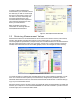
1.4 What’s New in InfraWin 5 The following is a list of improvements over the previous version of InfraWin. Device / Parameters: Detect available serial ports automatically with InfraWin. InfraWin can also search and list connected devices. Connect several pyrometers at the same time and maintain the ability to view and change the parameters for each connected pyrometer. View the device type (name), interface selection, and pyrometer parameters in one window.
1.5 Installing InfraWin To install the InfraWin Software Program: 1. Select setup.exe from the InfraWin Software CD or use the unpacked zip file downloaded from the internet. 2. On the Welcome Screen, click Next. 3. On the Ready to Install Screen, click Install. 4. On the Complete InfraWin 5 Setup Screen, click Finish.
To ensure consistent document formatting, this page was intentionally left blank.
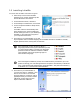
2 Getting Started 2.1 Starting the InfraWin Software If you chose to create a desktop icon during the installation process, you will be able to double-click the InfraWin 5 icon on your desktop to start the InfraWin software. If you did not choose to create a desktop icon during the installation process, you will be able to access the InfraWin 5 program through your Windows Start Menu.
In order to obtain simultaneous measurements, you will need to select the device(s) you wish to use through the Device/ Parameters menu. You can also load, view, and change the pyrometer parameters for each connected device as well as perform other functions pertaining to each device you have selected. Refer to Chapter 3 for more information on working with the Devices/Parameters Window. Figure 1: Devices/Parameters Window 2.
Note: When you close the Measurement window, recording stops and no additional values will be written to the STANDARD.I12 file until the Measurement window is once again opened. However, it is important to note that when the Measurement window is reopened, your old values will be overwritten by measurements obtained during the new session.
2.4.2 Saving Measurement Values to a New File To save measurement values to a new file: 1. Click the Exit with saving button located at the top of the Measurement window OR, If you have the Remind to Save feature activated, you can select Yes in the dialog box that appears when you attempt to close the Measurement window. A standard Windows™ dialog box will appear allowing you to save your file to your default InfraWin collections folder or to create a new folder in a directory of your choice.
3 Working with the Devices/ Parameters Window 3.1 Selecting Devices 1. Click the Devices/ Parameters button located on the Quick Access Toolbar. You can also access the Devices/ Parameters window by selecting Measurement > Devices/ Parameters from the Menu Bar located at the top of the page, or by selecting the Devices option found in the Measurement window, or by using the keyboard shortcut Ctrl+D.
Figure 6: Parameters Window Note: The free version of this software only allows you to select two measurement sources at the same time. This can be measurements from two devices or measurements from a single device and its internal temperature or intensity of signal (with 2 color pyrometer). Note: Once a device has been selected, you also have the ability to view and change the parameters of the device while in the Parameters Tab of the Measurement window.
3.2.1 Material Under Material you have the option of storing names of different measuring objects along with their emissivity values. Once this information is stored, you will be able to recall the item at any time from the list of choices. To add a material: 1. Click the Edit button next to the (mat.txt) drop-down list. 2. Enter the material in the form of “emissivity value”=”material”. Example: 95.0=Water 3.
If you are operating the device in ratio (two-color) mode, you will have the ability to add a value for the Emissivity Slope (K = 1 / 2). 3.2.5 EmiAutoFind If the true temperature of the measured object is known, you can calculate the emissivity of the measured object using the Emi: AutoFind function. When you click the Emi: AutoFind button, a measured temperature is displayed along with the current set emissivity. In the example below, the set emissivity is 57% and the measured Temperature is 239.4°C.
If the signal is too low for a correct measurement, the pyrometer interrupts the measurement and displays 1 °C below of beginning of the temperature range. Although the factory default is set to 10%, the switch-off limit can be adjusted between 2 and 50%, depending on the application. However, it is important to note that the smaller the value, the higher the chance that daylight or reflections will affect a correct measurement. 3.2.
Note: The maximum value storage coincides with adjustments made to the response time. Therefore: clear time the adjusted response time is useless clear times must be at least 3 times longer than the response time only maxima with full maximum value can be recorded, which appear at least 3 times longer than the response time. max / min When entering a reset time interval other than 0, it must also be determined with max or min if the maximum or minimum value storage will be activated.
of emitted signal (providing the object’s temperature) and unwanted reflected (and for transparent objects: transmitted) signals from objects (such as walls) in the environment. For example, under standard (lab) conditions, the walls have nearly the same temperature as the air, which is surrounding the pyrometer. In this case, the ambient compensation setting is set to “auto.” The pyrometer senses the environment as ambient air temperature and can compensate for this influence.
3.2.22 Limit switch (SP1) Some instrument types are equipped with a built-in Limit switch. The switching temperature and hysteresis of this switch can be set with InfraWin. For more information on this setting, refer to the documentation that came with your pyrometer. 3.3 3.3.1 Additional Settings Open/Save The open / save buttons enable you to save customized configurations, which can then be opened and reused at any time. 3.3.2 1 meas.
4 Measurement To learn more about obtaining and saving measurement values, view Sections 2.3 and 2.4. 4.1 Measurement Input/Output Screen The measurement function allows you to access a number of “input” tabs located on the left side of the screen. The main or home tab is the Output Screen. You can toggle the input tabs on and off by clicking them.
automatically by selecting the When signals exceed the border, the graphic scaling will be adjusted automatically option. This option will adjust the graphical scaling within the previously determined minimum and maximum values as they apply to the entire measurement. 4.1.3 Sampling Rate Tab In the PC sampling rate tab, a time interval can be set after individual measuring value is stored on the computer. If the time interval is longer, the saved file will be smaller.
4.2 Listing (analyzing) For analyzing the measured values in this field, all measured data appear in a numeric list. The date beside the time gives more exact values to see what happened on time units smaller than 1 s. The value specifies the time in seconds after midnight (0:00 h). The amount of data depends on the frequency that readings were taken (settings at PC sampling rates). As the amount of data increases, so does the amount of storage space required to save it. In order to save room, all .
Note: The last reading is saved in the standard.i12 file and automatically appears in this form upon opening Listing or Trend output. If file open was loaded using another file, the previous file will be overwritten and replaced by the standard.i12 file. 4.5 PC sampling rate (time interval between two measurements) This function sets a time interval. After each interval, one measured value is stored on the PC. Longer time intervals will result in creating smaller stored file sizes.
5 I/O Module The I/O Module allows accessories to connect to the software and is used to trigger measurements externally or to send a signal (like a relay) under certain conditions. 5.1 Searching for an I/O module There are four ways to start the search for an I/O module: 1. Use Instrument Search in Devices/Parameters. 2. Manually (before the search function starts) by clicking Options > I/O Module > Search I/O Module. 3.
To ensure consistent document formatting, this page was intentionally left blank.
6 Controller 6.1 About the programmable controllers The PI 6000 and PI 6000-N are programmable PID controllers that you can configure using InfraWin. 6.2 Operating the PI 6000 To operate the PI 6000, an IMPAC digital pyrometer is required as the transducer. When connected to the PI 6000, communication with the pyrometer is also via the controller. It can also be accessed directly (such as Devices/Parameters, Measurement). Baud rate and unit can only be changed by calling the programming window PI 6000.
To ensure consistent document formatting, this page was intentionally left blank.
7 Data format UPP® (Universal Pyrometer Protocol) Via interface and suitable communication software or via “Test” function of the InfraWin (see 3.3.5 Basic settings Test) commands can be exchanged directly with the pyrometer. The data exchange occurs in ASCII format with the following transmission parameters: The data format is: 8 data bits, 1 stop bit, even parity (8,1,e). The device responds to the entry of a command with: output (e.g.
Description Limit contact 1: Command AAs1XXXX Limit contact 2: AAs2XXXX Setting hysteresis of limit contacts: Changing °C / °F Interface type: Changing address: AAhlXX Changing baud rate: AAbrX *) Wait time: Error status: AAtwXX *) AAfs Lock keyboard: AAlkX Reading parameters: AApa Laser targeting light: AAlaX *) Internal temperature: AAgt Max. internal temperature: Ref.
Index A About This Manual 5 Address 18 Alarm Output Function 25 Ambient Temperature Compensation 18 Analog Output 18 B Basic Range 19 Baud Rate 18 C Channel Temp 19 Clear time of the maximum / minimum value storage 17 Connecting a Programmable Controller 9 Connecting a Pyrometer 9 Connecting Pyrometers 13 Connections Connecting to a PC 10 Controller 27 Conventions 5 Current Input 18 D Data format UPP® (Universal Pyrometer Protocol) 29 Device Settings Clear Peak Memory tclear 17 Dirty Window Warning 16 Sw
Address 18 Analog Output 18 Basic Range 19 Baud Rate 18 Laser 19 Sub Range 19 PC Interface Connecting to a PC 10 PC sampling rate 24 PI 6000 27 PI 6000-N 27 Programmable controllers 27 Z Zone 22 R Remind to Save Option 11 Response Time t90 17 S Sampling Rate 22 Saving Measurement Values 12 Scaling 21 Selecting Devices 13 Spot Size Calculator 24 Starting the InfraWin Software 9 System Requirements 5 T Temperature display in °C or °F 18 Threshold 22 Time interval 24 Transmittance 15 Trend output 23 Trigge