MANUAL IMPAC Pyrometer IS 12 IGA 12 IS 12-S IGA 12-S
Confidential Information The material contained herein consists of information that is the property of LumaSense Technologies and intended solely for use by the purchaser of the equipment described in this manual. All specifications are subject to change without notice. Changes are made periodically to the information in this publication, and these changes will be incorporated in new editions.
Contents 1 General Information...................................................................................................... 5 1.1 Information about the user manual..................................................................... 5 1.1.1 Legend ................................................................................................................. 5 1.1.2 Terminology ........................................................................................................ 5 1.2 Safety ..
5 Parameter descriptions / Settings............................................................................... 25 5.1 5.2 5.3 5.4 5.5 5.6 5.7 5.8 5.9 5.10 5.11 5.12 5.13 6 Emissivity .......................................................................................................... 25 Exposure Time (t90) .............................................................................................. 25 Clear time of the maximum / minimum value storage (tCL) ..............................
1 General Information 1.1 Information about the user manual Congratulations on choosing this high quality and highly efficient pyrometer. This manual provides important information about the instrument and can be used as a work of reference for installing, operating, and maintaining your pyrometer. It is important that you carefully read the information contained in this manual and follow all safety procedures before you install or operate the instrument.
Warning: To reduce the risk of injury to the eyes, do not look directly into the targeting laser and do not point the targeting laser into anyone's eyes. The instrument is equipped with a class II laser that emits radiation. Never look directly into the laser beam. The beam and spot can be watched safely from side. Make sure that the beam will not be reflected into eyes of people by mirrors or shiny surfaces. 1.2.
1.4 Unpacking the Instrument Before shipment, each instrument is assembled, calibrated, and tested at the LumaSense Factory. When unpacking and inspecting your system components, you need to do the following: 1. Check all materials in the container against the enclosed packing list. LumaSense Technologies cannot be responsible for shortages against the packing list unless a claim is immediately filed with the carrier. Final claim and negotiations with the carrier must be completed by the customer. 2.
Contact us to obtain an RMA number (if one has not already been assigned by Technical Support). Clearly indicate the assigned RMA number on the shipping package exterior. Send RMA Shipments to your nearest technical service center: Santa Clara, California Frankfurt, Germany LumaSense Technologies, Inc. 3301 Leonard Court Santa Clara, CA 95054 USA Telephone: +1 408 727 1600 +1 800 631 0176 LumaSense Technologies GmbH Kleyerstr.
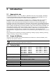
2 Introduction 2.1 Appropriate use The IMPAC pyrometers IS 12, IS 12-S, IGA 12, and IGA 12-S are very robust, digital, and highly accurate infrared thermometers with temperature ranges between 250 and 3500 °C for noncontact temperature measurement on metals, ceramics, graphite etc. For optimal match of the instrument to the application, six different fixed optics and three different focusable optics with extremely small spot sizes are available.
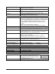
Digital interface: Display: Resolution: Isolation: Parameters: Emissivity : Exposure time t90: Maximum value storage: Limit switches: Accuracy*: ( = 1, t90 = 1 s, Tamb. = 23 °C) Repeatability: ( = 1, t90 = 1 s, Tamb. = 23 °C) Scanner adjustments: (only IS 12-S and IGA 12-S): switchable: RS232 or RS485 addressable (half duplex), baud rate 2.4 up to 115.2 kBd built-in 5 digit LED display, height 13 mm, additional function LED’s 0.1 °C at interface and display, < 0.
*Additional measurement uncertainty due to offset drift of the signal converter at long temperature ranges.
2.
2.6.2 Cooling The pyrometer can be used in ambient temperatures outside of the specifications if preventive maintenance is taken. The cooling plate is used to protect the pyrometer from heat coming from the front. The completely covered water cooling jacket made from stainless steel protects the pyrometer if exposed to a hot environment. It is designed for ambient temperatures up to 180 °C. 2.6.
To ensure consistent document formatting, this page was intentionally left blank.
3 Controls and Installation 3.1 Electrical Installation The pyrometers are powered by a voltage of either 24 V DC (15 to 40 V DC) or 24 V AC (12 to 30 V AC), 48 to 62 Hz. Once connected to power, the instrument operations immediately and needs no warm-up time. To switch off the instrument, unplug the connector. To meet the electromagnetic requirements, a shielded connecting cable must be used. The shield of the connecting cable has to be connected only on the pyrometer side to avoid ground loops.
Pin 7 5 1 3 6 4 2 8 Color pink white yellow grey green brown blue red Indication Limit contact S1 (drawing shows status without power or with exceeded limits) Limit contact S2 (drawing shows status without power or with exceeded limits) 2 5 3 4 1 8 7 6 Pin assignment of right connector (side of male inserts) The drawing of the limit contacts indicates their switch status without power. The limit contacts switch after supplying the pyrometer with power.
Connecting to RS485 interface Half-duplex mode: Terminator 120 Ohm Master A M D C L B A C K M L B1 DGND E F G M D H C J A A2 G B2 F B Pyrometer 1 e.g. address 00 A1 DGND E D H J B1 G A2 F B2 B1 DGND E A1 A2 B2 B S A1 A1 and A2 as well as B1 and B2 are bridged in the 12-pin round connector of the connecting cable, to prevent reflections due to long stubs. It also safeguards against the interruption of the RS485 Bus system should a connecting plug be pulled out.
center of the spot, not the exact size. The laser targeting light can be used without affecting the measurement. 3.3 Optics The pyrometers are equipped ex works with a fixed or a focusable optics. The smallest spot size for the fixed optics is shown for the specified measuring distance. With the focusable optics, the smallest possible spot size can always be adjusted for each distance within the optics limits.
Note: The pyrometer can measure objects at any distance but the object has to be bigger than or at least as big as the spot size of the pyrometer in the measuring distance. Calculating the spot sizes on different measuring distances: Spot sizes for other measuring distances can be calculated with the following equations or with the IR calculator of the InfraWin software. Table values: 3.3.
Adjusting the required measuring distance The required measuring distance must be adjusted to achieve the spot size mentioned in the tables above. This can be done between the smallest and the biggest limit value. Note: The measuring object has to be bigger than or at least as big as the spot size of the pyrometer. To release the optics, turn it counterclockwise. Then it can be pushed or pulled to find the correct measuring distance. To fix the optics, turn the optics clockwise.
4 Instrument Settings All instrument settings can be done directly at the instrument. Use the tip of a ball point pen to activate the adjusting keys. This avoids changing parameters by mistake. 4.1 Key panel operation Temperatureor parameter display Indication of limit switches Indication °C or °F Parameter indicator Emissivity Exposure time (t90/s) Clear time of max. value storage (tCL/s) Beginning of sub range (FROM) End of sub range (TO) Analog output 0 or 4 ...
3) ENT: If a parameter is changed with the arrow keys, the new value must be confirmed by pushing the ENT key. If it is not confirmed with ENT, the instrument will operate with the previous parameter value. If no key is pressed for approx. 30 s, the display changes to the temperature indication. Limit contacts: Two limit switches can be set. If the measuring temperature exceeds the adjusted limit contact temperature, the LED S1 or S2 displays the switch status.
4.4.1 Adjustments The scanning amplitude is adjustable with the scanning angle (0 to 4°) and when the scanning frequency is between 4 and 10 Hz. On the left side of the pyrometer is a cover. Two adjusting potentiometers are under this cover, labeled with an A for amplitude and an F for frequency. For adjustments, a small screw driver is necessary. With the laser targeting light, the adjustments can be controlled.
To ensure consistent document formatting, this page was intentionally left blank.
5 Parameter descriptions / Settings 5.1 Emissivity For a correct measurement, it is necessary to adjust the emissivity. The emissivity is the relationship between the emission of a real object and the emission of a blackbody radiation source (this is an object which absorbs all incoming rays and has an emissivity of 100%) at the same temperature.
5.3 Clear time of the maximum / minimum value storage (tCL) If the maximum value storage is always switched on, the highest last temperature value will be displayed and stored. The minimum value storage saves the lowest measurement taken during a reading. The storage has to be cleared at regular intervals and be replaced with a new and actual value. Settings: 0.00 s 0.01 s . ..
5.4 FROM / TO (beginning and end of sub range) You have the opportunity to choose a sub range (minimum 51 °C) within the basic measuring range of the pyrometer. This sub range corresponds to the analog output. “FROM“ describes the beginning of this measuring range, “TO“ the end of the range. With a sub range, it is possible to fulfill the requirements of the “auto” clear mode of the maximum value storage (see above). 5.
external indicator. If both displays show different readings the external indicator has a wrong temperature range or input current setting. The test function is switched off automatically after 1 minute and the instrument is working in the measuring mode. 5.12 Wait Time Using a pyrometer with RS485 it is possible that the connection is not fast enough to receive the pyrometer’s answer to an instruction of the master. In this case, a wait time can be set to slow down the data transfer (e.g.
6 Software InfraWin The operating and analyzing InfraWin software is included with delivery of the pyrometer. In addition to allowing you to make parameter adjustments via PC, the InfraWin software also provides temperature indication, data logging, and measurement analysis features. A software description can be found in the program’s help menu. Click on the F1 button after loading InfraWin or click on the ? in the menu bar. The latest version is available for free as download from the homepage www.
To ensure consistent document formatting, this page was intentionally left blank.
7 Maintenance 7.1 Cleaning the front window Since the device does not contain parts that require regular maintenance, the only regular maintenance required is periodic inspection of the front window for build-up of foreign particiles. If allowed to build up, the particles can influence the energy received by the instrument. The window is not water soluable and can be cleaned with standard lens tissue dampened with a commercially available glasses or camera lens cleaning solution.
7.2.2 Focusable optics replacement Only the lens will be replaced for changing the focusable optics. The fixing ring has to be removed with a suitable objective wrench. After removing the old lens, put in the new one with the convex side to the front. Fix the lens with a new O-ring and the new fixing ring. On the inside of this ring is the sticker with the optics data.
8 Troubleshooting Before sending the pyrometer for repair, try to find the error and to solve the problem with the help of the following list. Temperature indication too low Incorrect alignment of the pyrometer to the object New correct alignment to achieve the max.
To ensure consistent document formatting, this page was intentionally left blank.
9 Data format UPP (Universal Pyrometer Protocol) Via interface and suitable communication software or via Test function of the InfraWin software commands can be exchanged directly with the pyrometer. The data exchange occurs in ASCII format with the following transmission parameters: The data format is: 8 data bits, 1 stop bit, even parity (8,1,e). The device responds to the entry of a command with: output (e.g. the measuring value) + CR (Carriage Return, ASCII 13), to pure entry commands with ok + CR.
Description Analog output: Limit contact 1: Command AAasX AAs1XXXX Limit contact 2: AAs2XXXX Setting hysteresis limit contacts: Changing °C / °F Interface type: Address: AAhlXX Baud rate: AAbrX Wait time: Error status: AAtwXX AAfs Lock keyboard: AAlkX Reading parameters: AApa Laser targeting light: Internal temperature: Max. internal temp.: Ref.
10 Reference Numbers 10.
3 821 200 3 852 290 3 852 540 3 852 550 3 890 640 3 890 650 3 890 560 3 826 510 3 890 630 3 826 720 3 852 580 3 852 600 3 835 060 3 837 200 3 837 210 3 834 330 3 834 140 3 843 260 Additional cable for limit contacts, 5 m, temperature resistant up to 200 °C Power supply NG DC for DIN rail mounting; 100 to 240 V AC 24 V DC, 1 A Power supply NG 0D; DIN rail mount, 85...
Index A Accessories 12 Address 27 Air purge 13 Ambient temperature 6 Analog Output 27 Analyzing devices 17 Appropriate use 9 B G General Information 5 I Installation 29 Electrical 15 Instrument Settings 21 Interface 16 Baud Rate 27 Built-in Scanner 22 K C L Changing of optics 31 Cleaning the front window 31 Clear time 26 Clear time of the maximum / minimum value storage 26 Connecting the pyrometer to a PC 29 Connector assignment 15 Controls and Installation 15 Cooling 13 Language 29 Laser targeting
Instrument 37 Reference Numbers 37 Repair 7 RS232 16 RS485 17 S Safety 5 Scale °C or °F 22 Scope of delivery 9 Service Request 7 Setting keys 21 Settings / parameter descriptions 25 Shield 15 Sighting 17 Software InfraWin 29 Spot size 19 Storage 8 Sub range 27 Support 7 Switch Contact 28 T Targeting light 21 Technical Data 9 Temperature Display 21 Temperature display in °C or °F 27 Test Current Output 27 Thru-lens view finder 17 Transport 8 Troubleshooting 33 U Unpacking the Instrument 7 UPP data format